Creating a Pendulum Monitor with the Wolfram Language and the SparkFun Blocks for Intel Edison
Guest blog post by Arnoud Buzing of Wolfram Research on using the Edison and SparkFun Blocks to make a pendulum monitor.

Arnoud Buzing has worked on various initiatives to bring the Wolfram Language to embedded devices. He led the project to make the Wolfram Language available free on the Raspberry Pi and is working on making a version available for Intel Edison as well. In the post, Arnoud describes how he loaded the Wolfram Language onto the Edison and used several SparkFun Blocks to make a sensor that monitors the movement of a pendulum.
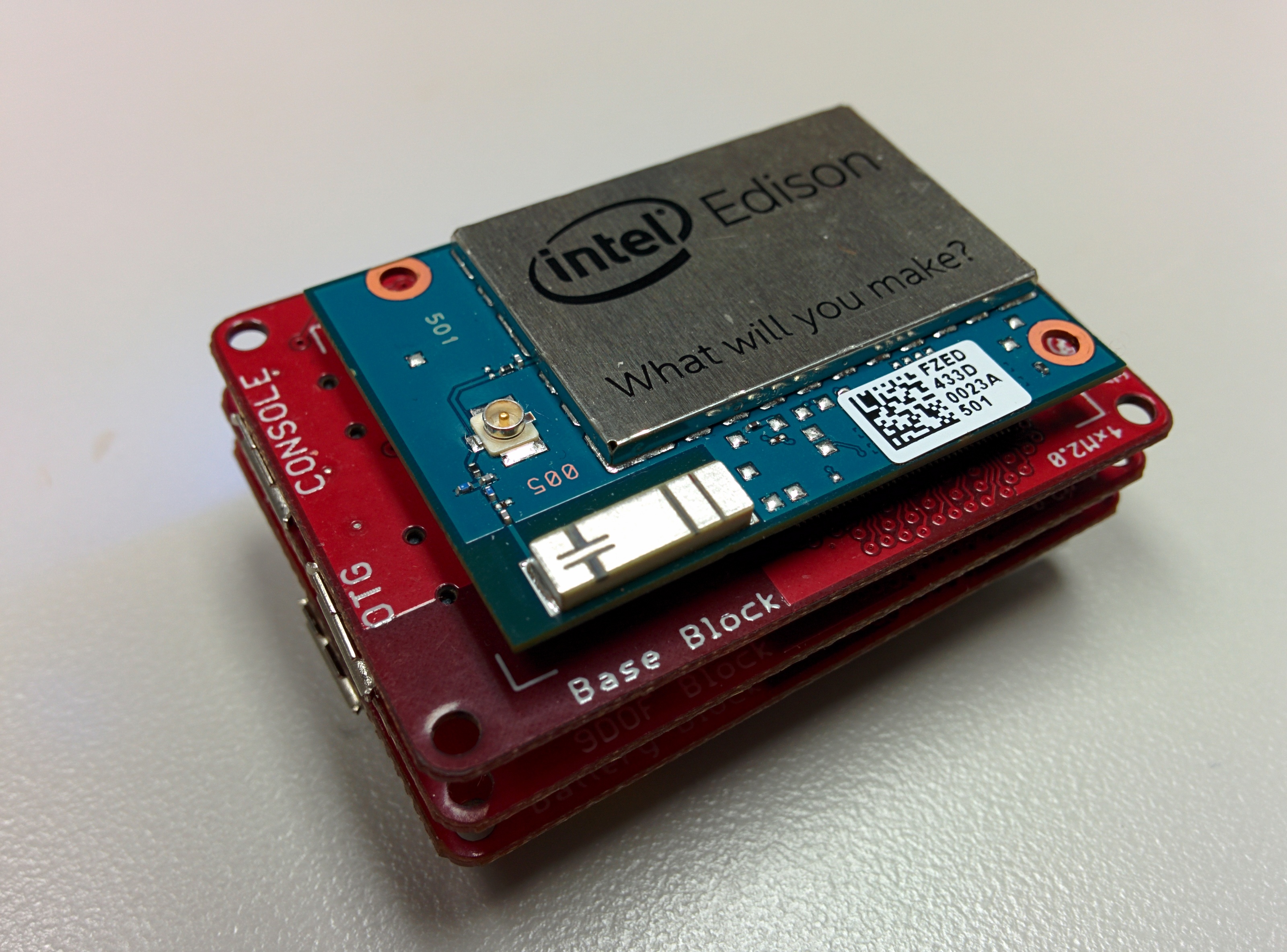
Just recently, SparkFun released the Blocks for the Intel Edison, which include a dozen or so little electronic building blocks that you can plug into the Edison using a Hirose connector. The cool thing about this is that these blocks are completely stackable, so you can mix and match any component you like.
I was kindly given an early starter pack to try these out with the Wolfram Language for the Intel Edison (which we hopefully will release soon for the general public). If you are not familiar with the Wolfram Language, you should take a peek at this fast introduction, which explains the main ideas behind this programming language and includes a basic introduction to get you started.
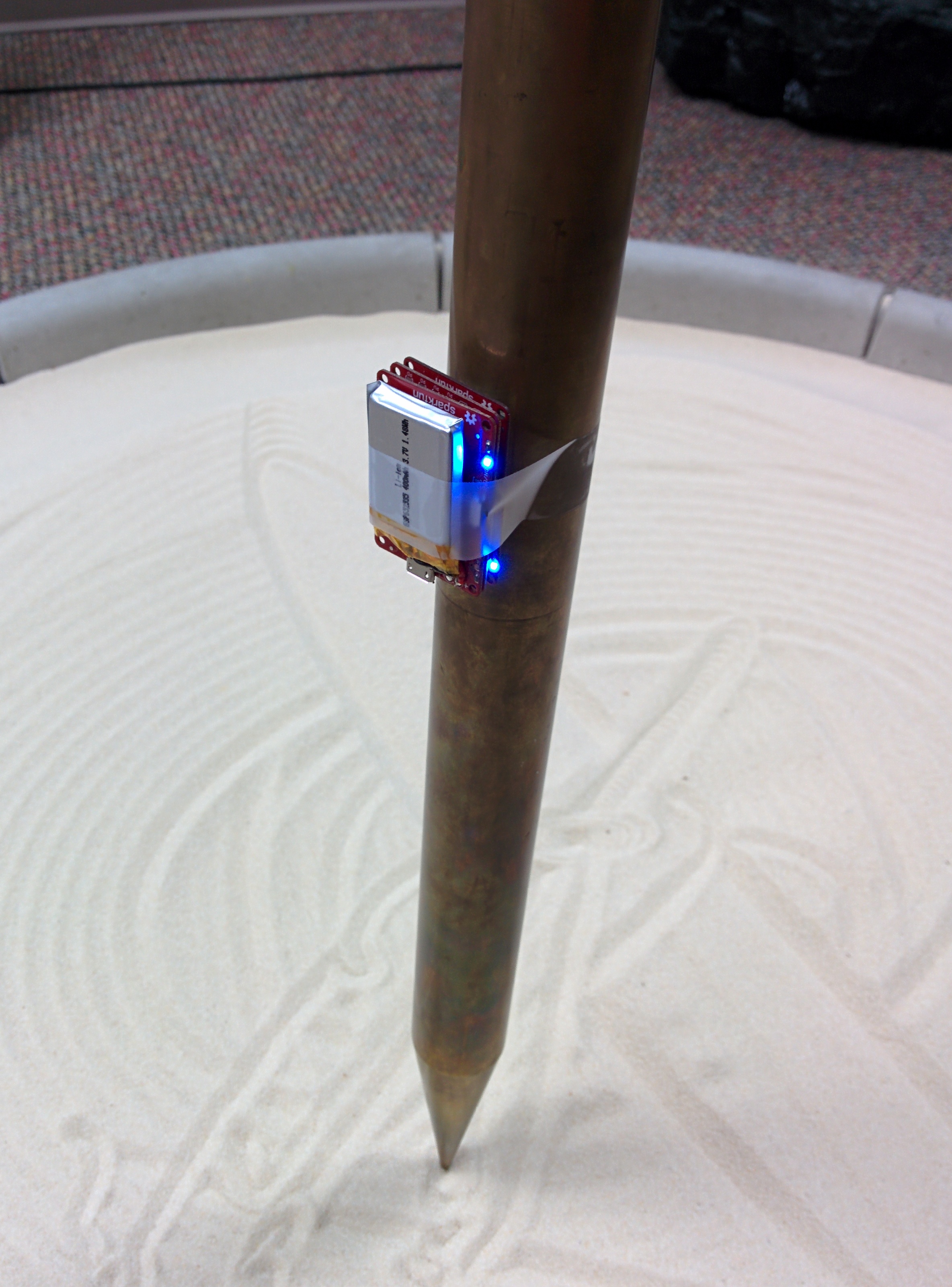
For this experiment, I used the 9DOF (degrees of freedom) Sensor Block, which measures linear acceleration (x, y, z), magnetic field strength, and angular rates. Additionally, I used the Battery Block to power the Intel Edison, and the Base Block to have a wired communication option to the Edison. The end goal of this experiment was to have this whole contraption measure linear acceleration continuously and communicate this data over WiFi to a personal computer for visualizing the results in real-time.
Here is a video of the result:
Watching pendulum acceleration forces on your computer from Arnoud Buzing on Vimeo.
The actual sensor on the '9DOF Block' is a LSM9DS0 sensor. There are two ways to communicate with this sensor: I2C and SPI. The Wolfram Language does not (yet) come with built-in support for either, so I wrote a simple I2C interface to be able to communicate with the device. For this, I used a software component of the Wolfram Language called LibraryLink.This lets you easily connect a piece of C code and compile it into a library that can be loaded by the Wolfram Language. To see some simple examples of how to use LibraryLink, please visit this post on the Wolfram Community.
The C code for the I2C interface is included below (DOF.c). The code will open the I2C device, select it (at its address 0x6b) and make sure the sensor is turned on. After that it reads 2 bytes for the x acceleration value, 2 bytes for the y acceleration value and 2 bytes for the z acceleration value. These bytes are then returned to the Wolfram Language, which takes care of all the high level processing from that point on.
The Wolfram Language code that runs on the Intel Edison side (DOF.m) loads the .c file, compiles it, and creates a dynamic library for it, which then gets loaded into the language:
Needs["CCompilerDriver`"];
lib = CreateLibrary[{"DOF.c"}, "DOF"];
DOF = LibraryFunctionLoad[lib,"DOF",{},{Integer,1}];
At this point DOF[] is a function that takes no arguments and returns a list of (six) bytes, which are the raw sensor readings:
In[]:= DOF[]
Out[]= {81, 255, 25, 0, 50, 254}
We then need to convert those six bytes into 'normal numbers' taking care of their specific format (two's complement):
convert[{hi_,low_}] := BinaryRead[StringToStream[FromCharacterCode[{hi,low}]],"Integer16",ByteOrdering->1];
And convert the six bytes, two at a time, to integers:
dof[] := Module[{d=DOF[]},{
  convert[{d[[2]],d[[1]]}],
  convert[{d[[4]],d[[3]]}],
  convert[{d[[6]],d[[5]]}]}
 ]
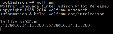
To set up communication from the Edison to a personal computer, we use the Wolfram Symbolic Transfer Protocol (a mouthful, so "WSTP" from now on). We select the WiFi machine address (for me 10.14.something) and create a link:
host = First @ Select[ $MachineAddresses, StringMatchQ[#,"10.14.*"] & ];
link = LinkCreate[ LinkProtocol -> "TCPIP", LinkHost -> host ];
Then we use the Wolfram Programming Cloud to communicate the link address to the personal computer. We will use that later to facilitate the connection on the other end:
co=CloudObject["edison"];
CloudPut[First[link],co]; (* store the link information in the cloud *)
Print[ First[ link ] ];
Finally we tell the Wolfram Language on the Intel Edison to let the personal computer take control of the link from now on:
$ParentLink = link;
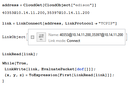
Now we need to switch to the personal computer side of things. We launch Mathematica to get the notebook interface to the Wolfram Language. The first thing we need is the link information for the link we just created on the Intel Edison:
address = CloudGet[CloudObject["edison"]]
And then we can connect to it:
link = LinkConnect[address, LinkProtocol -> "TCPIP"]
We can check that the link is now ready for communicating:
LinkReadyQ[link]
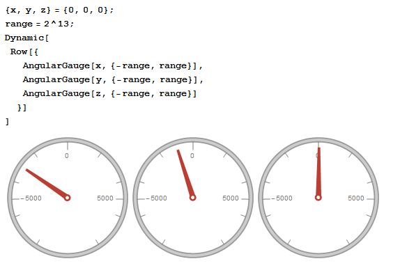
The next step is to set up the visualization code, which consists of three angular gauges. The displayed range can go all the way up to +/-2^15, but for the pendulum experiment a much smaller value of 2^13 is better to visualize the accelerations:
{x, y, z} = {0, 0, 0};
range = 2^13;
Dynamic[
 Row[{
   AngularGauge[x, {-range, range}],
   AngularGauge[y, {-range, range}],
   AngularGauge[z, {-range, range}]
   }]
 ]
Here, the Dynamic function takes care of updating any visual element whenever x, y, or z changes.
Now we can execute the loop, which communicates with the Intel Edison and updates the values for x, y, and z:
While[True,
  LinkWrite[link, EvaluatePacket[dof[]]];
  res = LinkRead[link];
  {x, y, z} = ToExpression[res[[1]]];
 ]
This loop will cause the angular gauges to update whenever the sensor readings change.
The end result can be seen in the video above. I hope you enjoy it!
DOF.c
language:c
#include "WolframLibrary.h"
#include <stdio.h>
#include <stdlib.h>
#include <sys/stat.h>
#include <fcntl.h>
#include <sys/ioctl.h>
#include <linux/i2c-dev.h>

#define UNABLE_TO_OPEN_I2C 128;
#define UNABLE_TO_SELECT_DEVICE 129;
#define UNABLE_TO_TURN_ON_SENSOR 130;

DLLEXPORT int DOF( WolframLibraryData libData, mint Argc, MArgument *Args, MArgument Res) {

/* open the i2c device */

        int file;
        file = open( "/dev/i2c-1", O_RDWR );
        if( file < 0 ) { return UNABLE_TO_OPEN_I2C; }

/* select the device */

        int addr = 0x6b;
        int iores;
        iores = ioctl( file, I2C_SLAVE, addr);
        if( iores < 0 ) { return UNABLE_TO_SELECT_DEVICE; }

/* make sure the sensor is on */

        unsigned char on_command[2] = { 0x20, 0x0f };
        if( write(file, on_command, 2) != 2 ) { return UNABLE_TO_TURN_ON_SENSOR; }

/* declare variables for reading and writing */

        unsigned char buffer[1];
        int result;

/* set the register */

        buffer[0]= 0x28;
        if( write(file, buffer, 1) != 1 ) { return LIBRARY_FUNCTION_ERROR; }

/* read from the register */

        result = read(file, buffer, 1);
        if( result != 1 ) { return LIBRARY_FUNCTION_ERROR; }
        int OUT_X_L_G = buffer[0];

/* set the register */

        buffer[0]= 0x29;
        if( write(file, buffer, 1) != 1 ) { return LIBRARY_FUNCTION_ERROR; }

/* read from the register */

        result = read(file, buffer, 1);
        if( result != 1 ) { return LIBRARY_FUNCTION_ERROR; }
        int OUT_X_H_G = buffer[0];

/* set the register */

        buffer[0]= 0x2a;
        if( write(file, buffer, 1) != 1 ) { return LIBRARY_FUNCTION_ERROR; }

/* read from the register */

        result = read(file, buffer, 1);
        if( result != 1 ) { return LIBRARY_FUNCTION_ERROR; }
        int OUT_Y_L_G = buffer[0];

/* set the register */

        buffer[0]= 0x2b;
        if( write(file, buffer, 1) != 1 ) { return LIBRARY_FUNCTION_ERROR; }

/* read from the register */

        result = read(file, buffer, 1);
        if( result != 1 ) { return LIBRARY_FUNCTION_ERROR; }
        int OUT_Y_H_G = buffer[0];

/* set the register */

        buffer[0]= 0x2c;
        if( write(file, buffer, 1) != 1 ) { return LIBRARY_FUNCTION_ERROR; }

/* read from the register */

        result = read(file, buffer, 1);
        if( result != 1 ) { return LIBRARY_FUNCTION_ERROR; }
        int OUT_Z_L_G = buffer[0];

/* set the register */

        buffer[0]= 0x2d;
        if( write(file, buffer, 1) != 1 ) { return LIBRARY_FUNCTION_ERROR; }

/* read from the register */

        result = read(file, buffer, 1);
        if( result != 1 ) { return LIBRARY_FUNCTION_ERROR; }
        int OUT_Z_H_G = buffer[0];

/* return the results */

        MTensor out;
        mint out_type = MType_Integer;
        mint out_rank = 1;
        mint out_dims[1];
        mint* out_data;
        int err;
        out_dims[0] = 6;
        err = libData->MTensor_new( out_type, out_rank, out_dims, &out );
        out_data = libData->MTensor_getIntegerData(out);
        out_data[0] = OUT_X_L_G;
        out_data[1] = OUT_X_H_G;
        out_data[2] = OUT_Y_L_G;
        out_data[3] = OUT_Y_H_G;
        out_data[4] = OUT_Z_L_G;
        out_data[5] = OUT_Z_H_G;
        MArgument_setMTensor(Res, out);

/* close the file */

        close(file);

        return LIBRARY_NO_ERROR;
}
DOF.m
Needs["CCompilerDriver`"];
lib = CreateLibrary[{"DOF.c"}, "DOF"];
DOF = LibraryFunctionLoad[lib,"DOF",{},{Integer,1}];

convert[{hi_,low_}] := BinaryRead[StringToStream[FromCharacterCode[{hi,low}]],"Integer16",ByteOrdering->1];

dof[] := Module[{d=DOF[]},
 {convert[{d[[2]],d[[1]]}], convert[{d[[4]],d[[3]]}], convert[{d[[6]],d[[5]]}]}
]

host = First @ Select[ $MachineAddresses, StringMatchQ[#,"10.14.*"] & ];
link = LinkCreate[ LinkProtocol -> "TCPIP", LinkHost -> host ];


co=CloudObject["edison"];
CloudPut[First[link],co];
Print[ First[ link ] ];

$ParentLink = link;


IslandFox,
The angular gauges are actually showing angular acceleration, not linear acceleration. I am working on a version which addresses this (it should be using linear acceleration to make more sense). In either case case, doubly integrating acceleration data (to get position) seems to be something you should avoid doing (i.e.: http://physics.stackexchange.com/questions/36312/calculation-of-distance-from-measured-acceleration-vs-time).
I am seeing that the first angular gauge (the 'x'), always has a slight negative reading (tilted left). The first angular gauge probably denotes up/down movement from the ground. Given that the pendulum almost doesn't leave the ground and stays on the sand surface, it is understandable that we get zero-ish readings for that axis. But why is it always negative? Shouldn't it fluctuate between + and - since the pencil probably rises up from the ground very little and then comes back and so on?
I guess I am just wondering how reliable is the LSM9D sensor in general? I was hoping to use this chip for some positional tracking by double integrating the acceleration data. But if there is too much noise maybe this is not the right sensor.
Not familiar at all with Wolfram language, but in general, the ability to compile C code on-the-fly and then load it as a dynamic library seems cool.