
Introduction
Power supplies are everywhere these days. With the advent of switching power supplies, the cost of high-current supplies has radically dropped. Maybe you've noticed how the large, heavy, wall-wart style adapters are no longer lurking around your baseboards, falling out of their sockets? Or occupying several of your valuable power-strip positions? But not all power supplies are created equal.
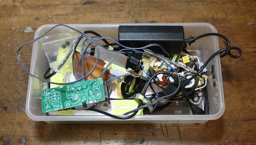
A selection from the power supply box of shame.
Whenever I get disgusted by a power supply, I inevitably tear it apart, judge it, and throw it at my power supply box of shame. There are so many of these light-weight supplies out there today that my collection is constantly growing and evolving based on what I deem to be a good supply.
This article takes a cursory look at what's typically inside, and what quantities are measured during validation of a supply.
Engineering Triangle
Before I get into the meat of it, consider this diagram commonly presented as engineering curriculum.

An engineering/project management triangle. Pick 2 of 3!
This diagram is used when looking at products from a very high level. A customer may ask for a product that has tons of features, is super cheap, and was available yesterday. At this, the engineer scoffs and says "pick two." It can be made quickly and with high quality, but it will cost a lot. Or, if you find it fast and cheap, perhaps the quality is suffering.
The triangle is applicable to power supplies because they take a great deal of work to make well, yet customers are crying for cheap supplies. As a supplier of electronics, it's a constant struggle and compromise.
Certification Marks
Take a look at the nearest power supply labeling. It will hopefully have a slew of marks on it that indicate what standards it abides to. Politically, each country is a little different and thus has different ideas of which standards are relevant, so naturally a product with a worldwide customer base is going to have many of these marks (check out your laptop's power brick).
Or, if the product is destined for America, it might only have a UL mark.
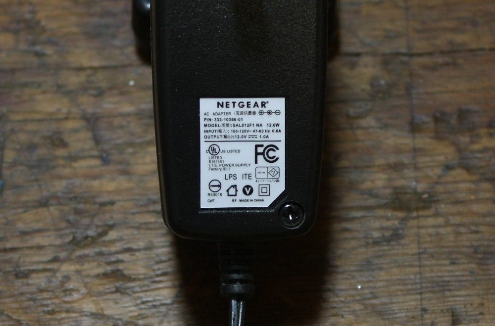
Here's a supply for some Netgear product. I recognize the FCC mark (F with nested Cs), Underwriters Laboratories (circled UL), and double insulation (nested squares) mark.
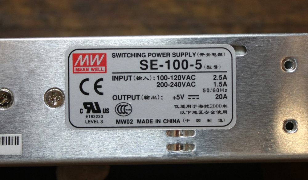
This is the label on a MeanWell supply we're currently vetting. They establish adherence to the Conformité Européenne (CE), RU (which is Registered component with UL for America and Canada), and this strange CCC mark I looked up and seems to be UL for China.
I found a website that lists various marks with picures. I have to ask myself, "What's to stop people from just printing the logo on the label?" There's a huge fine involved if the agency catches you, but if the product is coming from some unknown supplier it can be dicey. One common thing to do is to print the "CE" logo with the 'C' and 'E' spaced closer together, which is known as a China Export and doesn't have anything to do with what we call CE.
What's in a Supply?
Without describing the math behind how to select component values, here's a basic example circuit of what's inside an AC-DC switching supply.
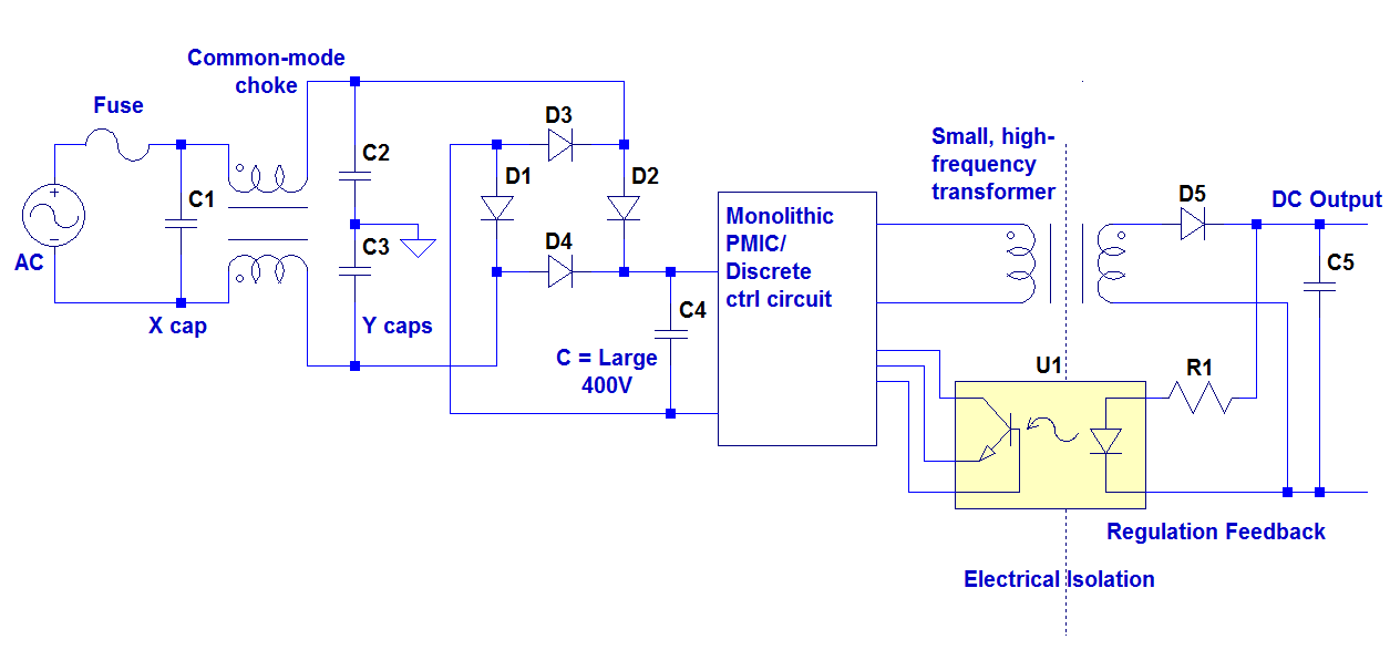
AC power from the line is rectified and stored in a large capacitor rated above peak line levels. From this DC source, high frequency (>20kHz) switching is generated to drive the primary of a transformer. The stepped down voltage is rectified and passed back through an opto-isolator to provide regulation information to the switching controller.
Parts of the circuit:
- Fuse -- Prevents fires
- X and Y caps -- Named by their shape in the circuit, these provide high frequency shunting to chassis for noise control.
- Common mode choke -- Cancels common-mode noise on the input wires
- Diode bridge -- Steers the AC into DC
- Primary-side cap -- Smooths rectified AC into useable DC at a high voltage
- PMIC -- Power management integrated circuit, or collection of discrete components that act to switch the transformer's primary side
- Transformer -- Provides isolation and ratiometric scaling of power down to the desired voltage
- Secondary side Diode -- Rectifies back to DC
- Feedback coupling -- Provides information about output voltage for the PMIC's decision making process
Also, sometimes I refer to the primary side components as the "high side" and secondary as "low side."
Tear-downs
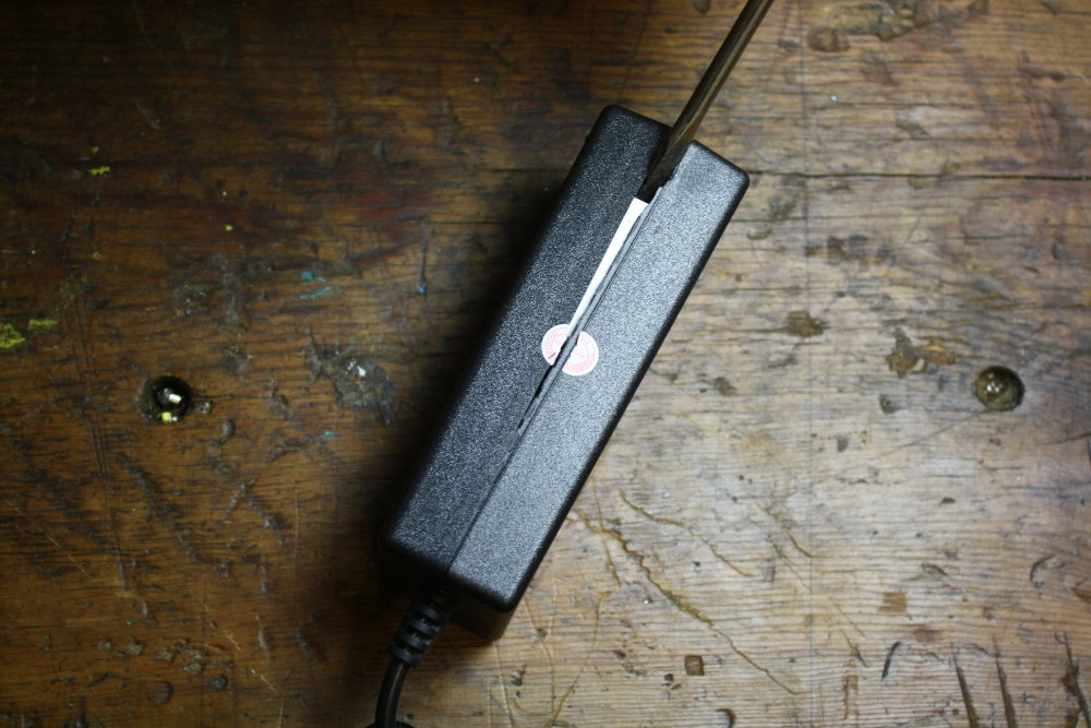
Molex-pinned Supply
This is our 12V/5V Power Supply. Judging from the comments, customers absolutely love this supply. Oh wait, I think I read that wrong. This supply is just $9.95. Looking at the engineering triangle, something else has to give.
Let's have a look!

This first picture shows the label. The nested squares indicate double insulation and thus no chassis ground required. The enclosure is all plastic. Oh no, that 'C' and 'E' are too close together!
A quick palm-hit to the screwdriver cracks the glue line. We're in!
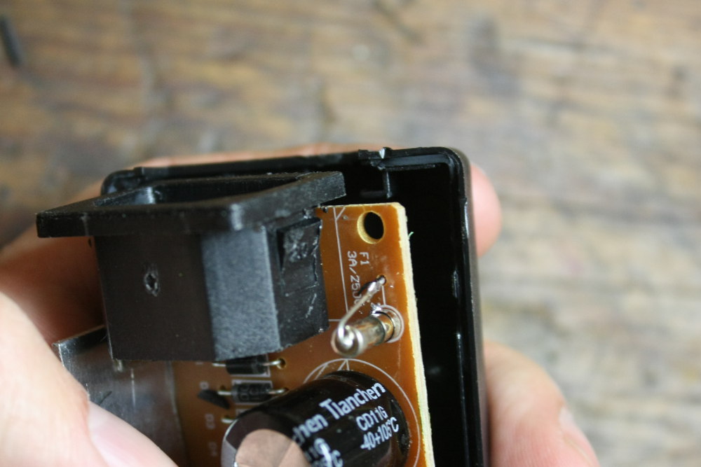
Notice the 'L' shaped retention of the IEC socket. It prevents force from pushing the socket inward when installing the line cord, and is a good idea.
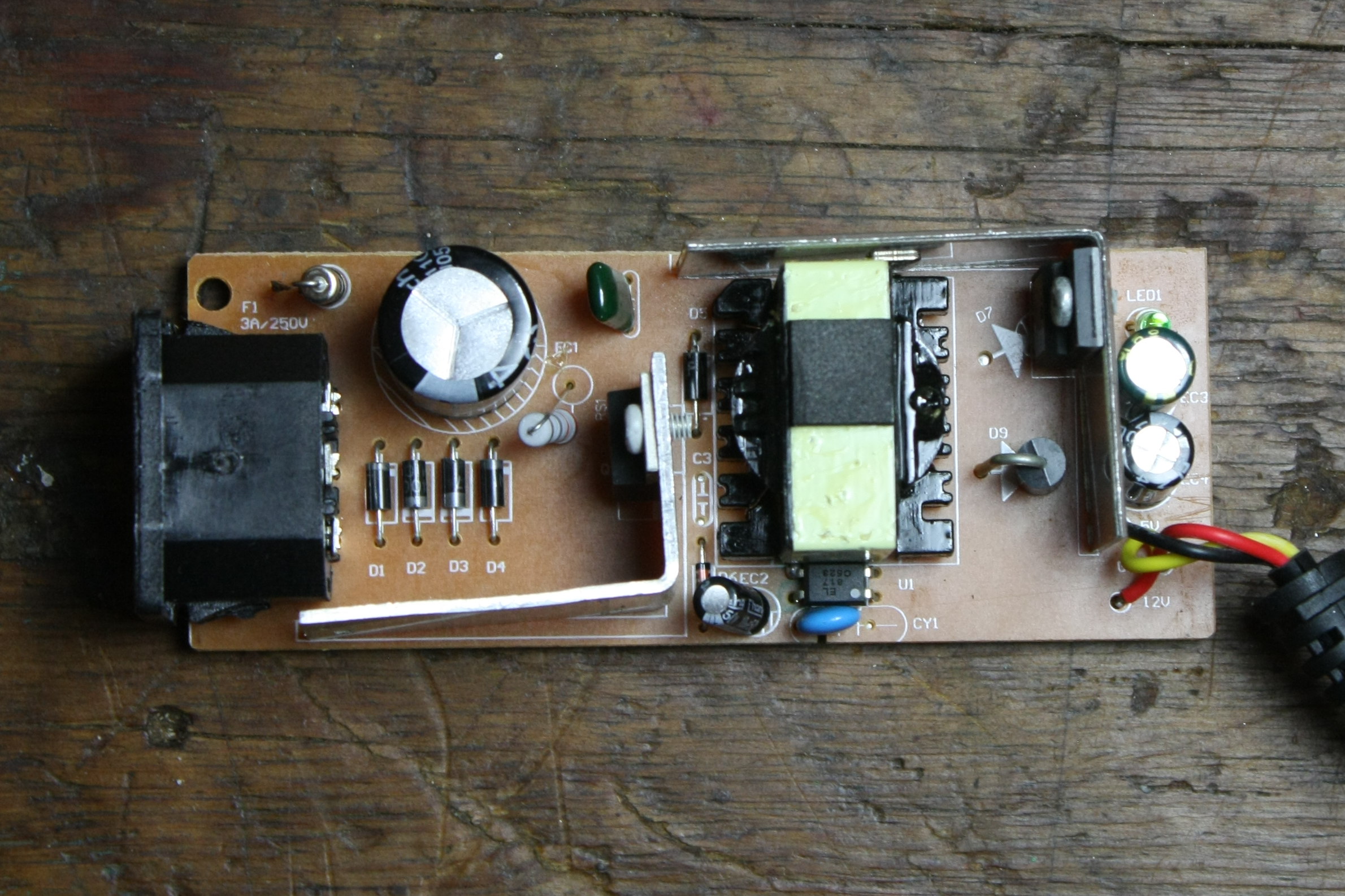
There's really not much in this power supply. No line filtering is present but we do have a fuse. The large cap to the left is rated 400V so this supply should be good world-wide, as indicated by 100-250VAC input rating on the label. On the right you can see a couple diodes (one is TO-220 packed), with two output caps, one for each voltage. These output caps are only rated 10 and 16 V, which is in the spec but isn't the best. I've seen broken supplies with wild outputs and blown caps, so I'm not surprised. Specifying high quality caps with solid margin contributes directly to price.
Here we can see how the output of the transformer is wired. It has three secondary terminals, one of which is connected to something like a ground plane, common to all electrolytic caps and the output. Assuming this is a tap point of the windings, the other two terminals are coils to the 12V and 5V rails. Each has a single diode so that during the positive and negative phases, the transmitted flux works on alternate output rails to balance the load.
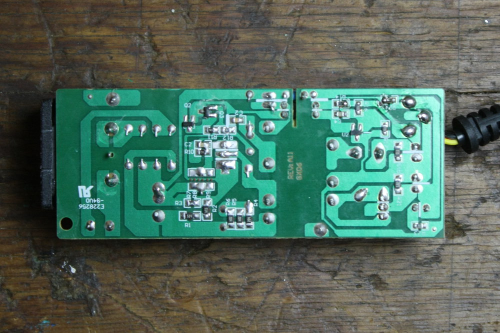
Notice the slot underneath the optocoupler. This will come up again later. It's to prevent creepage of electrons along the surface of the soldermask from reducing the high-voltage standoff of the isolation region, which can be seen as the area under the transformer that is free of copper. Also straddling this slot is a cap designed to provide a path for high-frequency noise back to the neutral wire of the supply.
I noticed that the primary side of the transformer actually has two windings, then noticed that there are some diodes and a couple transistors associated with the extra winding. These form an oscillator that drives the 4N60 power NMOS, which is hanging out by the primary-side bulk cap.
All in all, this supply is fairly clean but doesn't have any features. We'll put it in the "Fast and Cheap" side of the engineering triangle. It doesn't have regulators on the secondary side, so loading down one of the output rails probably causes the other one to do some funny things. I wouldn't use this on a valuable hard drive but could re-regulate the output, or supply tolerant loads with it.
Google USB Adapter
I saw this cute little Google branded USB output adapter at the thrift store and couldn't resist buying it to take apart. I'll probably tape it back together and get some use out of it afterward.
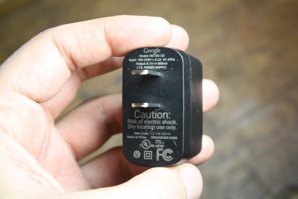
What was this adapter intended for?

A good technique to get inside these types of heavily-molded, gluded pods is to saw most of the way through the thickness on one side, then torque apart the halves with a flathead screwdriver.
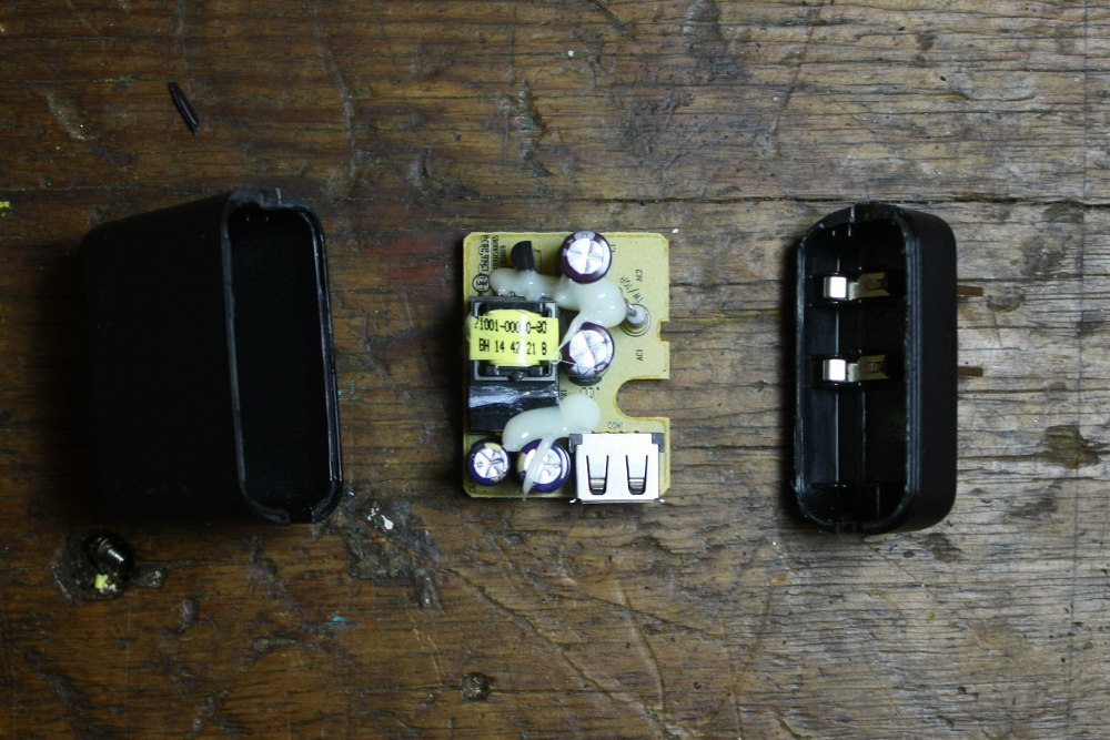
Wow! The plug spades are spring contacts against the board edge! I haven't seen this before.
From the top side we can only see a few things:
On the high side, there are two caps (400V rated), a 3N4 marked TO-92 (probably a high-voltage mosfet) and a couple resistors. No fuse, so hopefully the 10ohm marked resistor in-line with the line terminal acts as a PTC (positive temperature coefficient) device to protect us from fires.
On the low side, there's nothing but a couple of caps and a USB port visible. No feedback network.
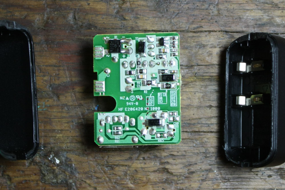
Following the flow of power, the line first encounters a bridge rectifier and then fills the two storage caps. This view reveals a similar circuit to the molex output supply, in that it has extra windings and a diode for some high-side biasing circuitry/measurement coil. Rather than two discrete transistors for an oscillator, this carries a SOT23-5 IC, which is probably a PMIC of some kind. Notice that on the low side, there's an additional diode and two resistors – that's it. There's no feedback path so regulation must occur in another way: primary side regulation.
Primary side regulation is the act of regulating the output of the secondary winding by only measuring and manipulating the high voltage side of the transformer.
I actually wanted to see what the output looked like but the supply did not come on! OK Google...
Li Shin International Laptop-Type Supply
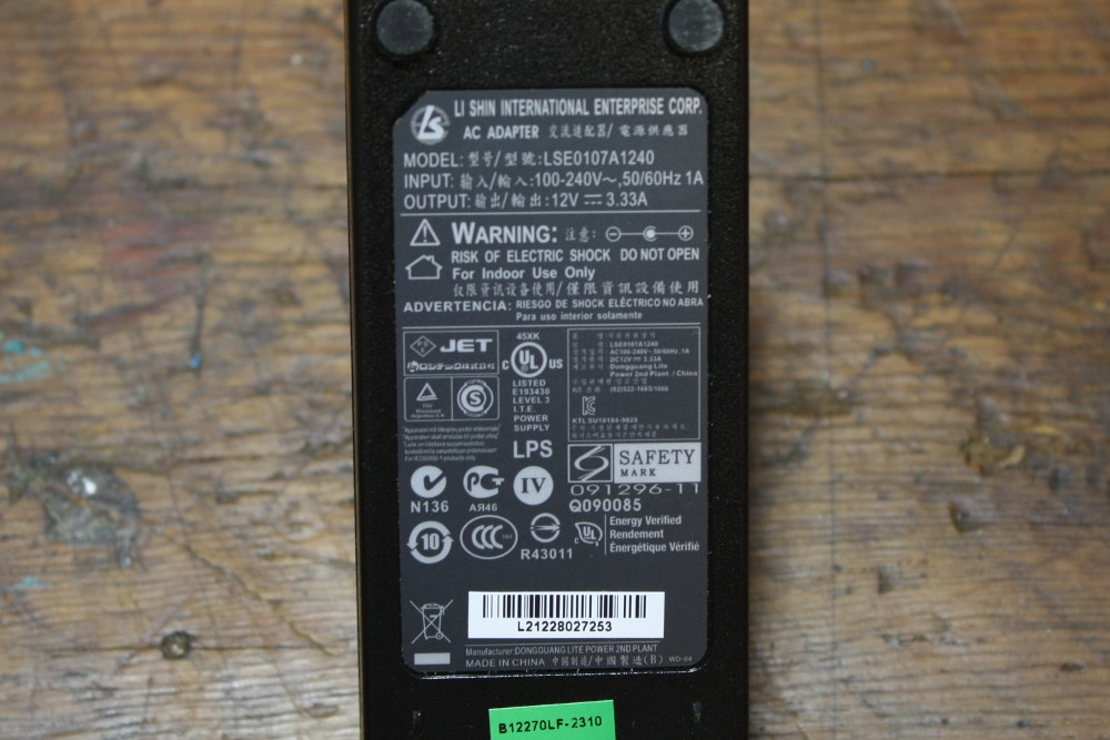
I grabbed this one from the thrift shop because it boasts 3.3 A at 12 V and I thought it would be useful. But then I took it apart because that's what I do with all my favorite toys.
I've had a few of these Li Shin International supplies in my life and I've never had a problem with them. Typically, they're used for laptop supplies but work great for anything at the right voltage. It used screws for the case, and I even noticed that the case is shot with UL listed plastic, which is a good sign.

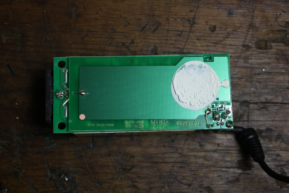
The first thing that struck me was the size of that high-side cap in this supply. It's so big they used it as a place to put their manufacturing-process label, a common problem when board space is at a premium. The next thing I noticed is the big blue box with the e1 sticker. This is the X cap. Down at the surface level you can see a green, pea shaped cap (later I determined this to be a fuse-like protection device), which is a Y cap, plus some empty sections where other caps could be placed -- provisional Y caps. This tells me the corporation at least has people working who have done line noise tests before and gave it a shot. As a best case, they performed and passed their emission testing without needing to populate the additional components.
Speaking to quality, this has two 16V 1000 uF caps on the low voltage side, and is a 3.3A 12V supply. Our Molex output supply had a single 16V 1000 uF cap for a 2A 12V supply, yet the cap volume was about half. By volume, this supply has four times the cap for less than two times the current. I suspect these caps have more insulation and electrolyte, and will last much longer.
On the back side, there's an extra PCB used as a shield plane. Good news! They wouldn't pay for this without reason. They may have run a radiated emissions test, failed, and found that this shield was the solution. This product shows evidence of actually being able to comply with EMC standards.
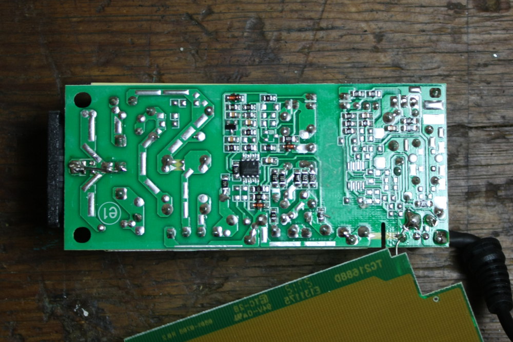
Under the PCB the design becomes more clear.
The left third:
- The two outer pins of the IEC plug route to the various Y cap positions, which couple back to chassis ground.
- The green pea is the upper leftmost component, and can be seen to interrupt the circuit in series so it must not be a Y cap, but actually a fuse-like protection device of some kind.
- The four pins in a square are the common-mode choke.
- You can find the X cap across two of the terminals of the common-mode.
- After the common-mode choke, the four inline pins are the bridge rectifier.
- Next comes the high-voltage cap.
The middle:
- Right off the high-voltage cap there's a mosfet along the lower edge.
- There's a high impedance tap for the SOIC-8 IC, the PMIC for the supply -- to get it charged and switching before the self-supply is operational.
- Near the top, the wide spaced four pins of an opto-isolator can be seen, spanning the isolation region.
- The transformer has four high-side terminals. Two of the terminals are associated with the switching mosfet, while the other two have a cap and single diode -- a supply for the PMIC once it's started.
The right third:
- The output two pins of the transformer are near the middle of the mess.
- An unpopulated SOIC-8 footprint exists, probably for a second output voltage option.
- A TO-220 near the top edge rectifies the output AC to DC.
- Output caps are along the right edge.
- The drive side of the opto can be seen at the top, with some biasing resistors.
- The shield PCB is connected at the DC ground connection.
The shield PCB connects the output DC ground all the way back to chassis ground. For this supply, probably intended for a laptop, this means that static charge - and other faults to the laptop case - should safely be routed back to the grounding system of the building it's being used in. As the output side of the transformer is isolated from the input side, the chassis is still isolated from the mains.
MeanWell
Here's a supply we're currently vetting. The sticker (pictured above) claims it can deliver 20 A of current at 5 V. Excellent!
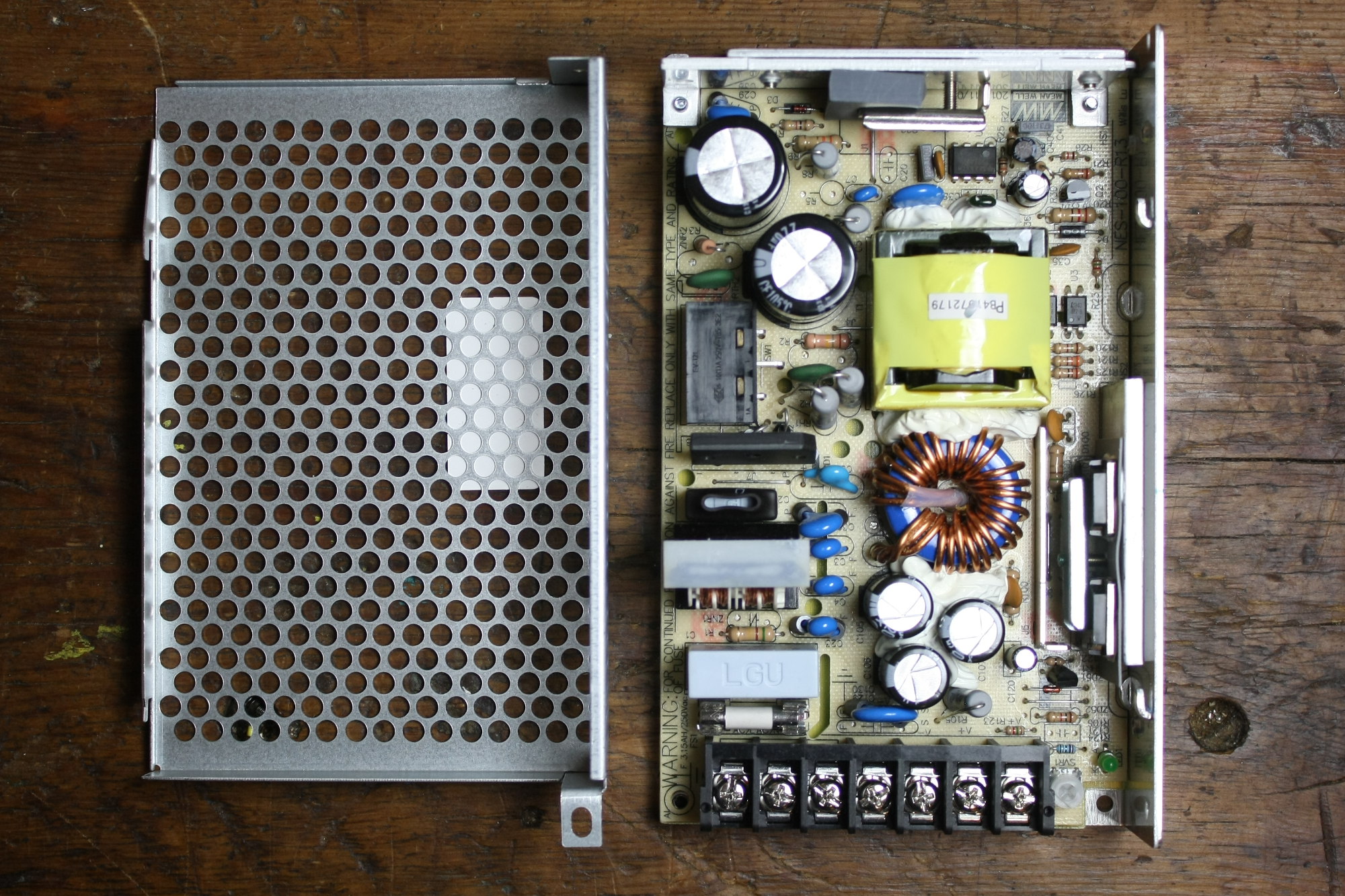
A view from above -- the design is neat and tidy. Generally, power flows from the lower left, up and around in a U shape, then out the lower right.
The circuit starts with a fuse, X cap, common-choke, another X cap, diode bridge, and high-side capacitors. This supply uses two 200V caps in series, but I don't understand how it works yet. There is a 115-230V selector switch for line voltage that plays with the bridge. Along the edge of this high voltage section, Y caps couple to chassis across a routed-out barrier, like in some of the other supplies.
The PMIC is the 8-pin DIP in the upper right, a TI 3845. It controls the switch (on the top heatsink) and gets regulation information back. Like some of the others, there's a spare winding on the transformer to power the PMIC.
After the transformer it's all rectification, storage, and feedback.
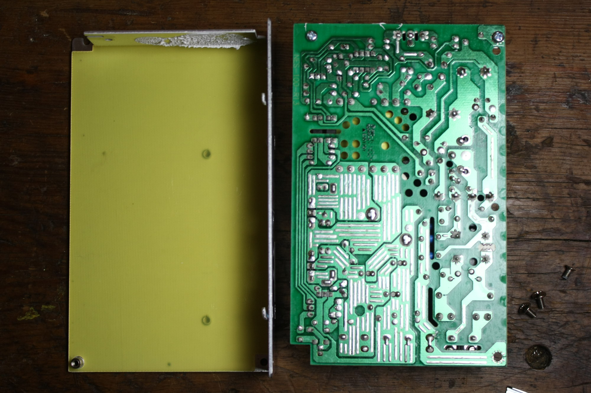
The bottom side reveals the chassis ground stub (third screw terminal from the right) that all the Y caps come to, and the slotted/drilled isolation barrier, though those holes might be for some notion of air cooling. On the low side, current is increased so many of traces have the solder mask opened for additional solder. This can decrease resistance of these traces, as explained and tested by Dave of EEVblog in Episode 317 - PCB Tinning Myth Busting.
I also found it interesting that they put silkscreen on the non-component side, but not for aesthetic reasons! If you look closely there are black lines drawn between some of the pins. I suspect this is to aid in the wave soldering process to prevent bridges.
Electrical tests
A lot can be determined from looking at layout and identifying name-brand components, but it doesn't tell much about how good the supply is at generating DC. It's not really in the scope of this article, but I wanted to touch on a few key qualifications of a power supply. The manufacturer tested them at the factory, but how rigorous were they?
Load Regulation
How good is the supply at controlling its output voltage for various loads and input conditions? Does the voltage output of the supply change with different loads?
This can be measured by using Ohm's law to determine resistances that can test any gradient of loads within the supply's range.
Output Ripple
The supply switches at a high frequency so the output must have some ripple. How much is it? Are the downstream components capable of dealing with that ripple?
This can be measured with an oscilloscope and presented in units of voltage or as a percentage. Set the scope to AC coupling with trigger at zero, and use the cursors to get a peak-to-peak value.
Transient Response
If the load suddenly changes, what happens to the regulation? How long does the supply take to regain control of the output?
Use a low-bounce switch to switch in a near-rated load. The voltage will sag, prompting the PMIC to increase duty cycle/frequency. The output can overshoot the target voltage, causing a potentially harmful spike on the line. This can be captured with an oscilloscope.
Efficiency
The goal is to make the supply 100% efficient, but that's not realistic. In fact, efficiency may only be rated at a peak, and at other operation points it could be substantially lower. This is important because extra power lost in the supply costs money, and more importantly, creates heat.
A power supply's efficiency is measured by dividing the output power by the input power, over the operating load range of the supply.
Switching Frequency
What frequency does the supply use to generate the output? Is it fixed in a range, or wild depending on load?
Set up an experiment to measure output ripple, and make a chart of frequency vs. load, or vs. input voltage, or whatever conditions the supply is expected to operate within.
Environmental Screening
Does the power supply work at all temperatures it's rated for? A common thing to happen at extreme temperatures is that a power supply will fail to come up. It might work once going, but will never start. Have you ever had a device that works fine indoors but won't turn on while cold? Even though it works at room temperature, some component has probably failed.
This may be out of the realm of hobby for most, but the test is valid. It's performed by running all the other tests inside an environmental chamber at various temperatures.
You may start to see that number of tests required to qualify a thing gets exponentially bigger when adding parameters to modify. High-quality power supplies may have gone through months of tests before they were qualified.
Conclusion
I've really only touched on the basics. I wanted to go through the process of testing these supplies, but it wasn't in the scope. Perhaps another Enginursday will feature some of the data.
I hope you've found this informational and are now able to identify some of the components you may find in supplies, and have a better understanding of what they're for. I learned a bit myself by opening some up, and hope to help bring high-quality, medium-priced supplies to the storefront in the future. Let me know what you think!


I have to buy most of my power supplies from a different vendor because Sparkfun doesn't offer higher quality options! I would love to save on shipping ;-)
Nice article! I also open my toys, specially power supplies. Those spring contacts in the Google supply were common in Nokia cellphone chargers of yore. Also, I remember UL was for Underwriters, not Universal, but maybe they changed names. I love to find "hidden treasures" in supplies. I serviced one that had a small, green LED (smaller than a 3 mm one) hidden beneath cables and components. The case didn't even had a window for it so it did its work of "power on" indication, but no one will ever see it. If you want a perfect example of a supply missing the "good" corner of the mgmt. triangle, open a cheap clone of the Apple cube charger. I was terrified to see how many ways of starting a fire it had!
I have seen those Apple cube knockoffs, terrible! Apple did a lot of work in order to both pass their compliance tests and make a sleek looking product. I can't imagine trying to fit a fast cheap design into a space that small.
Thanks for the correction. It is "underwriters", I goofed.
A couple of years ago, in needing of an automotive car charger, I picked one up at a discount store. Although I don't have definitive proof, I ended up poor battery performance down the line. It certainly could have been the phone, but I have always wondered. More so that charger eventually stopped working, the wires in the cord were extremely thin and eventually broke near the plug for the phone.
That also reminds me when I used to do automotive electronics installations (radios, subwoofers, etc.). We would often get customers that bought amp wiring kits bought off of eBay or discount stores so they could save costs. I always thought the more expensive kits met the gauge of the wire at a minimum, whereas the cheaper versions seemed to include the outer insulation jacket in their gauge number. Even the insulation jacket seemed a bit thicker.
Question: [As someone who isn't an engineer, or has stepped foot in an engineering class] Do you think open source allows more coverage of the engineering triangle? I could see that one of the benefits of open source is that something can still be designed quickly, designed well (how often have you taken a product and thought you could design better, with or without some flaw), and improve these without sacrificing costs, or finding alternatives that may reduce costs (I'll exclude the idea of group purchasing power). I would think the Arduino is a good example (please correct me if I'm mislead), but there are so many clones now. The Sparkfun Redboard for example, not to mention all the counterfeit Arduino (and Sparkfun) boards you can get at a fraction of the cost. That's at least how I see it, but I would like to hear from those of you closer to the subject.
"This supply uses two 200V caps in series, but I don’t understand how it works yet."
Two equal capacitors in series will double the voltage tolerance, but halve the capacitance. Two capacitors in parallel will keep the same voltage tolerance, but double the capacitance. It doubles the voltage tolerance (each capacitor sees "half") as long as the capacitors are equivalent (same ESR, leakage, capacitance, etc) but the equation gets more complex (similar to parallel resistors) if they are dissimilar.
Sort of. The two capacitors are necessary when a voltage switch is used like this. When using the 115V setting the switch reconfigures the bridge and input capacitors into a voltage doubler circuit. Because of this everything else downstream doesn't have to be reconfigured for a lower input (compared to the 230V input). They appear in series but there is a connection to the common point coming from the input (switch) in the doubler configuration. (I believe it's called a Delon circuit). Creative trick.
In the description of the schematic, you say "AC power from the line is regulated and stored in a large capacitor"... Dont you mean "AC power from the line is RECTIFIED and stored in a large capacitor"? Either that, or I know less about this stuff than I thought I did, which I didn't think was possible... :-)
Yep, it's not regulated, it's rectified. I'll fix that.
Thanks!
OK.. I'm definitely not an "analog electronics" kinda guy (much happier in an arduino ide or even troubleshooting old fashioned 74 series logic) but I was thinking that must be a very special kind of capacitor to store AC.. :-)
One thing you need to mention is whether or not a unit is LEGAL. The FCC sets limits for spurious signal generation, and one would expect that a unit with the FCC logo would not interfere with other services such as Amateur Radio. But it's much cheaper to print the FCC logo than it is to engineer and build a legal gizmo, so many of the shady outfits in China just print the logo, they are not LEGAL and they pollute the airwaves.
This is not limited to switching power supplies, grow-lights from Home Depot are notorious offenders, and some of the cheap LED solutions are also bad actors. The FCC does not seem to anymore have the resources to patrol against the bad actors, but they do respond to complaints. This doesn't work very well against some shady outfits as they operate under many company names and addresses.
Here's a great tutorial/article on how switching power supplies. http://www.hardwaresecrets.com/anatomy-of-switching-power-supplies/1/
Hello,
Good to see that you are addressing this issue. I have a few tips/comments, though:
MeanWell is well accepted PSU brand, they make pretty solid industrial supplies. Not as good as Lambda, but generally way above the average junk. However, it should be made clear that those are industrial supplies, not something to be sold to beginners to power their toys with. The supplies lack insulation and safety features for that - e.g. the freely accessible mains terminals or lack of proper cover, because these are meant to be built into an enclosure.
Please, make a follow-up and explain why some of these supplies are good or bad. Things to look for when someone wants to check their cheap supply. Creepage distance, clearances between the parts, insulation, presence (or lack of) filters and PFC (switchers lacking input filters and PFC are illegal to sell in EU now, they wouldn't pass compliance testing).
I would also mention things like insulation of the main transformer. That is difficult to see, but I would bet my hat on the fact that the cheap 12V/5V supply is a deathtrap because of poorly insulated windings. The cheap supplies often rely only on the enamel insulation to separate the mains wiring from the secondaries, instead of having proper insulation layers between the windings. All it takes is a bit of wear and the output becomes live. Please, don't sell these cheap junkers, someone may get hurt or a house be set on fire.
From the less critical points - check things such as output regulation (is there a separate regulator per rail or only the PMIC on the primary?), quality (or lack of it) of the output caps (poor/cheap caps = high ESR = noisy output and rapid failure).
I think you must be an industrial design engineer! I did mean to put that the meanwells (with exposed components and no ingress protection) are meant for sales to OEMs.
I got curious so here's the inside of the transformer:
I'm not sure the characteristics on this yellow tape. Probably some Kapton-like substance.
We've got:
Though they kinda fell apart when I was counting them so the ratio on the output coils could be wrong. I don't have a hipot generator to test the thing (we don't design line supplies internally), but I wouldn't call it a deathtrap. I've taken generations of these supplies apart (this one is rev A11) and the design is consistent, just low cost.
Thanks for commenting!
I use the meanwell ones pretty frequently in devices I build, and they've been bulletproof. They produce pretty clean power and despite living near some pretty powerful radio and TV station towers they have done a reasonable job at noise rejection. Most of them come with a tiny plastic shield for the barrier strip to prevent you (the maker) from zapping yourself inside the case when testing or whatever (no way is it safe for "civilians" to touch but a nice added touch). They have been pretty thermally stable, and a few times I've tested their max current (oops) and they delivered (and I have the slagged stepper drivers to prove it)...
Hello,
LOL, I am not an industrial design engineer, let's say that I am bit more experienced hobbyist :)
Re that transformer - it is better than I thought, at least there is the insulating tape (I have seen many of these cheapo PSUs without!). However, I would have expected the primary connections to be better insulated/sleeved so that they are protected against abrasion (the enamel alone is not good enough there). Check out the transformer in the Apple charger to see what am I talking about: http://www.righto.com/2012/05/apple-iphone-charger-teardown-quality.html
In addition, the winding wire isn't tripple insulated, which is, apparently, a requirement for passing UL certification (which it doesn't have, obviously). So all it takes is a power surge for the windings to arc through the tape and BOOM.
I also doubt that the FCC mark is legit, because the PSU lacks any filtering - thus will not pass any EMC testing. And the fake CE ("China Export", ehm ...) you have mentioned.
A better quality transformer wouldn't cost all that much more and be a lot safer. I think pinching pennies on mains power supplies is a really bad idea - lives and property are at stake. Unfortunately, many stores even here in Europe are selling similar crap. Please, do better and don't import these things. They are cheap, but only until someone gets hurt and you get sued ...
I have one of those cheapo supplies, and mine stopped burned itself out as well :-(