Enginursday: Voltage Regulator Temperature Mobile App
We've created an iOS and Android app that calculates if the power requirements of a linear regulator cause the temperature of the device to rise to unsafe, component-damaging levels.

When a design needs an inexpensive, simple and low-ripple voltage supply, a great choice is a linear regulator. These benefits come mostly at the cost of efficiency, which is lost in the form of heat. How does one know if a simple linear regulator can safely operate in a system, how much power is wasted, or how much heat needs to be managed? We've created a simple tool that calculates this information for you.
Model of a Linear Voltage Regulator
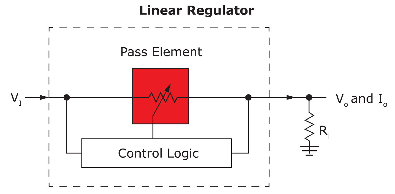
Figure 1: High-level model of linear regulator
Figure 1 shows a high-level model of a linear regulator. It consists of a resistive pass element that is controlled by some logic to keep the output voltage at the desired value. At this level only three values are really needed to feed the model and get values for power lost and heat generated: the input supply voltage, the desired output voltage and the current being drawn by the load. That’s all that is required to determine values to necessary precision.
In reality, the pass element isn’t normally a potentiometer as shown, and the control logic is more than a magic box.
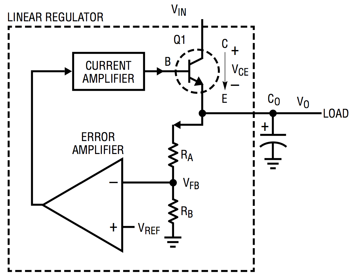
Figure 2: More detailed conceptual model (Courtesy of Linear Technology)
A possible actual implementation uses an error amplifier to sense the output voltage of a voltage divider. The error is the difference between the scaled voltage and a precision reference. The error feeds the base of a bipolar or gate of a field effect transistor in their linear regions. The current through the divider and into the amplifier is known and can be accounted for.
The model used by this application assumes that the power used by the control logic is negligible. In reality, I’ve seen values as low as 1.5µA. Other regulators use on the order of 10’s of µAs. A low quiescent current of 10µA is only 1 percent error when drawing a single mA. Typical use cases are often in the multiple mA range and up. Since the power used by the logic is negligible, the current in is equal to the current out and only needs to be set once. The extra voltage is lost in the form of heat in the power transistor.
Regulator Specifications
The app comes with some typical values for a generic linear regulator already set. This is great for playing around and estimating, but for real applications the actual manufacturer specifications should be used. These may be tricky to find, but the best place to look is in the manufacturer’s datasheet for the part.
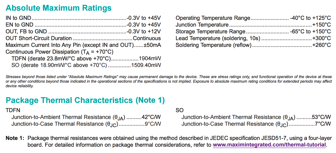
Figure 3: Example regulator specifications from datasheet (Courtesy of Maxim Integrated)
The key specs to look for are the maximum junction temperature and the thermal resistance. The resistance varies from package to package and the thermal mass of whatever the regulator is touching. For this example we will take a common use case of a regulator without forced cooling and without a heat sink attached to a four-layer PCB. The datasheet shows this thermal resistance (θJA) between the junction to ambient to be 42°C⁄W.
There are at least three values listed for maximum temperature. The part is rated to operate over the -40°C to +125°C automotive temperature range. That's not relevant to this math. The maximum junction temperature is spec'd to be +150°C. We can verify that this is a good value since later in the datasheet it is stated that the device will go into thermal shutdown at +165°C. That’s a state to definitely avoid, so there is a little margin.
Using the Application

Figure 4: Setting example specs

Figure 5: Determining maximum current allowed
At the top of the app is the familiar hamburger menu that slides the settings out from the left side. Figure 4 shows the thermal resistance of 42°C⁄W and the max junction temperature of +150°C entered. This example uses the default ambient temperature of +25°C. Swiping the settings back to the left hides them. The input voltage was arbitrarily chosen to be 12V, and the output to be 5V. The current slider was wiggled until it was right around the point where JUNCTION TEMP: XY.Z°C label turned red (@ 150°C) and fine-tuned with the steppers to the maximum point where the label wasn't red. This turns out to be 0.425A, which is wasting nearly 3W of power.
Tips
If you live in ‘Murica you are probably more comfortable with temperature units of degrees Fahrenheit. There is a setting to change the units to °F. Touch the gray Fahrenheit (°F) label. It should turn green, indicating the change has been made. Only the thermal resistance will remain in the units most of the world use (°C⁄W) since we aren't sure where to find those values in other units (°F·s⁄ft·lbf?).
The default ranges of the sliders cover a fairly large range that should work for many cases. If the parameters for a project are outside of these ranges, then the bottom section of the settings is provided as a way to fix that. There might be cases where one wants a clean 200A supply of 24V. Feeding up to ~24.021739V into a magic LDO, that range can be set. Many designs may lie in a narrow range. The parameter ranges can be tightened up to make finer tuning easier. The range of the slider is discretized because there are only so many pixels on a screen. If a value cannot be set with the slider, narrow the range or use the steppers next to the sliders to fine-tune the value.
For back-of-the-envelope type calculations, wiggle the slider near the desired value. If nothing turns red, then the application is nice and safe.
Advanced Use and Hacks
The first hack allows typing in the desired voltages and/or current to great precision. The trick is to set the desired value as the min or max for a slider setting. After that, simply swipe all the way to that extreme, and the exact value is set.
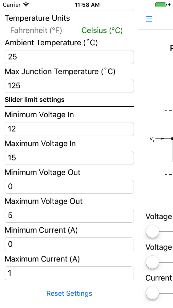
Figure 6: Setting exact values as slider extremes
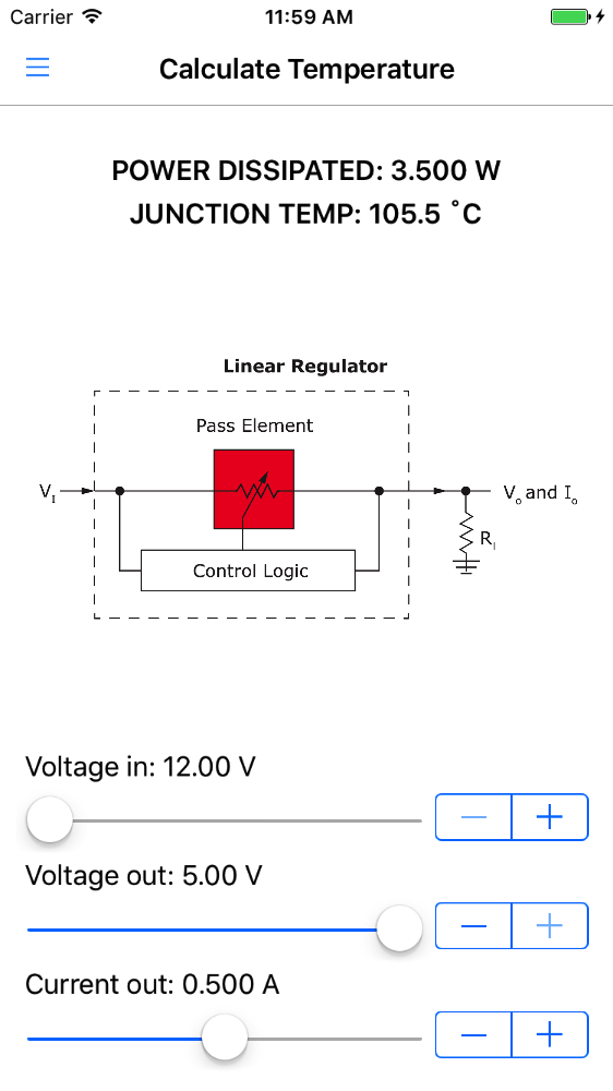
Figure 7: Using those typed-in values
The precision of the inputs on the UI is limited to 10mV and 1mA steps, but the math isn't. To come up with eight significant digits in the last section, a minute or two was spent using this hack to get that value (which is likely poor using only a simple linear model with the used assumptions).
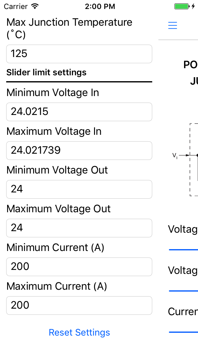
Figure 8: Excessive precision
Another ‘hack’ is too use ‘fake’ values for the thermal resistance to model heat sinks and other configurations. Sum the thermal resistances of the regulator, the junction between it and a heat sink, and that of the heat sink.
Where to Score
Want your own copy? It's free in the Google Play Store and the iTunes App Store.
Hate something about the app? Go fork yourself a copy and change it!
Have an idea for another app? No promises, but feel free to share your idea in the comments below.
Bonus
For those who have never put a mobile app into one of the marketplaces, here is an interesting clip. The following is Google’s automated testing getting an older build to crash. Interesting use of the app, but it worked to find a flaw! Both Apple and Google run tests like these when a new version is uploaded.
Fun clip of Android version crashing during development


Thanks. Fixed that swap!