Hardware Hump Day: Physical Sensors and Digital Interfaces
Learn how to control a computational program with your Arduino sensors!

This lab experiment was originally written on August 19, 2014 by Tom Igoe and last modified on September 2, 2016 by Benedetta Piantella Simeonidis. Original documentation can be found here.
One of the things I love most about working with programmable electronics is the diversity of potential outputs. As makers, we have the tools to create robots, wearables, interactive art, connected devices, musical instruments and more. While I tend more toward creating visual projects these days, I initially learned Arduino in conjunction with a creative programming and computing language called Processing. The idea was to create projects with both physical and digital interfaces building meaningful human/computer interactions.
Processing is a learning language that was first created to serve as a software sketchbook and to teach programming fundamentals within a visual context. One of the most exciting features is that it allows users to quickly and easily pull input from Arduino sensors to control a screen-based program. This is an incredible tool for game designers and applies to any projects for which a screen-based application should be controlled by a physical input. Today we will walk through the steps of serially communicating physical input data from Arduino to control a processing program.
Before we get started, I encourage you to check out Processing.org to learn more about the programming language. If you are new to programming, it is an incredible tool for learning --- especially for the visually inclined like myself. There are all sorts of resources online, including a reference page, code examples, video tutorials, library downloads and books. I also encourage you to check out "The SparkFun Guide to Processing."
Now let’s start exploring how we can use Arduino as an input for our Processing programs. We’ll start with the Arduino side of the process. Download the Processing IDE to get started.
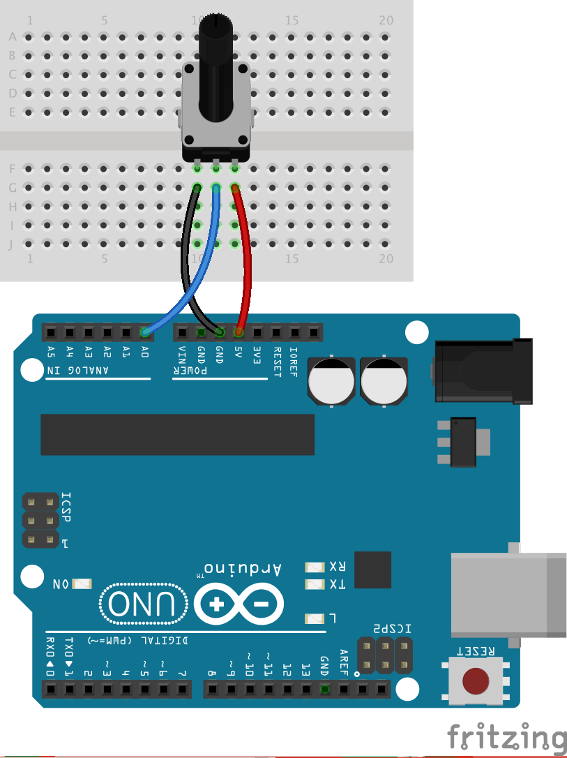
Designing a Circuit
First, build a simple circuit with an analog input following the Fritzing diagram below.
Arduino Programming
In order to program your Arduino, you will need to download the latest version of the Arduino IDE. For a more in depth view, visit our tutorial on installing the Arduino IDE. Let’s walk through the program before we upload it.
Before setup, declare your potentiometer pin.
int pot = A0;
In setup, declare your potentiometer as input and begin the serial communication void setup() { pinMode(pot, INPUT); Serial.begin(9600); }
In loop, read the analog value of your potentiometer, and then Serial Write that value.
Note: We are not using the Serial.print command but rather Serial.write. This technique will not work with Serial Print.
void loop() {
  int potValue = analogRead(A0);
  Serial.write(potValue);
}
You can also copy the entire program below and paste it into your Arduino IDE.
int pot = A0;

void setup() {
 pinMode(pot, INPUT);
 Serial.begin(9600);
}

void loop() {
  int potValue = analogRead(A0);
  Serial.write(potValue);

}
Once your program is uploaded, keep it connected to your USB port and leave the program running. We can move on to the Processing part of this process from here.
Processing Intro
Processing is similar to Arduino in its structure. Every program has two fundamental functions:
void setup(){
}

void draw(){
}
Without getting too deep into it, these two functions mirror the setup and loop functions in Arduino. In the setup function we put all the code that should only run once when we start our program, and in draw we put everything that will continue to run in a loop while the program runs. The syntax is super similar and should be easy to read. There are some differences, though, so make sure to keep the reference page available when you start writing your program.
Processing Program
In order to demonstrate this technique, we will be using a simple visual graph to show a changing value controlled by an Analog Input.
Before the setup function, we will need to import the Serial library using the following two lines:
    import processing.serial.*;
    Serial myPort;
You will also need to declare an X and Y variable. We will use these later in the program to draw a graph:
float xPos = 0; // horizontal position of the graph
float yPos = 0; // vertical position of the graph
Now let’s look at setup. We have four lines of code to include here.
Processing is a visual language and will always open a window when the program is run. The size of the window must always be declared in setup. When the program is run, a window will pop up, reflecting the size declared in this line:
size(800,600);
We need to assign a variable to the string that defines the USB port that your Arduino is connected to. You will need to replace the string below inside the quotes with the name of the port that reflects where your Arduino is connected to your computer.
String portName = "/dev/cu.usbmodem1411";
Next, we tell processing which port to listen to using the variable we created in the previous line. This is also where we declare the baud rate at 9,600, which reflects the same rate we used in our Arduino program:
myPort = new Serial(this, portName, 9600);
The last line in the setup function is the background color of our program window. This just makes it looks a bit nicer than the standard gray: background(#081640);
Now let’s fill out our draw function. First, we need to assign a color to the lines on our graph:
stroke(#A8D9A7);
The following lines will draw the graph onto your screen and animate it to clear the screen and start over once it's completely full with the visual graph.
 // at the edge of the screen, go back to the beginning:
  if (xPos >= width) {
    xPos = 0;
    // clear the screen by resetting the background:
    background(#081640);
  } else {
    // increment the horizontal position for the next reading:
    xPos++;
  }
Finally, we will need to write a third function outside of the draw function that will allow us to receive the value from our potentiometer in Arduino, and translate that into the value output of Y in our graph.
Here, we are reading myPort, which is a variable we assigned in setup to the string value of our Arduino port. The program reads the incoming value and assigns it to a variable ‘inByte’. That value is printed to the console for debugging. Finally, the variable ‘yPos’ is defined relative to the potentiometer value (the height of our screen minus the incoming value). This variable will change in value based on the potentiometer value:
void serialEvent (Serial myPort) {
  // get the byte:
  int inByte = myPort.read();
  // print it:
  println(inByte);
  yPos = height - inByte;

}
The full processing program is below to copy and paste directly into your Processing IDE. Just don’t forget to update the Serial Port in your own program to reflect the USB port on your computer.
import processing.serial.*;
Serial myPort;

// at the top of the program:
float xPos = 0; // horizontal position of the graph
float yPos = 0; // vertical position of the graph

void setup(){
  size(800, 600);
  print(Serial.list());


  // change the number below to match your port:
String portName = "/dev/cu.usbmodem1411”;
myPort = new Serial(this, portName, 9600);
background(#081640);
}

void draw(){
 stroke(#A8D9A7);
  line(xPos, height, xPos, yPos);

  // at the edge of the screen, go back to the beginning:
  if (xPos >= width) {
    xPos = 0;
    // clear the screen by resetting the background:
    background(#081640);
  } else {
    // increment the horizontal position for the next reading:
    xPos++;
  }

}


void serialEvent (Serial myPort) {
  // get the byte:
  int inByte = myPort.read();
  // print it:
  println(inByte);
  yPos = height - inByte;

}
Now all that’s left to do is hit the run (or play) button at the top left corner of your Processing IDE, and watch the graph animate and change as we turn the knob on the potentiometer.
Just like that, we are communicating. Serially.

The opportunities this technique opens up to a maker are endless. You can build games, interactive experiences, exhibitions, displays and more! My first Arduino/Processing project was a Digital Graffiti Wall, which was a ton of fun to make and even more fun to play with!
What kind of project would you design with this skill? Let us know in the comments below!


My advice (for what it's worth) is to always remember that while communication is good, reliable communication is better. To avoid embarrassment, I won't admit how many times I've had a component behave unexpectedly only to find out it was processing data that wasn't received correctly. So as I've gotten older and (arguably) wiser, I have forced myself into the habit of always sending data in packets - even if only sending a few bytes of data. The packet usually consists of a header to identify the data, a length field to indicate how much data is being sent, and a CRC or just a simple checksum so the receiving node can make sure everything came across uncorrupted. It may seem like overkill at the start of a project, but I've found that if you lay the foundation early for reliable communication, adding data later almost becomes trivial.
Great project Feldi, I learned something new and the lesson helps understand another project I'm working on. Thanks for continuing to share despite being mansplained and nit picked on ticky tack details for many of the projects you post. Keep the posts coming :)
Thanks, friend! I appreciate the support :)
This is also available in the Arduino environment under: File>examples>communication>graph. You just need to match the port to the port your Arduino is on. I also like the Processing examples in: File>examples>libraries>Serial>simple read (and simple write).
The fritzing diagram was accidentally left out.
This has been updated, thank you!