Solar Cooking with Maximum Efficiency
Using the new SparkFun ProDriver, a pair of stepper motors and some mirror acrylic, I created a solar cooker that tracks the sun as it crosses the sky, guaranteeing optimal efficiency from your solar barbecue.

Twice every year, in February and September, the world’s top fashion designers, as well as younger up and coming designers, descend upon NYC to show off their designs for New York Fashion Week. Designers will easily spend six figures to get the set and venue to look exactly the way they want to best showcase their collection, in a show that usually lasts for no more than 20 minutes. After that, much of the materials are reused or recycled, but some of it deemed not reusable simply gets thrown out. This can be a maker’s dream.
I spent seven years working with one of the top companies in NYC responsible for designing, building and installing everything in those fashions shows that wasn’t clothing - the backdrops, the prosceniums, the runways, the lighting. We used every conceivable material, so I had access to lots of those materials, saving them from the dumpster and giving them new life in a string of hare-brained projects.
This is where I built my first solar hot dog cooker. To say it was primitive in its construction would be overselling it. Some scraps of wood, a scrap of mirror acrylic, and for the skewer a steel rod that I wiped off with a paper towel, and that was it. To pan the unit, I just dragged it slightly to the west. And to tilt, I had a piece of wood that I just screwed into the side of it, and adjusted by screwing it in at different heights. Now, years later, I decided it was time for an upgrade.
Me, upside down and somewhat distorted, in the reflection of the SparBcue solar cooker
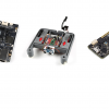
Luckily, with the release of our new SparkFun ProDriver, controlling the movement with a pair of 125 oz.in stepper motors was incredibly simple. Four photocells measure the light discrepancies across both the X and Y axes, and that information is used to keep the unit pointed directly at the sun.
As for actually cooking the hot dogs (or whatever you decide to throw on the skewer) we rely on the beauty of the parabola. The sides are ¼” plywood with minimal 1”x2” framing, and ⅛” mirror acrylic bent into a parabolic arc, with the skewer at the focal point. I laid out the points on one of the sheets of plywood, then clamped the two sheets together and drilled small holes along the arc, with another set of holes slightly inside the first. Through these holes I put small finishing nails to hold the bent acrylic sheet in place.
My original layout sketch for the parabolic arc for my Solar Hot Dog Cooker v.1.
A basic lazy Susan swivel plate is used to pan the device from east to west, belt driven from one of the stepper motors. For tilt, a threaded rod on the second stepper motor changes the angle. This is perhaps more precise than this build requires, but seemed the simplest way to achieve the necessary movement on this axis. A single hinge point at the front and dual hinge points at the rear allow for proper tilt, with the dual rear hinge points guaranteeing that the threaded rod remains in alignment throughout the entire range of the SparBcue.
Hinging the motor mount as well as the threaded T-nut receiver maintains alignment of the threaded rod.
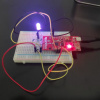
To track the sun, I’m using four photocells, one on each corner of the cooker, in 3D-printed enclosures. The application is quite simple - take measurements from all four sensors, then do some averaging. If the top is darker than the bottom, tilt up until they’re once again evenly illuminated. Then do the same thing for left and right. I had tried a build like this several years ago using a pair of servo motors, but this was the first time I had tried it on this scale, and with stepper motors. It actually works quite nicely.
/*
  SparBcue by Rob Reynolds @ SparkFun 2020
  A Sun Tracking Solar Hot Dog Cooker

  This board uses two SparkFun ProDrivers and two stepper motors
  Feel like supporting open source hardware?
  Buy a board from SparkFun! https://www.sparkfun.com/products/16836

  This code is free to use, alter,and distribute, but if you find it useful
  and we meet some day at the local, you buy me a beer. (Beerware License)

  Hardware Connections:

  ARDUINO --> PRODRIVERs
  D8 --> STBY   PRODRIVER1 and PRODRIVER2
  D7 --> EN     PRODRIVER1 and PRODRIVER2
  D6 --> MODE0  PRODRIVER1 and PRODRIVER2
  D5 --> MODE1  ***PRODRIVER1 only***       (LATCH PIN 1)
  D4 --> MODE2  PRODRIVER1 and PRODRIVER2
  D3 --> MODE3  PRODRIVER1 and PRODRIVER2
  D2 --> ERR    PRODRIVER1 and PRODRIVER2

  ARDUINO --> PRODRIVER2
  D9 --> MODE1  ***PRODRIVER2 only***       (LATCH PIN 2)

*/

    #include <Servo.h>  //Library to manage Servo

#include "SparkFun_ProDriver_TC78H670FTG_Arduino_Library.h" //Click here to get the     library: http://librarymanager/All#SparkFun_ProDriver
PRODRIVER myProDriverVert; //Create instance of the vertical stepper motor
PRODRIVER myProDriverHor; //Create an instance of the horizontal stepper motor

#define myProDriverHorLatchPin 9; //The latchpin for the 2nd driver must be defined.     (The first driver latchpin is predefined.)

//Assigning photocells
int pctopl = A2; //top left LDR green
int pctopr = A1; //top right LDR yellow
int pcbotl = A3; // bottom left LDR blue
int pcbotr = A0; // bottom right LDR orange

int tol = 50; //Set tolerance so that minor light difference don't trigger movement.     Adjust as needed.

Servo skewerServo; // A continuous rotation servo spins the skewer

int pos = 90; //This sets speed of continuous rotation servo to 0

void setup() {
  Serial.begin(115200);
  Serial.println("SparkFun ProDriver TC78H670FTG Sun Tracking Solar Cooker");

  skewerServo.attach(10); //Attach the servo to pin 10

  // myProDriver2
  // Note, this must be setup first because of shared lines.
  myProDriverHor.settings.controlMode = PRODRIVER_MODE_SERIAL;
  myProDriverHor.settings.mode1Pin = myProDriverHorLatchPin; // latch pin
  myProDriverHor.begin(); // calling this first ensure latch pin 2 will be low     during other future .begin()s

  // myProDriver1
  // default latch pin is D5, so no need to change here
  myProDriverVert.settings.controlMode = PRODRIVER_MODE_SERIAL;
  myProDriverVert.begin();

}

void loop() {

  skewerServo.write(75); //spin the skewer forever

   //capturing analog values of each photocell
  int topl = analogRead(pctopl); //Read top left photodiode
  int topr = analogRead(pctopr); //Read top right photodiode
  int botl = analogRead(pcbotl); //Read bottom left photodiode
  int botr = analogRead(pcbotr); //read bottom right photodiode
  // calculating average
  int avTop = (topl + topr) / 2; //average of top photocells
  int avBot = (botl + botr) / 2; //average of bottom photocells
  int avLeft = (topl + botl) / 2; //average of left photocells
  int avRight = (topr + botr) / 2; //average of right photocells

  // Print values for testing
  Serial.print("Average Left: ");
  Serial.println(avLeft);
  Serial.print("Average Right: ");
  Serial.println(avRight);
  Serial.println("Average Bottom: " + String(avBot));
  Serial.println("Average Top: " + String(avTop));
  Serial.println();

  if ((avTop + tol) < avBot){

    myProDriverVert.step(50,0); //Turn CW
    delay(10);
    Serial.println("Move Up");
  }

  else if ((avTop - tol) > avBot) {

    myProDriverVert.step(50,1); //Turn CCW
    delay(10);
    Serial.println("Move Down");
  }

  if ((avLeft + tol) < avRight) {

    myProDriverHor.step(50,0); //Turn CW
    delay(10);
    Serial.println("Move Left");
  }

  else if ((avLeft - tol) > avRight){

    myProDriverHor.step(50,1); //Turn CCW
    delay(10);
    Serial.println("Move Right");
  }
  Serial.println();

  delay(5000); //Give it a little time between readings.

}
When aligned to the sun, you can see beams of light, as well as shadows from the nails, all converging on the focal point.
ISSUES AND UPDATES
During the construction, I learned that one of the two 125 oz.in stepper motors was faulty. As I knew I wouldn’t be able to get another before the build had to be completed (unless I wanted to shoot the video with the device untested), I went with a slightly smaller stepper motor with less torque. While it did work, it made a pretty terrible sound that indicated that it probably wouldn’t be a very good long term solution. As soon as I get another 125 oz.in stepper motor, I’ll swap that back in.
The SparBcue is currently powered by a 5V lithium ion battery pack for the RedBoard and continuous rotation servo, and a 12V battery to power the two stepper motors. The steppers need a lot of torque, and therefore a lot of power, so I don’t know that I’ll be able to change out this power source. However, to run the board, I’m planning on swapping out the battery pack with a solar panel. I also need to do a little work on the gear on the skewer. While the gears themselves are fine, their attachment to the skewer is questionable at best. I'm also considering adding a potentiometer to allow for adjustment of the tolerance on the fly. An additional pair of potentiometers might be useful for getting a rough focus towards the sun before engaging its tracking. Hey, if something's worth engineering, it's worth overengineering, right?
Happy cooking, and Happy Hacking!
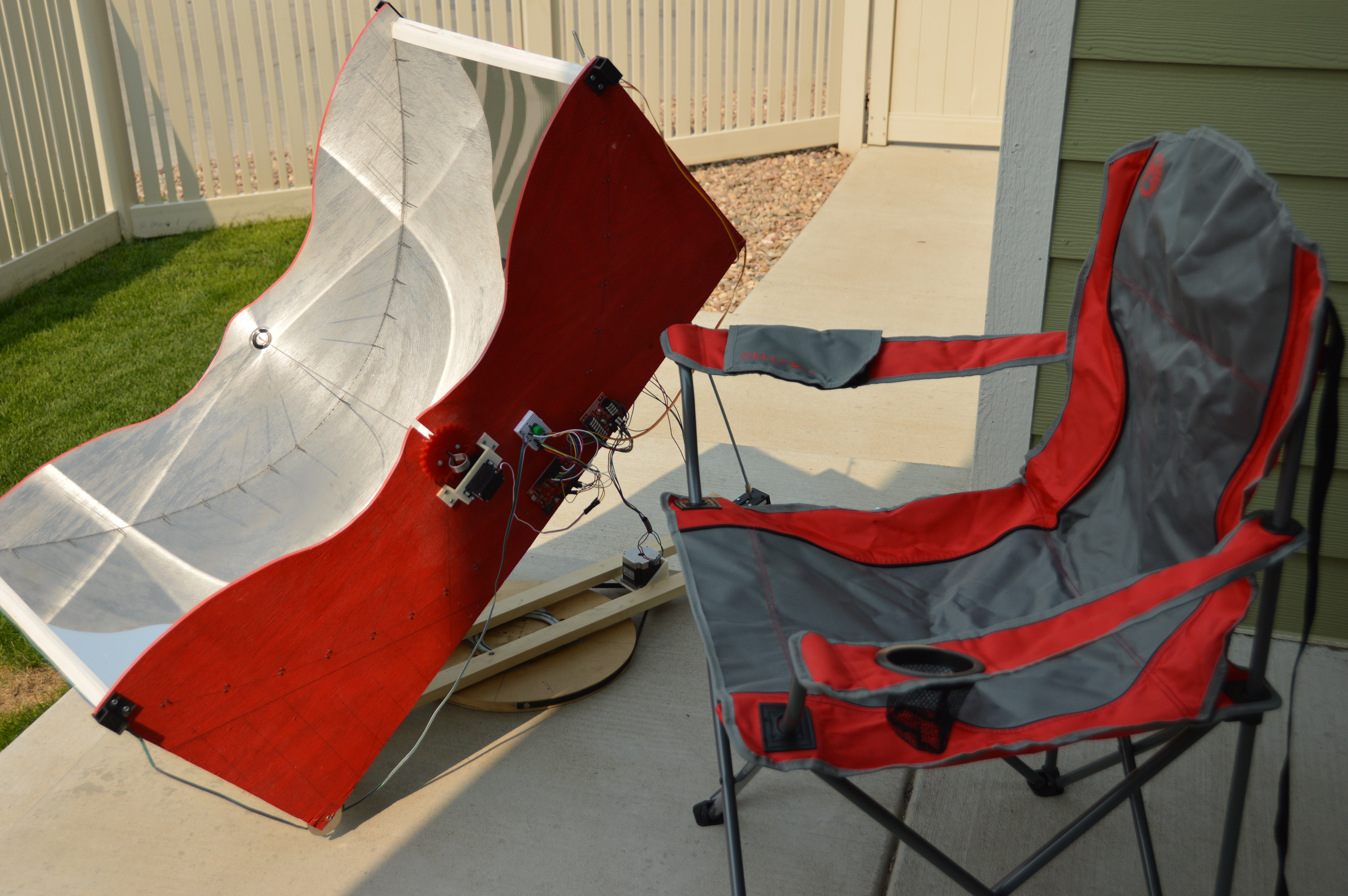
The perfect time of day - SparBcue in the sun, chair in the shade, and cold drink in the hand (you'll have to take my word on that last one).


Great article! But first a minor "nit": since I didn't recognize the word "prosthenium" I asked Google to define it, and it found many definitions for the word "proscenium", which sort of seemed to fit what you were saying. Spelling error, maybe?
As for the solar panel, I'd kind of be inclined to keep the 12V battery and use the solar panels to keep it topped up -- the battery can provide a lot more "surge power" than the solar panels alone.
And I still think you should have done the video using one of the new Raspberry Pi cameras! ;-)
Kinda reminds me back in Engineering school when the prof told us about cooking hotdogs using a couple of nails (careful about the material of the nails here -- do NOT use galvenized!) and a "suicide cord" (alligator clips on one end, and a plug on the other) to cook hotdogs. A few years later there was an "appliance" that used just this technique, albeit with plastic housing to make sure you didn't touch the electrical contacts. Admittedly, this idea sort of falls under "don't try this at home"... I've never actually tried it.
Absolutely right, it was just a spelling error. "Prosthenium" sounds like a theatre wall fabricated entirely out of artificial limbs! Agree with you about the 12V, it's definitely needed to power the stepper motors. And I've heard about the suicide cord hot dog cooker too, but like you, that's one I've never tried.
This is amazing idea solar cooking I will try it on my pizza
Oh, come on, Rob. This just begs for one of your videos.
You're in luck! This is just the project write up for the video he made in last week's Friday Product Post.