How to Make a 3D-Printed D&D Rotating Puzzle Room With OpenForge2.0 and MicroMod
Follow this tutorial to build a Rotating Puzzle room for your Dungeon. This project incorporates parts from the OpenForge2.0 project with a few additional 3D-printed components and SparkFun's Qwiic and MicroMod systems to make a rotating puzzle room that can be activated by placing a magnet on the "secret" tile or remotely using a computer, phone, or tablet.

Following in Rob's footsteps, I decided to take a stab at modifying some of Devon Jones's OpenForge2.0 tiles to create a kinetic, interactive puzzle room that any sufficiently handy dungeon master can incorporate into their campaign! The video below shows the basic assembly process and functionality, and there are more detailed instructions below if you want to make your own!
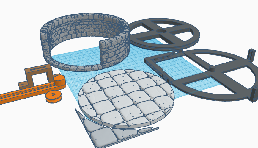
After printing out all of the parts for the build, it's time to get everything painted to your liking. I printed out my parts using black and gray PolyMaker Polylite PLA, and then painted the walls and floors with black and white acrylic paint using a sponge for a marbled, stony texture.
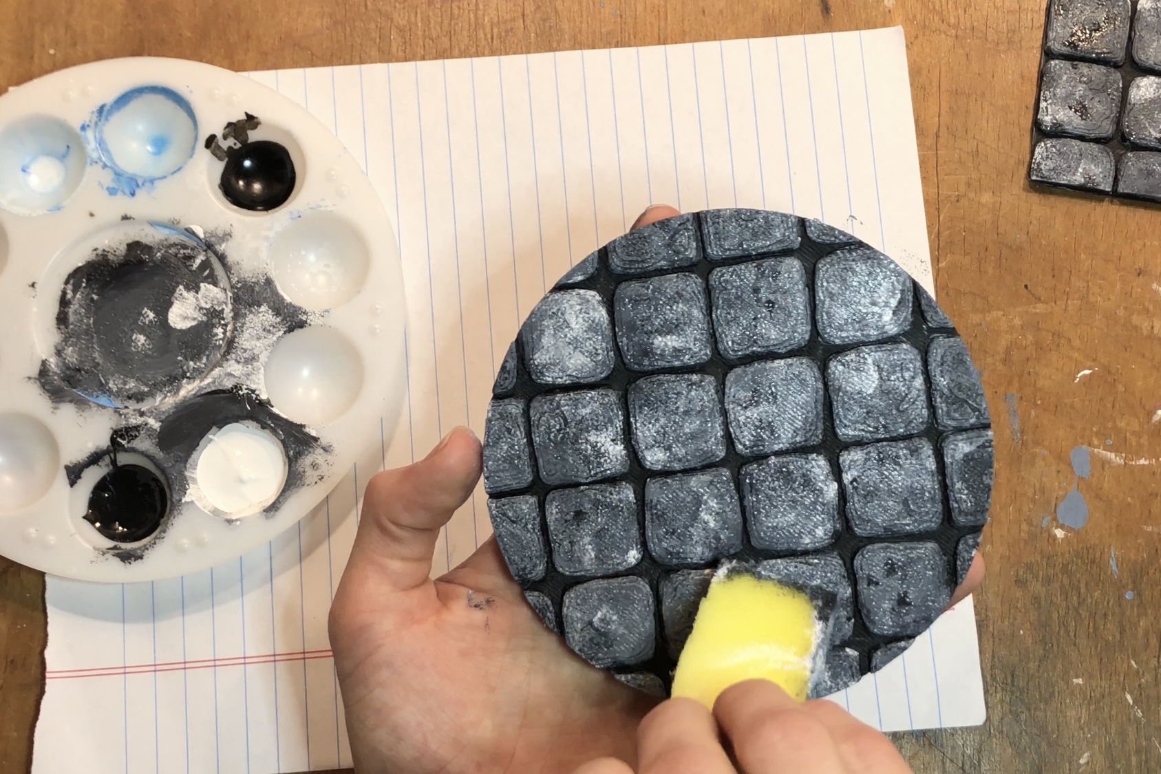
Painting the dungeon floor with a sponge to achieve a stony texture
Next, I attached the normal walls and floors to their bases using a hot glue gun. Don't forget to attach the tiny triangular corner piece to the rotating room base (I forgot to include a clip of that step in the build video).
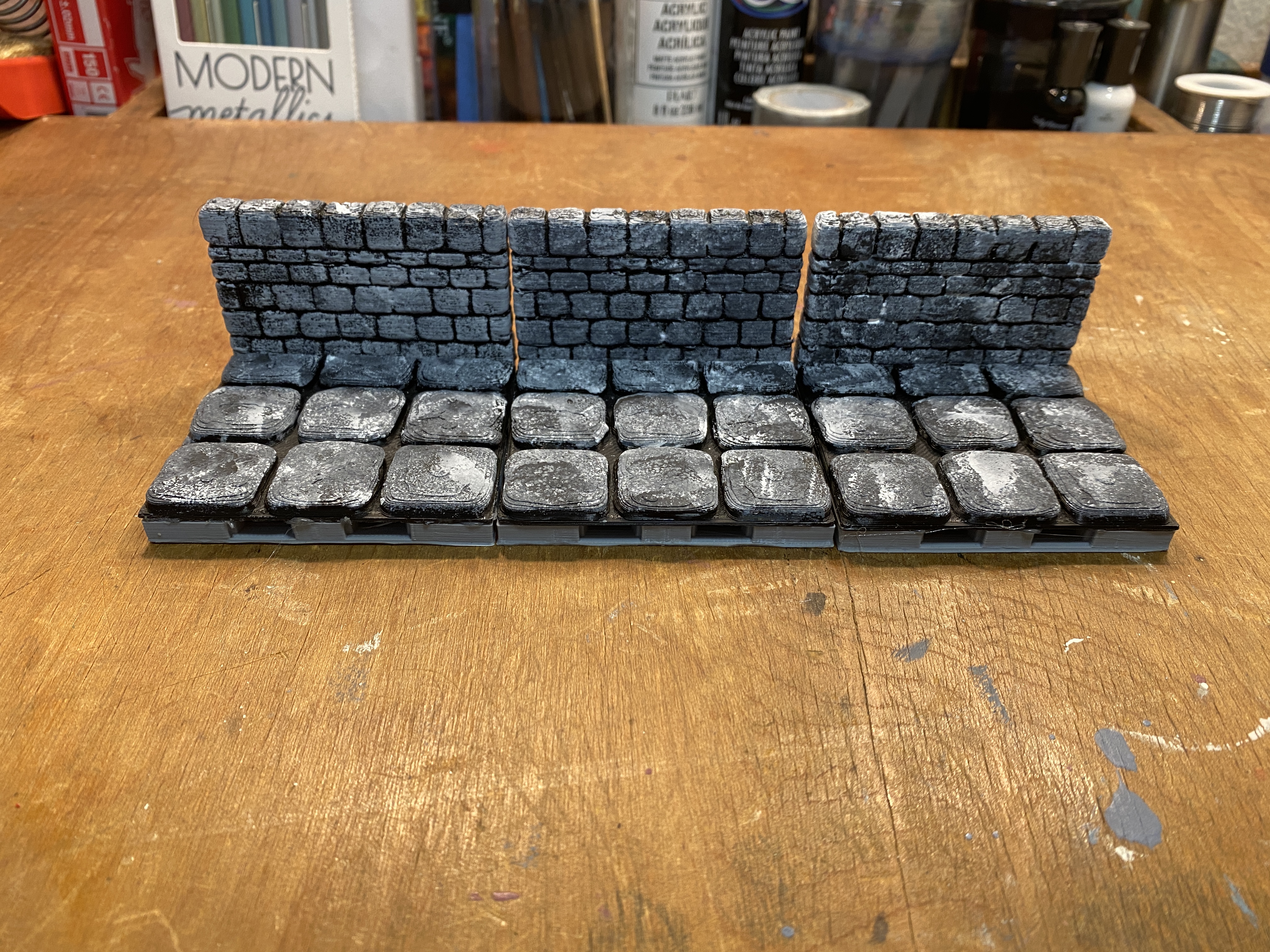
Assembled 3x3 wall tiles
With the 3x3 tiles assembled, it’s time to put together the rotating room. First, snap a 608 ball bearing (skateboard bearing) into the center hole of the round base piece. Then, grab the base part with the corner piece and snap the bearing onto the center pivot. The round base should now rotate freely.
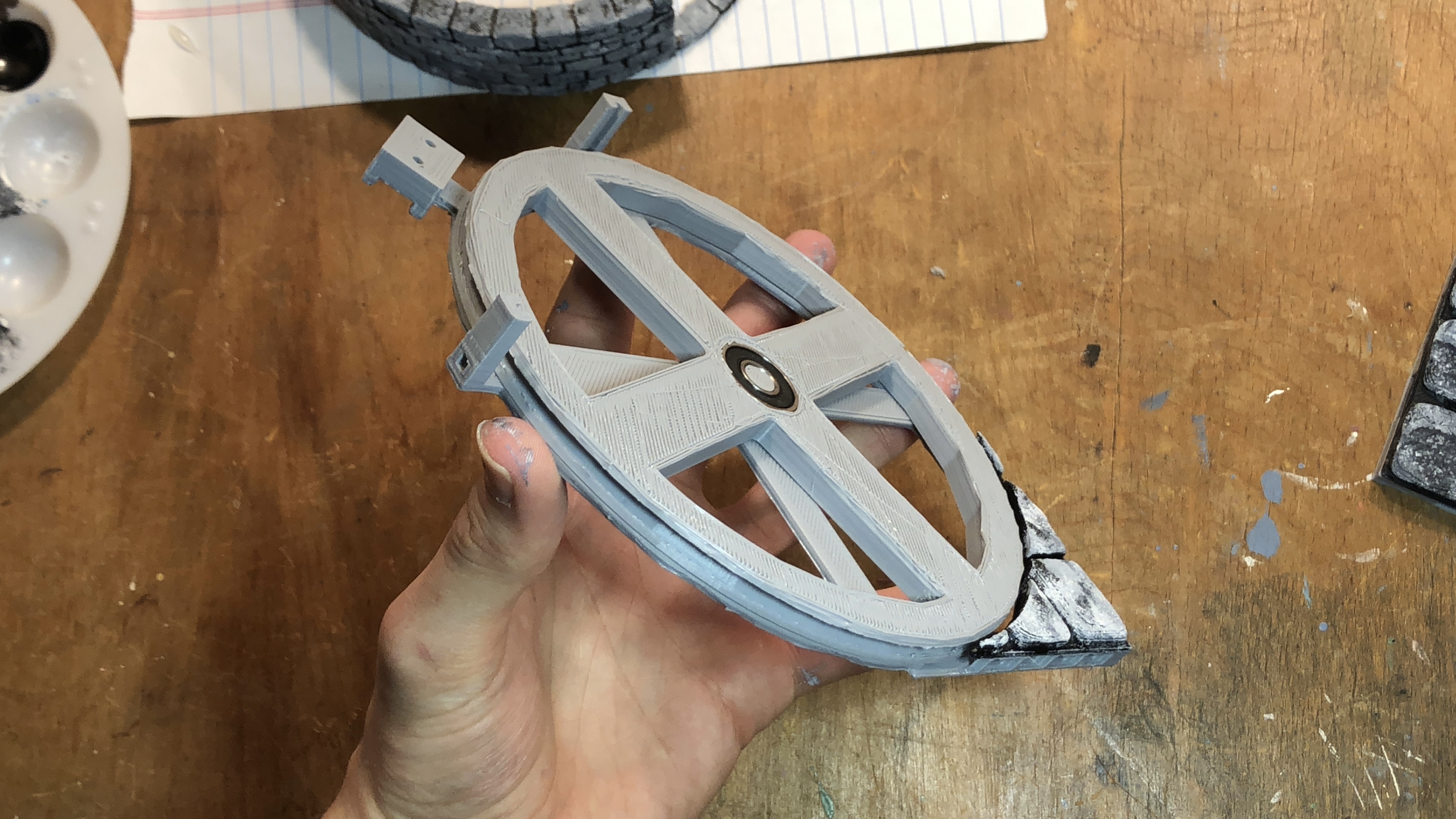
Rotating base assembly
Now you need to prepare the hobby motor assembly. Grab the U shaped motor mount piece and insert a 4-40 hex nut into the slot on the underside of the part, securing it in place with a ½” 4-40 screw. This screw will slot into the hobby motor’s mounting hole and prevent it from sliding laterally out of the mount. At this point, I also snapped the drive pulley onto the motor’s shaft.
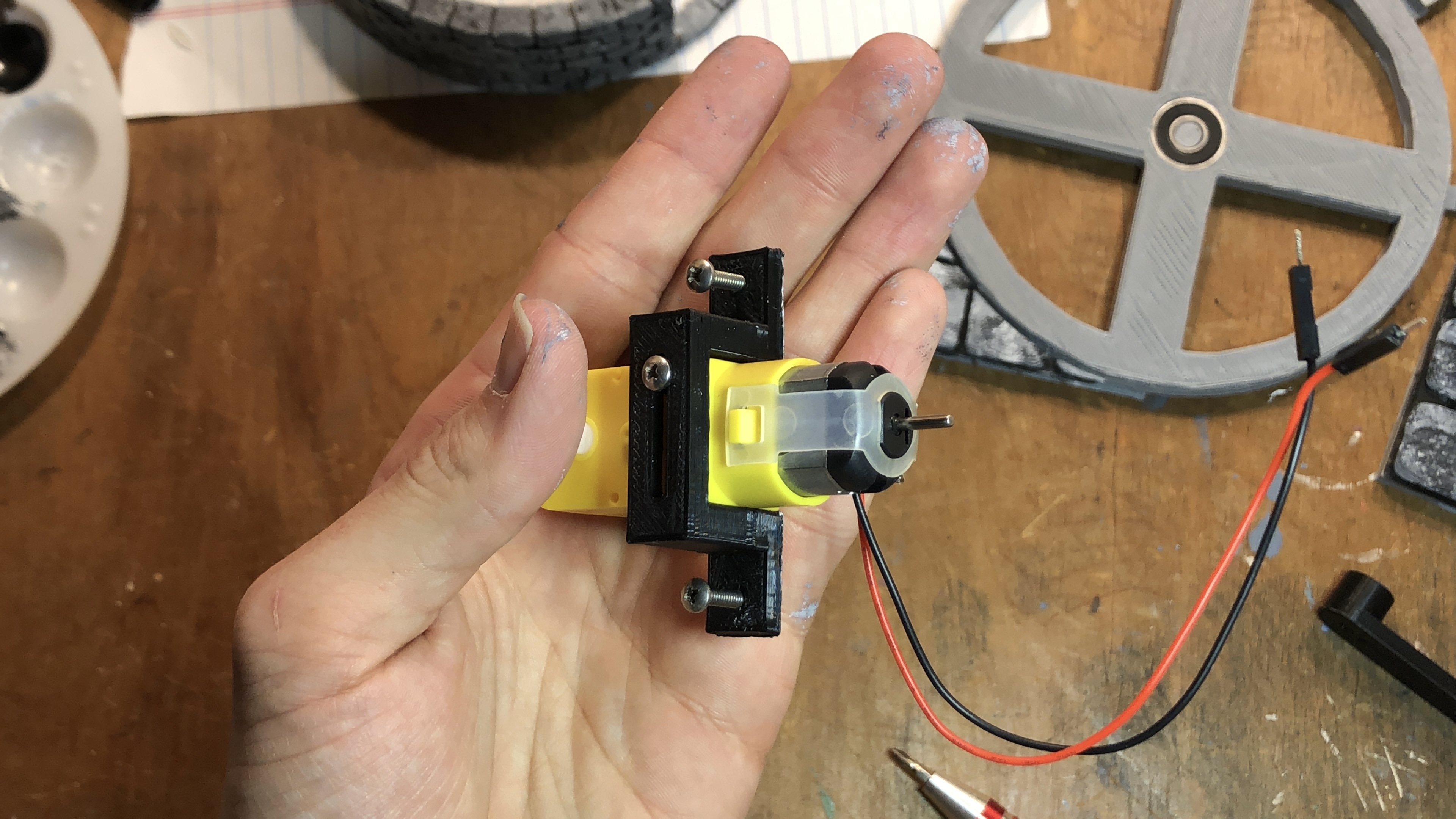
Hobby motor mount (top side)
After assembling the motor I put a couple more screws into the mount and attached the motor to the slotted arm piece by inserting a couple more hex nuts into the groove on the underside of the part and sandwiching everything together as shown.
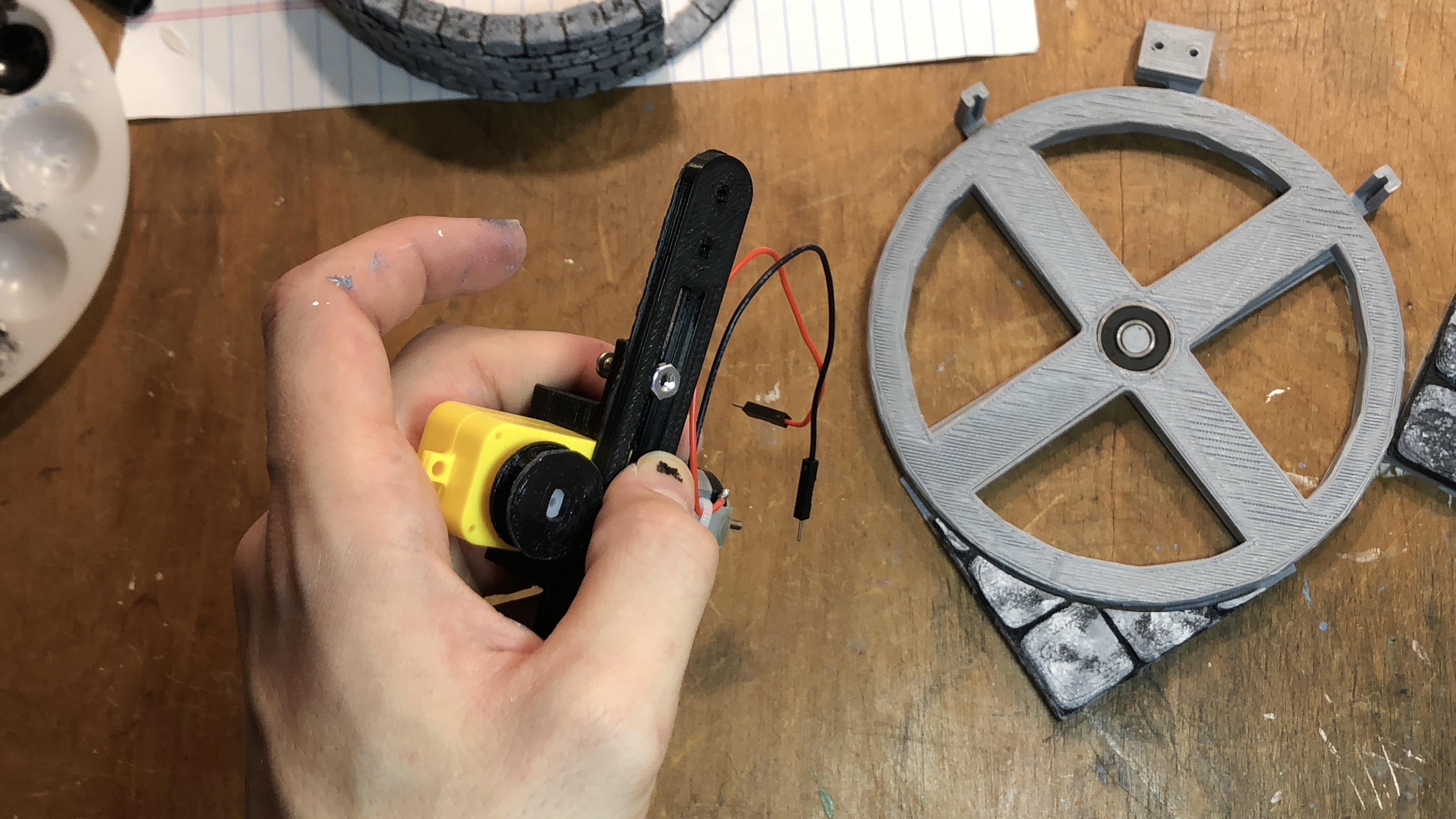
Completed hobby motor mount arm subassembly
The motor assembly can now be attached to the rotating room base with two more 4-40 screws. Once it’s attached, connect the drive pulley and the round base piece by winding some string (I used red embroidery floss) one time fully around the drive pulley, and then around the larger pulley base piece. A large rubber band would also work, but I didn’t have one on hand. If you use a string as I did, the motor can be repositioned to put tension on the string. I plugged the motor into the GND and 5v pins on a Redboard I had lying around to make sure the pulley would turn as expected.
Testing the pulley's rotation
With the motor mounted and a freely rotating base piece, the next step is to attach two reed switches to the mounting slots on the base piece. I held mine in place with some hot glue. One lead of the switch should protrude from the hole on the reed switch holder piece. It would now probably be a good idea to solder some jumper wires to the reed switches, although I did this step after attaching the wall parts, which made it a little trickier.

Gluing the reed switches in place
The base is now ready for the walls and floors to be attached, but first, we need to insert a ¼” cube-shaped magnet into the slot on the underside of the round wall piece. This magnet will activate the reed switches, allowing us to know if the room is open or closed. (I forgot to include a clip of this step in the video, but you can see the magnet’s placement at 5:02.)
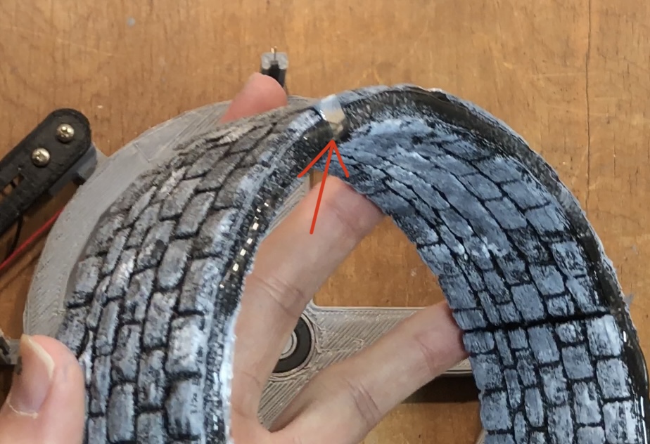
1/4" Magnet placement
With the magnet in place, we can now hot glue the wall and floor pieces to the rotating base, making the floor’s grid align with the corner piece when the room is opened. If you are following along with the video, this is when I flipped my entire project over and soldered some jumper wire onto the reed switches.
Testing the system's rotation with walls and floor attached
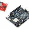
Now that the dungeon tiles are fully assembled, we need to attach our rotating room to a controller, which we will assemble out of a MicroMod Qwiic Carrier board (double) and a few Qwiic breakouts. First, insert an ESP32 MicroMod Processor into the carrier board and secure it in place with the tiny screw. Next, grab one of your three Qwiic Button breakouts and solder another reed switch into the two holes closest to the IC. This is important because the other two are not actually connected to the circuit, so if you try to use them, your switch’s input will not be detected. With the reed switch soldered in place, glue this breakout to the underside of one of the 3x3 tiles to act as a hidden trigger to open the rotating room.
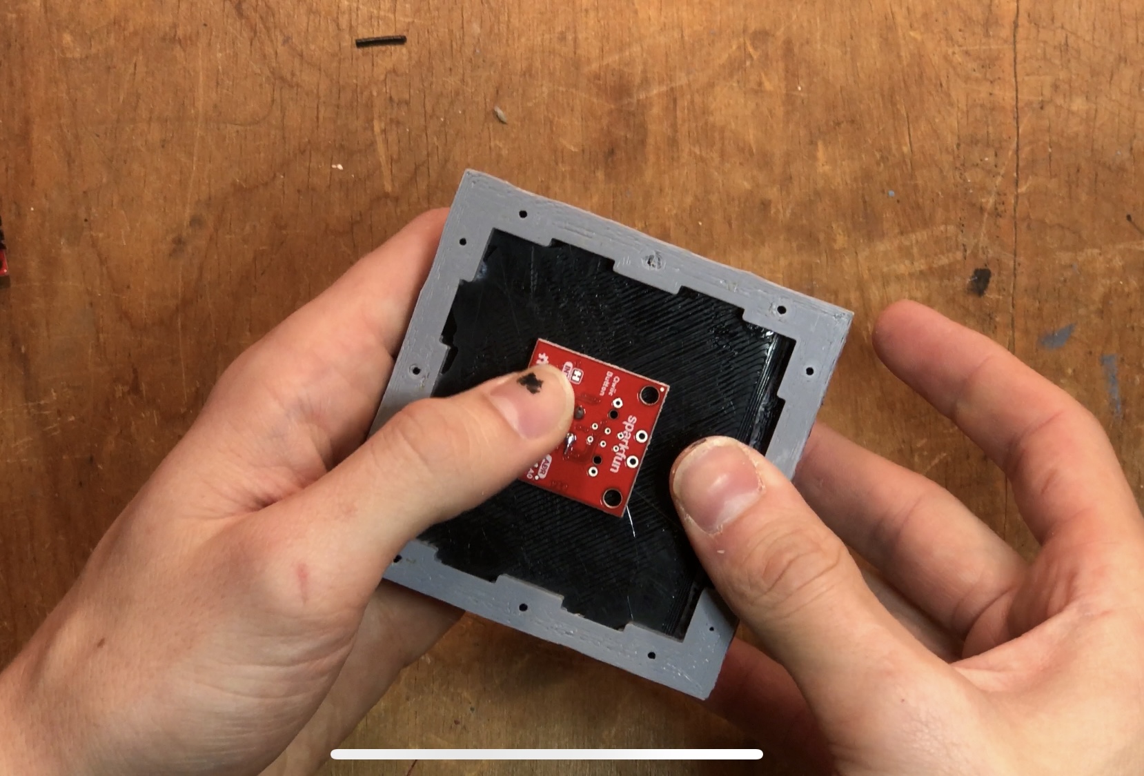
Hidden trigger tile assembly
Now, solder the jumper wires from the other two reed switches to a couple more unpopulated Qwiic Button Breakouts. Also, each breakout will need its own I2C address, which we can use the A0-A3 solderable jumpers to select. The reed switch that is activated when the room is opened should correspond to the Qwiic Button Breakout with the A0 jumper closed. The other reed switch (door closed indicator) should correspond to the breakout with the A1 jumper closed. As you will see in the Arduino sketch, this should mean that the hidden activation switch has the default I2C address, the door open switch has the I2C address 0x6E, and the door closed switch has the I2C address 0x6D.
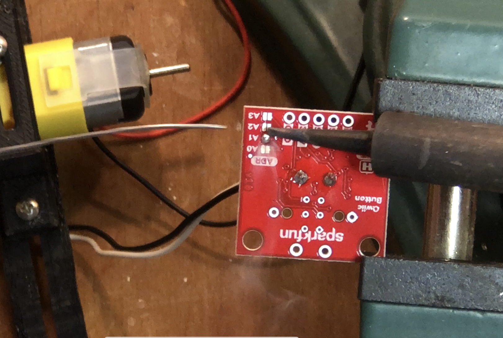
Using jumpers to select a unique I2C address
All our necessary Qwiic breakouts can now be attached to the mounting standoffs using the included 4-40 screws. I also added some nylon standoffs to the corners of my MicroMod carrier to give it some little legs to stand on. With the button breakouts wired up and attached, the final component of the circuit is the Qwiic Motor Driver. Secure it to the remaining open standoffs and connect the hobby motor to the screw terminals closest to the little OSHPark gear icon. The motor driver needs a power supply for the motors, so I soldered some wires to the 3.3v and GND pins on the carrier and inserted them into the corresponding VIN and GND screw terminals on the motor driver. Finally, the circuit can be completed by connecting all the Qwiic breakouts to the MicroMod carrier using flexible Qwiic cables.
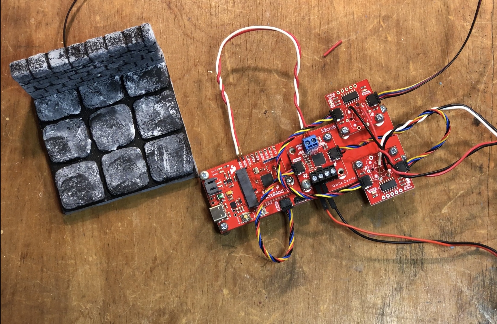
Fully assembled controller circuit, ready for programming!
Don’t forget to attach your trigger tile’s button breakout with a longer cable! If everything is assembled correctly, you can now upload the following Arduino sketch:
/******************************************************************************
  D&D rotating puzzle room demo
  Hardware shown here: https://www.sparkfun.com/news/3987
  Marcus Stevenson @ SparkFun Electronics
  Original Creation Date:November 1, 2021

  This code is Lemonadeware; if you see me (or any other SparkFun employee) at the
  local, and you've found our code helpful, please buy us a round!

  Distributed as-is; no warranty is given.
******************************************************************************/
#include <SparkFun_Qwiic_Button.h>
#include <Arduino.h>
#include <stdint.h>
#include "SCMD.h"
#include "SCMD_config.h" //Contains #defines for common SCMD register names and values
#include "Wire.h"
#include <WiFi.h>
#include <WiFiClient.h>
#include <WiFiAP.h>

const char *ssid = "dungeonMaster";
const char *password = "dungeonMasterPW";

WiFiServer server(80);

QwiicButton hiddenSwitch; //default i2c Addr.
QwiicButton doorOpen; // 0x6E
QwiicButton doorClosed; // 0x6D

SCMD myMotorDriver;

#define LEFT_MOTOR 0  //this project only uses one motor
#define RIGHT_MOTOR 1 //

void setup() {
  // put your setup code here, to run once:
  delay(50);
  Serial.begin(115200);
  Serial.println("Rotating D&D Room Demo");
  Wire.begin();

  WiFi.softAP(ssid, password);
  IPAddress myIP = WiFi.softAPIP();
  Serial.print("AP IP address: ");
  Serial.println(myIP);
  server.begin();

  Serial.println("Server started");

  myMotorDriver.settings.commInterface = I2C_MODE;
  myMotorDriver.settings.I2CAddress = 0x5D;
  myMotorDriver.begin();
  Serial.print("Waiting for enumeration...");
  while ( myMotorDriver.ready() == false );
  Serial.println("Done.");
  while ( myMotorDriver.busy() );
  myMotorDriver.enable();
  myMotorDriver.setDrive( LEFT_MOTOR, 0, 0); //Stop motor
  myMotorDriver.setDrive( RIGHT_MOTOR, 0, 0); //Stop motor
  Serial.println();

  if (hiddenSwitch.begin() == false) {
    Serial.println("Hidden trigger switch did not acknowledge! Freezing.");
    while (1);
  }
  Serial.println("Hidden trigger Switch acknowledged.");
  if (doorOpen.begin(0x6E) == false) {
    Serial.println("DoorOpen did not acknowledge! Freezing.");
    while (1);
  }
  Serial.println("DoorOpen acknowledged.");
  if (doorClosed.begin(0x6D) == false) {
    Serial.println("doorClosed did not acknowledge! Freezing.");
    while (1);
  }
  Serial.println("doorClosed acknowledged.");

  while(doorClosed.isPressed() == false){
    myMotorDriver.setDrive(LEFT_MOTOR, 0, 150);
  }
  //myMotorDriver.setDrive(LEFT_MOTOR, 0, 0,);


  myMotorDriver.setDrive(LEFT_MOTOR, 0, 0);
}

void loop() {
  // open door if hidden reed switch tile is activated
  if(hiddenSwitch.isPressed()==true){
    while(doorOpen.isPressed()==false){
      myMotorDriver.setDrive(LEFT_MOTOR, 1, 150);
    }
    myMotorDriver.setDrive(LEFT_MOTOR, 0, 0);
  }

  // server code for DM control from phone/tablet/computer
  WiFiClient client = server.available();   // listen for incoming clients

  if (client) {                             // if you get a client,
    Serial.println("New Client.");           // print a message out the serial port
    String currentLine = "";                // make a String to hold incoming data from the client
    while (client.connected()) {            // loop while the client's connected
      if (client.available()) {             // if there's bytes to read from the client,
        char c = client.read();             // read a byte, then
        Serial.write(c);                    // print it out the serial monitor
        if (c == '\n') {                    // if the byte is a newline character

          // if the current line is blank, you got two newline characters in a row.
          // that's the end of the client HTTP request, so send a response:
          if (currentLine.length() == 0) {
            // HTTP headers always start with a response code (e.g. HTTP/1.1 200 OK)
            // and a content-type so the client knows what's coming, then a blank line:
            client.println("HTTP/1.1 200 OK");
            client.println("Content-type:text/html");
            client.println();

            // the content of the HTTP response follows the header:
            client.print("Click <a href=\"/H\">here</a> to turn OPEN the rotating room.<br>");
            client.print("<br>");
            client.print("Click <a href=\"/L\">here</a> to turn CLOSE the rotating room.<br>");

            // The HTTP response ends with another blank line:
            client.println();
            // break out of the while loop:
            break;
          } else {    // if you got a newline, then clear currentLine:
            currentLine = "";
          }
        } else if (c != '\r') {  // if you got anything else but a carriage return character,
          currentLine += c;      // add it to the end of the currentLine
        }

        // Check to see if the client request was "GET /H" or "GET /L":
        if (currentLine.endsWith("GET /H")) {
          Serial.println("OPEN");
          while(doorOpen.isPressed()==false){
            myMotorDriver.setDrive(LEFT_MOTOR, 1, 200);
          }
          myMotorDriver.setDrive(LEFT_MOTOR, 0, 0);
        }
        if (currentLine.endsWith("GET /L")) {
          Serial.println("CLOSE");
          while(doorClosed.isPressed()==false){
            myMotorDriver.setDrive(LEFT_MOTOR, 0, 200);
          }
          myMotorDriver.setDrive(LEFT_MOTOR, 0, 0);
        }
      }
    }
    // close the connection:
    client.stop();
    Serial.println("Client Disconnected.");
  }

}
This simple sketch allows the player to open the rotating room as shown in the video by activating the hidden trigger tile with a magnet, but it also allows the Dungeon Master to control the room remotely from a smartphone or computer. To do this, you need to open up your device’s wifi settings and look for the “DungeonMaster” wifi network. This network is not actually connected to the wider internet but is simply a network being broadcast by the ESP32 processor. The password is “DungeonMasterPW,” but you can change that by modifying the Arduino sketch if desired. Once connected, open a browser window and type 192.168.4.1 into the address bar. This should bring you to the following simple page, allowing you to open and close the door remotely as you please!
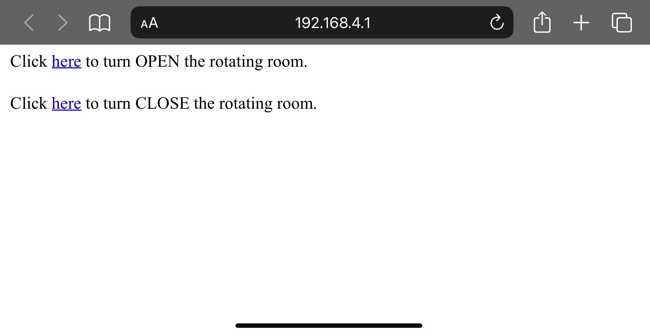
Simple remote interface
Thanks for reading! If you build this and use it in your campaign, let us know on social media!


Wow! Impressive. I think back when I was playing D&D about 40 years ago, working for the company that was "second source" for the Z80 microprocessor. (We were trying to get a 16 bit micro to market at the time.) WiFi and 3D printing were basically unheardof magic. ;-)