
Fidget Spinners: They're everywhere. Thousands upon thousands of plastic discs in every shape, size and color have been press-fit with skate bearings and piled high on every store shelf. Just like all fads, they'll surely fade from the mainstream before too long, but in the meantime every blogger, YouTuber and pop-culture commentator has something to say about the ubiquitous, gyroscopic toy. I've seen bladed fidget spinners, giant fidget spinners, even rocket-powered fidget spinners. Never one to let something this popular go by without investigating, I decided to build a fidget spinner contraption of my own: The Fidget Spinner Power Gauntlet!

The idea behind the Spinner Gauntlet is that if you embed magnets in a fidget spinner, you should be able to drive it like a brushless motor. All you need is a coil to alternately attract and repel the magnets as they pass by and some kind of sensor to tell the coil when to alternate. Let's tackle this one step at a time...
Jamming Magnets in a Spinner
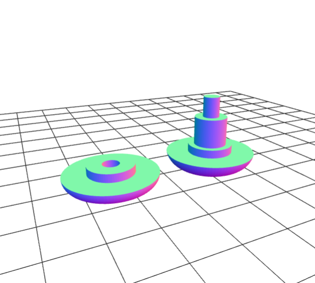
The first thing that I needed was a fidget spinner with magnets in it, which actually isn't unheard of in and of itself. But it's hard to determine exactly how the magnets are arranged in the various existing magnetic fidget spinners, so I decided to build my own. This way I could arrange the magnets however I needed, and I could also use very strong rare earth magnets, which I imagined would make my job easier. A few minutes in Fusion360 left me with a 3D model about like this:

The center hole is just barely large enough to press-fit an 8x22 bearing into, and the three square holes are a similarly tight fit for our 0.25" Neodymium magnets. Of course, I would also need to model the "button," the portion of the spinner that goes through the center bearing so you can easily hold onto it. I came up with a press-fit design that worked quite well for this fidget spinner as well as our National Donut Day spinner.
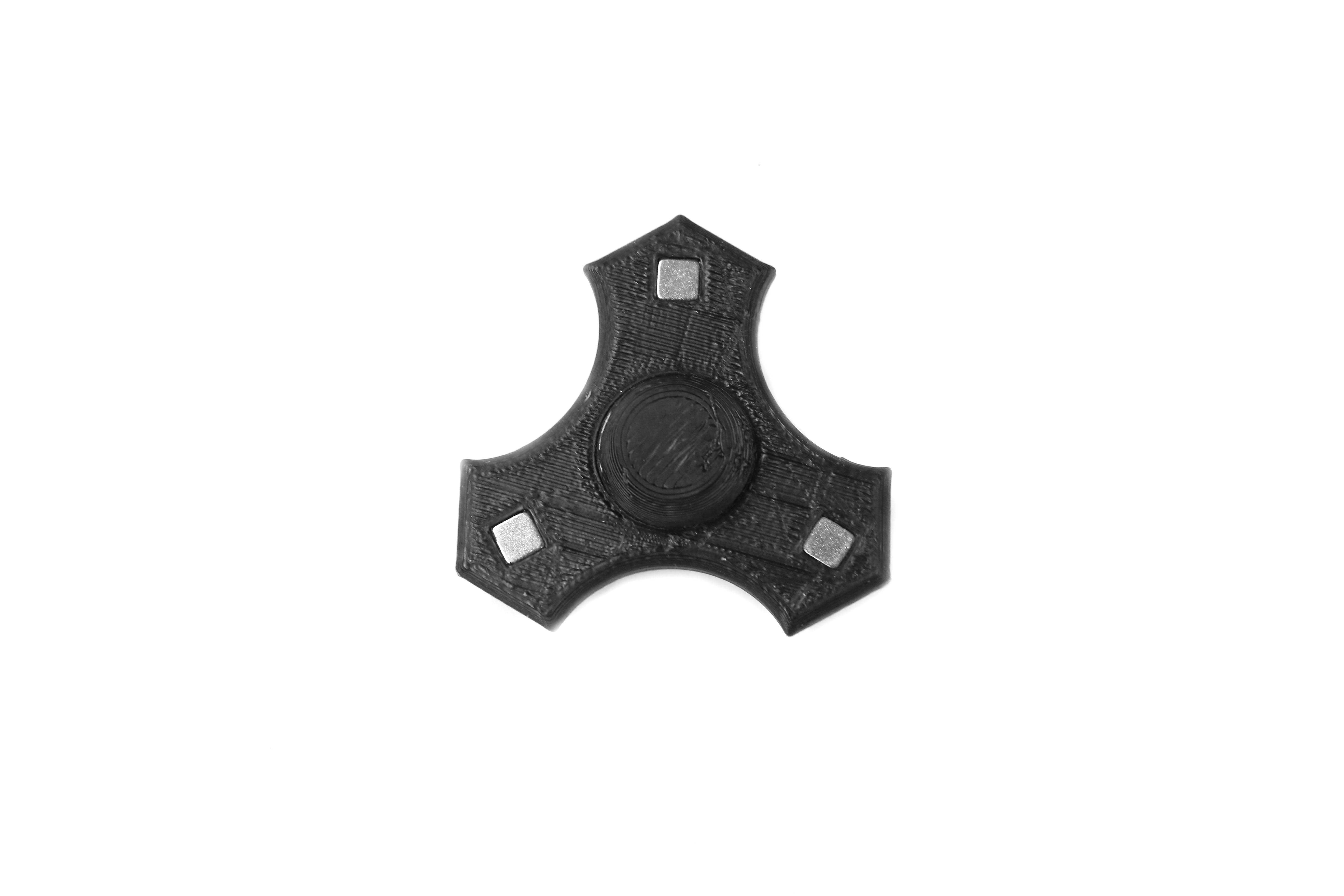
I imported the models into Cura and printed them on our Taz 6 3D Printer in black ABS. To my surprise, everything fit together with minimal sanding and trimming:
Driving a Coil
To build my electromagnet coil, I took a...less than scientific approach. I looked around the shop for a steel bolt that I could use as a core and then chucked it up in my cordless drill. I bookended the bolt with a few steel washers and proceeded to wrap as much 30-gauge magnet wire onto that thing as I could fit. Once I had nearly emptied a spool, I removed the washers, added some CA glue to keep the coil from coming apart and measured the resistance: just under 4 ohms. According to our old friend Ohm, this coil would be looking to draw about an amp and a half at 5 volts. Could be worse.
What I needed next was a method of driving this coil at full swing in both directions. Ideally, whatever I used to accomplish this task would be hardened somewhat against the potentially nightmarish effects of establishing and collapsing a magnetic field at better than 10Hz. This sounds like a job for a motor controller! While I briefly considered using the Ardumoto Shield, I decided ultimately that I wanted a little more safety margin on the current rating, so I stepped up to the Monster Moto Shield. I slapped one on top of a RedBoard and wrote a quick test sketch to alternate the coil once per second. It worked like a charm. But if I want to really get this spinner moving, I need that coil to speed up as the spinner speeds up...
Sensing the Spinner Position
The basic mechanic behind this whole project is as follows: The fidget spinner has three arms, each of which is equipped with a magnet that has, say, the north pole facing out. When the coil is driven such that its north pole is facing the fidget spinner, the two nearest arms are repelled and the spinner stops with the coil between two arms. If the coil is then "flipped," the magnetic field reverses and one of the arms is attracted to the coil, moving the spinner 60 degrees in some direction. Because we only have one coil, we can't necessarily guess which direction except if the spinner already has momentum in one direction. This flywheel effect keeps the spinner moving in the same direction as the poles of the coil alternate.
The trick with this system is that without some way of sensing the spinner's position, we can really only set our "motor" to one speed. Sure, we could adjust that speed manually, with a potentiometer or something, but the real goal here is to just spin this thing as fast as possible. Ideally, we would use a sensor to determine when the coil was between two arms and then swap the polarity until the coil was face-on with an arm. This is fairly easy to achieve by setting up a magnet sensor somewhere along the path of the fidget spinner; when the magnet sensor and the coil are at the proper angle from each other, they should set up the loop I described above. And this is exactly what I did. I originally intended to use a Hall Effect Sensor to detect the magnets as they passed because I was afraid that using a reed switch, though simpler, would be too slow. As a proof-of-concept, though, I grabbed a LilyPad Reed Switch and wired it up thinking, "If this is too slow or wears out, it's no big deal; I just want to see if this is going to work at all." And, of course, it worked like a charm. It turns out that reed switches have a very fast cycle time. To quote from "The Red Green Show": This is only temporary...unless it works!" And so the Hall Effect Sensor went out the window.
Almost a Shame to Use a Microcontroller
I can already hear some of you bemoaning the fact that I used a programmable controller at all in this project. No doubt, you could build a much faster circuit to do this using a few transistors, but I'm not optimizing this thing for manufacturing; I just want my toy to work! So I wrote a quick sketch for the RedBoard that couldn't be simpler: Drive channel 0 on the Monster Moto Shield forward at full-bore when the reed switch is closed. When the switch is open, drive channel 0 backward at full-bore. That's all there is to it. Any tuning that needs to be done can be achieved by physically changing the position of the coil and reed switch. Speaking of which, up until now the whole rig has been kind of haphazardly clipped into a set of helping hands on my workbench, but...
'What If It Were a Glove?'
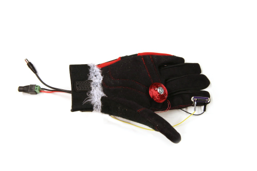
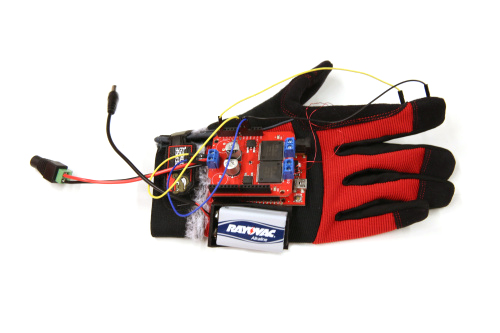
Finally, with the circuit assembled, it was time to mount everything in a useful way. I dug through the closet for a pair of old work gloves and started out by marking the position for the coil. I held the fidget spinner between my middle finger and thumb and found a spot in the palm of my hand where the coil would best interact with the magnets. Luckily, this glove is double-layered, so I simply embedded a steel nut between the two layers and screwed the coil into it. Next, I positioned the reed switch. The LilyPad Reed Switch was perfect for this project because it gave the fragile switch some mechanical support and made it easy for me to stitch onto the glove. I knew that tuning my reed switch position on the go would allow me a lot of control over the speed of the spinner, so I opted to put the reed switch on the end of my index finger. This way, I could move the switch in relation to the coil to get the best results. Finally, I found some space on the back of my hand for the RedBoard and Monster Moto Shield as well as a 9-volt battery clip:
'Yeah, but like...does it work?'
Oh yeah, it works:

Now What?
Well, now I'm gonna play with it, that's what! This was a fun project to throw together, and it provides endless amusement, even for those who are sick of the fidget spinner craze. It's also not a bad project for gaining a better understanding of how electric motors work. On top of everything, I'm basically a worse version of Iron Man now --- and that's the best I could have asked for.

What Hath Man Wrought


So.. Instead of the transistors, you used a microcontroller... That's fine, but now that it's there.. USE IT! I wanna know how fast this thing goes.. How about an LCD with current and max RPMs? Also, a video of it running instead of just the GIF?
Seeing this thing get going quickly is a must! Lube up that center bearing, crank up the juice and go! On a serious note, this is a cool little project. No actual real use for it, but it sure is fun to watch. It is amazing how these spinners have taken over so quickly. But they came in quick, they will disappear quick.
A fidget spinner as the "armature" of a brushless motor... genius. I'm kicking myself for not thinking of this :)