
Eagle has been our go-to CAD program for quite a few years now, and while it's relatively easy to learn and use, I've always struggled to learn the keyboard shortcuts. Some of the other engineers here use the shortcuts quite regularly, and have created their own shortcut keys using the modifier keys (CTRL+ and ALT+), but I've always found it faster to just move my mouse over and use the left control menu.
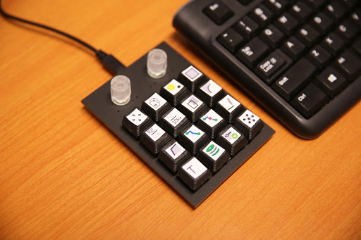
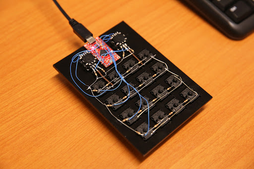
That changed this week, when I decided to make a Cherry MX keyboard to handle shortcut keys. The keyboard has 16 Cherry MX switches and two rotary encoders. The keyboard uses a Pro Micro to read the switches and encoders, and because the Pro Micro has native USB, we can use it to tell the computer that it is a USB keyboard device. The project only requires two libraries: the HID library, which is based off of Arduino's mouse and keyboard libraries, and the Teensy encoder library.
How Does It Work?
Let's start off by looking at the schematic:
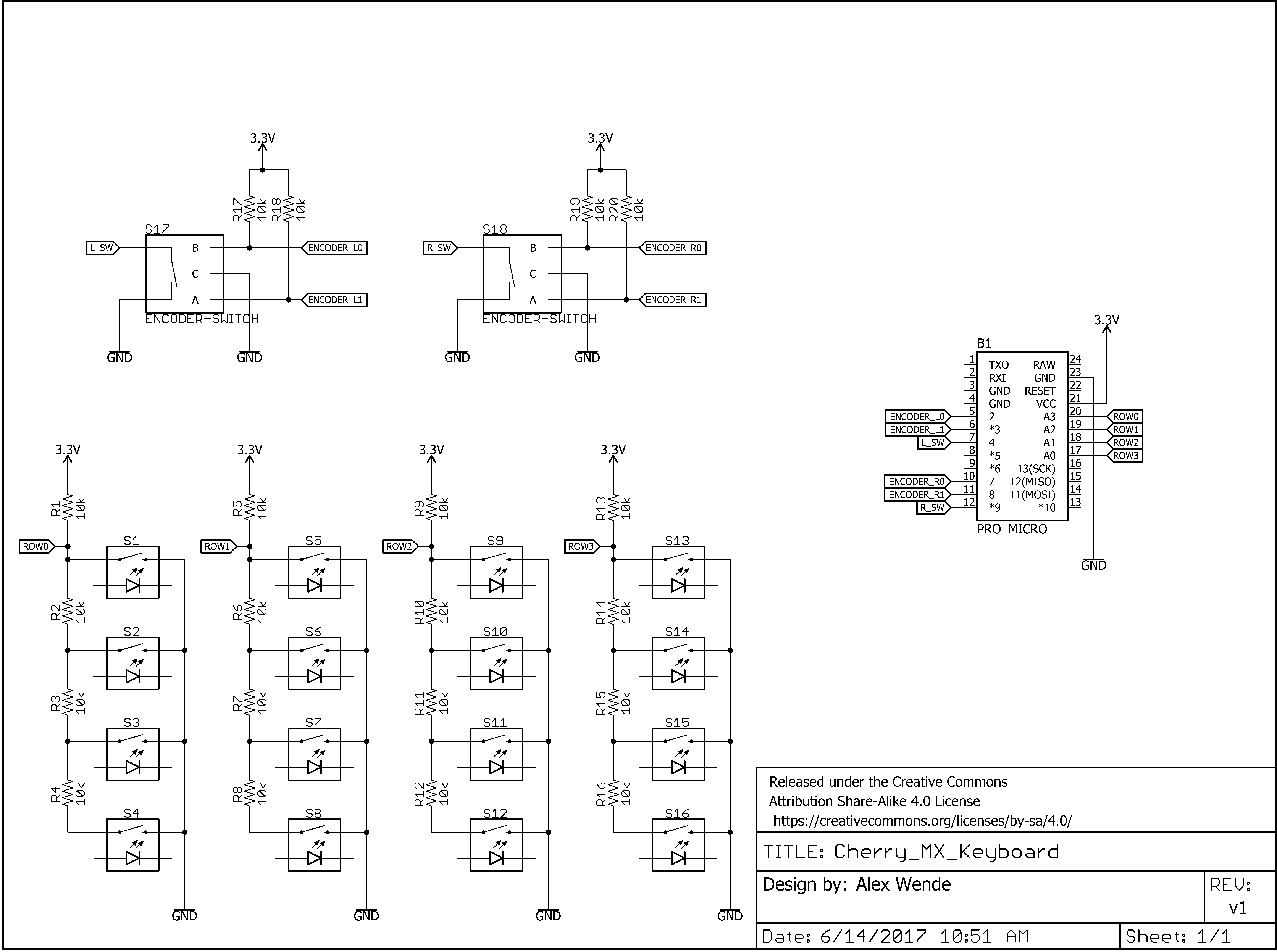
The Pro Micro doesn't have enough IO pins to handle 16 switches and two encoders, so I first had to figure out a way to multiplex the switches. One of the easiest (and cheapest) ways I've found to do this is to create a voltage divider. By having each of the normally open switches connected to the voltage divider and ground, I'm able to use an analog pin to read the voltage and decide which switch was pressed in the row.
One of the problems I ran into while working with Arduino's keyboard library was the lack of support with multimedia control. The multimedia keys control things like play/pause, next/previous and volume. Thankfully someone already created a library to expand Arduino's library to include the media controls, which I attached to the left encoder using the functions Consumer.write(MEDIA_VOL_UP), Consumer.write(MEDIA_VOL_DOWN), and Consumer.write(MEDIA_VOLUME_MUTE).
Sending keyboard commands is really easy to do too. Sending a string of text is done the same as printing a message on the serial window, except instead of using the Serial class, you change the class to Keyboard. Because Eagle has a command line interface, I was able to print the commands directly to the command line. In other programs where you only have access to shortcut keys, you can still use modifier keys (i.e., Ctrl+ and Alt+) by using Keyboard.press() and Keyboard.release() or Keyboard.releaseAll().
How Well Does It Work?
Better than I thought, actually! When I designed the schematic, I primarily used the extra keyboard, and aside from having to look down to see what key I needed, I got used to it pretty easily and made the schematic design go by pretty quickly. For a quick demonstration, check out the video below.
Want to make one yourself? I've put all of my designs on GitHub, along with links to all the resources I used. The only request I have is that you share some photos and let me know what you use it for, or what improvements you make. A link to the repo, along with a wishlist, is provided below.


Nice project!
And BIG THANKS for including a png of the schematic in your github! For those of us not using Eagle, it is much more convenient.
This looks to have real possibilities for PC-based games. Very cool.
How about a remake of Atari Star Raiders
Anyone considering a project like this should probably also look into arcade control boards, especially if you're not so comfortable with programming or the Arduino IDE (or you're in a hurry). Ultimarc has some excellent offerings, which I have used. A windows app lets you map pins to keyboard keys, and write to the firmware on the board. The board then acts as a USB keyboard. My project used arcade buttons and an ATTiny to drive a simple capacitive touch sensor and write to the pins on the Ultimarc board. It was a foot powered mouse for someone that couldn't use their arms.
I did a similar project myself. I used a cheap usb num pad and replaced the guts of it with a 4 port usb hub, and a pro micro. when the num lock is on then it functions just as you would expect, but when the num lock is off, then it turns into a short cut keys that run any combination of multiple key presses. And because I used a usb hub, I also soldered in a small usb micro sd card reader and I keep the firmware on a 16gb sd card so that I can change it and download it to the pro micro any time I want to.
One thing that I did struggle to do was to create custom images to put on the key caps that would both fit and also not fade/degrade over time. How did you create and attache the images to the key caps.
I bought a pack of sticker paper on Amazon. To make the icons, I just changed the icon size to 36 and did a screen capture and printed out the entire menu. The key caps need an acetone bath to smooth out the layers, because a couple have already started to peel up.
I'm planning on printing out more icons with regular paper and using contact cement for better adhesion. I'd like to also protect the images from fading as well by using a clear epoxy over the top or maybe just a couple coats of clear spray paint.
I just had an interesting thought. I don't have an ABS printed part on hand to try this out. How about clear nail polish as a sealing/smoothing coating? It is acetone based so should chemically bond to the ABS. Even if it doesn't remove the appearance of layers, it should fill the valleys (particularly if applied in several coats, maybe some sanding between coats like building up varnish layers on wood) between the layers to provide a smooth surface for the stickers. And then a couple coats on top to seal the label inside the nail polish.
If it works, all the credit I require is "some dude on the internet hypothesized about this..." (i.e. be humble and don't take credit for ideas that aren't your own, but I doubt this is a unique idea so I don't need personal credit.)
The voltage divider is a cool trick! I'll have to remember that one.
When you have enough digital pins available for each row and column (4+4, so 8 in this case), I found it really easy to create keypads that work with the Arduino Keypad library for detecting key presses.
Actually, to fully matrix all the switches he would need 9 pins (the encoder switches would be either on an additional row or column). He could also have used the voltage divider trick for those two switches. There are enough extra analog input pins available on the pro-micro for this. See this pin-out image.
But, yeah. With lots of matrix keyboard examples out there, this is a good example of another way to skin this particular cat.