Enginursday: Troubleshooting a Simple Problem
Sometimes troubleshooting requires you to think both literally and figuratively "outside the box."

Hearing about frigid temperatures in the Northeast recently got me thinking about how I used to have to troubleshoot static problems in a previous job when the weather was consistently cold and dry. Most of the time the problems were quick to identify, and easy to fix. But there was one time where it was a simple problem to fix, but hard to spot.
Backstory
My first job out of college was as a Junior Engineer for a large printer manufacturing company. The department I was in focused on the specialized sensors used in the printers. The sensors ranged in complexity from simple off-the-shelf temperature and humidity sensors, to custom imaging modules that were built in-house (similar to the imaging sensor used in a scanner). The imaging module we were investigating is similar to a competing imaging array made by Mitsubishi, shown below.

Contact Image Sensor courtesy of Mitsubishi Electric
As a Junior Engineer, I mostly worked with a Principle Scientist who had been with the company for 30+ years. His background was the same as mine (B.S. in Electrical Engineering), but he specialized in electrostatics (static electricity). Most of the year we focused on the Xerography of the printers --- moving toner from the cartridge or bottle to the paper using static electricity. But every year on the coldest, and driest, days of winter, we would get calls about static causing problems on a machine. Most of the time the problem could be fixed by installing an antistatic brush in the paper path before where the problem was noticed, and it would go away.
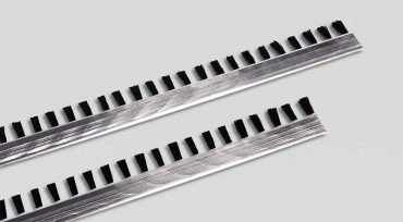
Passive static eliminator image courtesy of KOTI
One time, though, we were left scratching our heads for a couple of days. The printer we were dealing with wasn't a personal desktop printer, but an industrial printer that is almost 7ft tall, and a little under 20ft long --- printing on a continuous sheet of paper up to 500ft per minute. The paper is unrolled on one side, printed, flipped and printed on a second printer before being rolled back up, or folded and cut to size. Thankfully, to get from the front of the machine to the back you didn't need to walk all the way around the printers; the box that flipped the paper was made of steel and allowed you to safely step over the paper to the other side of the machine.

(Not at all to scale, but you get the idea)
The Problem
The reason we were called in was that, after a period of time, the imaging sensor that my group was responsible for would reset itself and cause the machine to stop. We stopped by and asked the operator of the machine to describe the problem and try to replicate it. We were quickly able to figure out that the problem was static-related and told the machine's operator to install the antistatic brushes in the paper path both before the sensor as well as after, and the problem should go away. Spoiler: it didn't.
The next day were back at the machine making sure the brushes were installed correctly (which, of course, they were) and did even more head scratching. We started to look at the second machine to see if somehow the static was building up on that machine and getting to the first. But before we ventured too far down that rabbit hole, we wanted to check the steel box that flipped that paper over, just to do our due diligence and eliminate it as a factor. We noticed two things odd with the box. First, there was an ethernet cable connected to the problematic machine on one end and tossed under the box on the other. The second problem was that the steel box should have had a grounding wire on it to prevent static buildup on the paper as it passed from one machine to the other, but it didn't.
As we moved onto the second machine, we asked if the cable needed to be connected to the first machine, and to remove the tripping hazard if it didn't. For the sake of thoroughness, we asked to install a grounding kit to the box to avoid potential future static problems on the second machine. We continued with our testing but couldn't replicate the problem anymore. As it turns out, the problem was that, as the paper moved on the rollers in the box, it was acting like a Van de Graaff generator until it arced over to the ethernet cable. The static charge was large enough that it interfered with the image module, causing a fault, which was recovered by a reset of the module. In a more humid environment any other time of the year, the problem never would have presented itself. But as it was, the problem managed to take multiple engineers multiple days to figure out.
In a complex system like a printer, sometimes it's the simplest of reasons that cause the largest headaches. What problems have you had to troubleshoot that took you longer than you'd like to admit to figure out? Let us know in the comments!


I was called in as a consultant to diagnose random resets of a custom engine control unit for a diesel to natural gas conversion kit on a commercial generator. The genset was housed in a storage container like you see on the back of a semi truck. It had a large diesel motor and our system intercepted the existing control module signals to/from the engine sensors and control systems. When the conditions were acceptable, our system would force their control module to minimize the amount of diesel being injected while operating our own natural gas solenoids. The diesel at that point was basically only used to initiate a pilot ignition while most of the combustion was natural gas. The engineers were experiencing difficult-to-reproduce failures which appeared to be ECU resets (on our control module). One failure was apparently quite exciting as it caused a large backfire which blew the doors of the storage container open. I verified all of the wiring and signals looked correct and we were about ready to go into the firmware looking for a culprit when somebody asked if the issue could be caused by the fact that the microcontroller was in a socket instead of soldered down (this was an early prototype unit). Once we moved to a soldered-down version of the ECU the problem was solved. The vibrations from the engine must have been enough to cause the chip to lose electrical contact from time to time. Later on we also found another issue where wires to a solenoid were run in a wiring harness next to sensitive sensor outputs. The solenoid was being driven by a MOSFET switching a +15VDC PWM signal, which made for some nice noise glitches. When the microcontroller happened to sample the ADC inputs at just the wrong moment, bad things happened. We solved the problem with some series resistance and ferrite beads. Sharp edges bad, yo.
I work as a test engineer, designing test equipment for stress testing (environment chambers). We use an embedded control board (test controller) which controls power cycling the units under test (UUT), as well as applying stimulus and reading outputs from the UUTs. A PC is used to monitor test status by polling up to 8 of these test controllers getting test results, errors messages, etc. This path is a multi-drop RS-485, but for lab development/debug there is also an RS-232 port to connect a PC to one test controller. When we rolled out this new design we started seeing random test failures or glitches during the typical 3 hour run we use for testing. Eventually I noticed that the glitch would occur when the PC was polling the test controller, which occurs every 9 seconds. The connection between the test controller and the fixture in the chamber is 5 meters cables, with 75 wires in each cable. All the connections on the test controller by default are connected to these cables, which by mistake included the RS-232 signals. So each time the test controller replied to a poll, it transmitted both on RS-232 and RS-485, so we had a +/-15 volt wave form on a nice 5m antenna causing these glitches. Quick fix was to cut the traces going to the cable connector, until we rolled out a new artwork for the test controller.
I am a test engineer also. This quote from one of my coworkers sums up my job so well some days " Welcome to Test. Finding product bugs and design problems are just some of the many services we provide to our suppliers as well as our customers "
I work for a competitor of yours in the printing business on exactly the same type of printing system (and hint: I'm within a strong driver's distance from Sparkfun :) , and I have encountered and had to deal with this exact same problem. I loved reading this story, thank you.
I thought you were going to say that it faulted when someone walked across the metal box that did the flipping.
Once I was sent out on a service call for a large steel slitting machine, similar to the paper machine you described above. It would unroll thin gauge steel, slit it into strips of various widths, then roll it back up. So the layout of a typical machine is that there is a station that the roll is placed on to be unwound. It has a brake to put a little back pressure on the steel. Then there is the slitting arbors, they are driven with a large industrial motor. The ones I worked on were typically DC motors. The steel then went down into a looping pit, then through a tension station, then on the the rewind, (also DC).The looping pit is required because believe it or not, coils of thin steel that are rolled up do not have the same thickness all the way across the roll. Before it is slit into strips, this isn't a problem. Once they are slit, the small differences in thickness cause the rolls that are thicker to make a larger diameter roll, causing those to get tight, and the thinner ones to get loose. The looping pit takes up the difference in the diameter of the rewound rolls. But, if the coil is very thin and long, the loops can get so different in lengths that the ones are tight, and the others are scraping the floor of the pit. If that happens, they have to stop, cut some off to even them up, and then go again. Google "Steel Slitter" for pictures.
This particular machine had an extra section. It was called an infeed. It was powered, and it fed the material into a loop ahead of the slitter head. I think this was for thin material. Since it is before the slitter head, the steel is all still in one piece. There was an ultrasonic sensor aimed down at this primary pit to adjust the speed of the infeed section to keep a stable loop depth. Ultrasonics don't work on the loop after the slitter head, too many strips to watch.
I was told the Ultrasonic sensor was messed up. I was also told I was the third technician to come and try to fix it. While the line was running, this loop would randomly come up to tightline, which leaves a mark on the material when the slitter heads slip on the steel. So I set myself to watch the machine and see it happen.
I noticed that when the operator saw that the loop after the slitter head got too deep, he would adjust the speed of the slitter down so that the slit set of loops could get shallower. Slowing down the slitter makes the primary loop get deeper, so the ultrasonic sensor would see the deeper loop, and slow down the infeed to make that primary loop get a little shallower. At that point I noticed that an extra loop would form in the material between the unwinder and the infeed. Mind you, the unwinder has a brake to keep tension between it and the infeed. This caused the unwind roll to actually stop, because it was no longer being pulled. Then the primary loop would get too shallow, and the ultrasonic sensor would command the infeed to speed up. So it sped up, taking up the slack that it had created in the extra unintentional loop between the uncoiler and the infeed. When it got tight again, it would "snap", as the tons of steel sitting on the uncoiler has a lot of inertia, and does not start rolling instantly. When it "snapped" however, the infeed would lose grip on the steel, (it's oily). Since it lost grip, the loop primary loop would continue to get shallower, and the ultrasonic would command more speed from the infeed to try and get the loop deeper. But after traction was lost, it was all over. It was like car tires on ice. The rolls would just start slipping faster and faster, until the primary loop tightlined and marked that material.
So the ultrasonic sensor was fine, it was the fact that there was not enough brake tension on the unwinder to prevent it from coasting forward when the line slowed down. Easy fix. I showed the operator and the maintenance personnel the problem, and told them to crank up the brake on the unwinder, (a normal operator control). I was told they couldn't do that because then the infeed would not be able to pull the material off the unwinder. It seemed that the rubber rolls on the infeed were worn out, and did not have enough traction.
I then said, "My work is done, you either need new rolls on the infeed, or get them resurfaced".
Two other technicians had each spent an entire day there, on separate occasions, attempting to speed match the infeed and calibrate the ultrasonic sensor. They even turned up the amount of influence the ultrasonic sensor had on the infeed speed, effectively making the problem worse.
Moral of the story? Sometimes you just have to sit back and look at the problem from the wider perspective to see the real problem.
This sounds somewhat similar to the 3M making a force field.
Years ago I worked for a subcontractor that supported the South Pole Station. Temperature inside the station was kept to around 60 degrees F, but the relative humidity is typically < 1% due to the outside temperatures. One of the biggest failure issues they had that wasn't caused by the cold was the cooling fans for the various IT equipment. They would typically see about 10-20 failures a year of power supplies where the brushless cooling fan would fail due to the low humidity and static discharge. No good preventative fixes, just developed a process of having 20-some spares on hand for the year.
Hey, I've been to the South Pole Station. I worked on the Ice Cube project. This project has a server farm running data collection on the array (called the Ice Cube Counting House). I wasn't directly involved with the computers, but from my couple tours of the counting house I know that they take ESD issues seriously. No one was allowed in the server room without at minimum an ESD dissipative coat/smock. And that was to just walk around and look at the equipment. Even more ESD reduction measures were required to actually touch the computers. But... that room was always warm.
I hope your work with that subcontractor gave you the opportunity to go down to the ice at least once.
Total power supply failure caused by unplugged power cord hiding in a snakepit of identical cords, some plugged in, some not.