Tube Amps in the Age of Bluetooth Speakers
The convenience of advancing tech can kill a good nostalgia project...but it's not quite dead...

Full disclosure: this is part confession, part rant and part technical breakdown of obsolete tech. And it’s probably going to be long. You were warned…
The Story So Far…
First, some history. When I was growing up, we had a Grundig Majestic (links to which are sketchy and few) console radio/turntable that I sorta unofficially inherited for my room. And I fell in love with this thing. It had the best sound of anything I was hearing, and it sounded distinctly different. And that’s because it used tubes as the active elements.
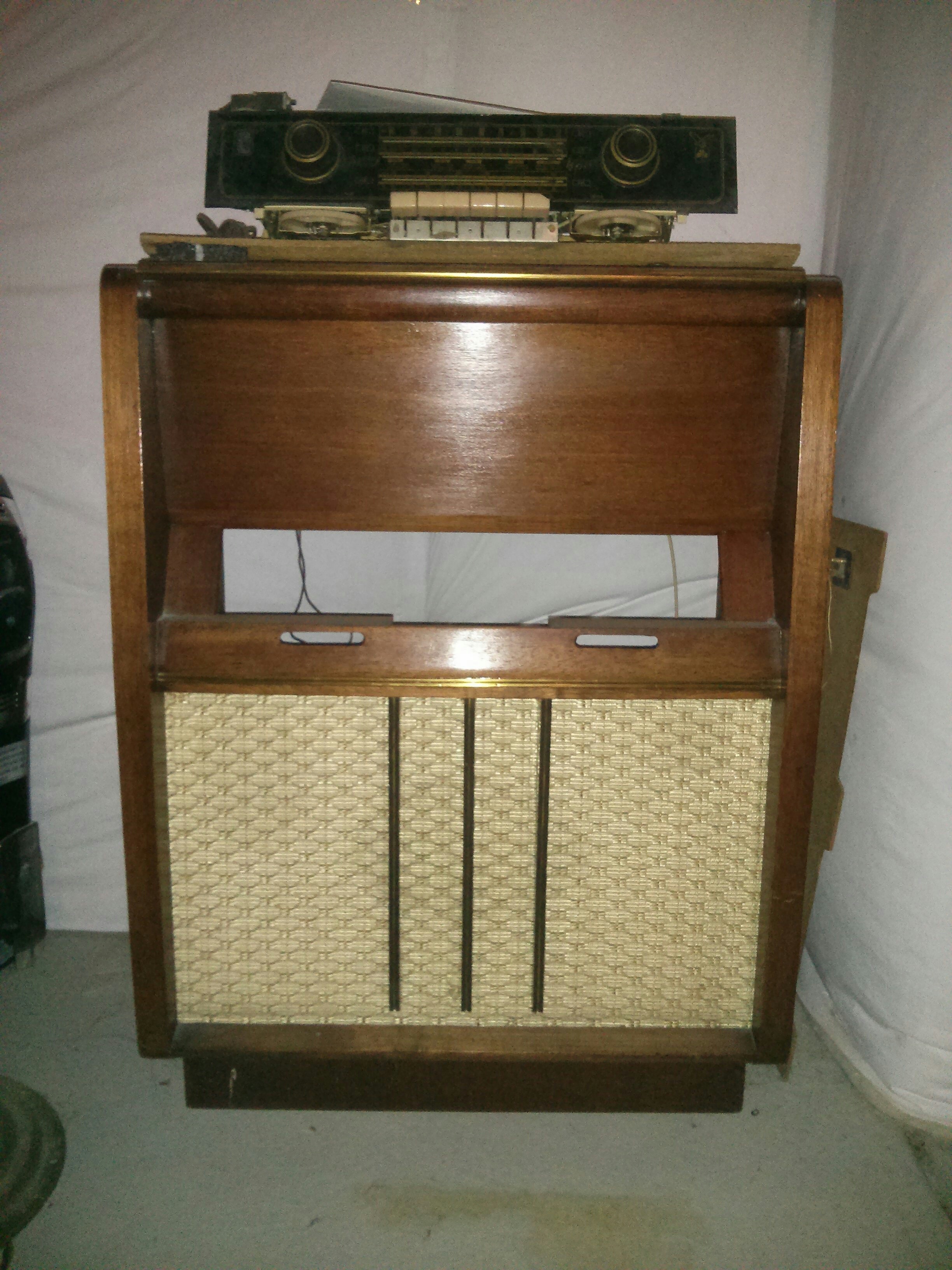
My baby's seen better days, but she's all there.
Fast-forward to about 10 years ago. I thought it would be a fun side gig to design and produce tube amps for money. So I created my first design, just to get my feet wet, with an EL84 ultra linear output stage, 6922 concertina and a 12AX7 input/bass/treble section. It was a great success for me, and I dressed that sucker up with LEDs and a bunch of other features. And once that was done, I started on the next design with an EL34 output section, and I got some (6) output transformers custom-built by a gentleman from the Seattle area who was wise in the ways of such things.
Then my partner and I went to the Rocky Mountain Audio Fest. I was really happy with my work thus far, but I needed to immerse myself more in the ways of the competition. But in attending, I came face-to-face with the sort of bald-faced lying that happens in the audiophile gear genre --- $100K+ for a pair of speakers. Little sawhorses propping up a power cable a few inches off the floor because, you know, we don’t want to get any floor-induced parasitics into the audio. All justified with lines like, “Achieve the truest representation of what the artist intended.” Are you kidding me? Listen, I’ve been on the other side of this equation before, and you’re giving this imaginary “artist” person way too much credit. And these sawhorses…do you know what happens to your precious line voltage on the other side of that outlet? But oh, the clarity! Right. Miles and miles of unshielded cable and substations, and you think you've improved your sound by suspending the power cable 6 inches above your floor for the 4 feet between the wall outlet and your gear? Pardon me for saying, but I think that if you put any stock in that tripe, you probably deserve to pay $4K for RCA patch cables.
But whatever, right? People have to have their hobbies, and I’ve spent tons of dough on mine. It so happens that for this hobby, the exorbitant prices to participate are less about the sound of the gear than the identity it buys the purchaser. That’s fine, and not entirely uncommon. But I’m not going to be the one to tell you stories to extract as much of your money as possible. I just can’t be that guy. Bad businessman Pete, I guess. The quandary brought the project to a halt.
Then some life happened. Kids and all that goes with them, and various other extreme draws on my time and energy. But about five-ish years ago, I decided that I couldn’t let those output transformers I bought sit on the shelf forever. I had to finish the design and build the two EL34 monoblocks I had planned years before. It’s been a long haul, but this past Xmas I was determined to finish these two amps. Why has it taken so long? Lots of reasons, top of the list being the kids. And it doesn’t help that I’ve got the attention span of a gnat. But also, Bluetooth® speakers are just so convenient! And I also started at some point to buy digital music. Phone/tablet/computer + Bluetooth speaker + MP3s = a really easy and portable soundtrack to your life. Does that combination sound as good as a tube amp and a pair of nice B&W speakers? It sure does NOT. But it’s just convenient enough to keep my amps terminally on the back burner. Until this last Xmas.
Now, I have to admit that I didn’t technically meet the challenge. I did not finish both amps. But I did effectively finish one --- all the bugs worked out, passing audio and sounding really, really good. The second one should just be turning the crank. Heh. Yeah.
The Design
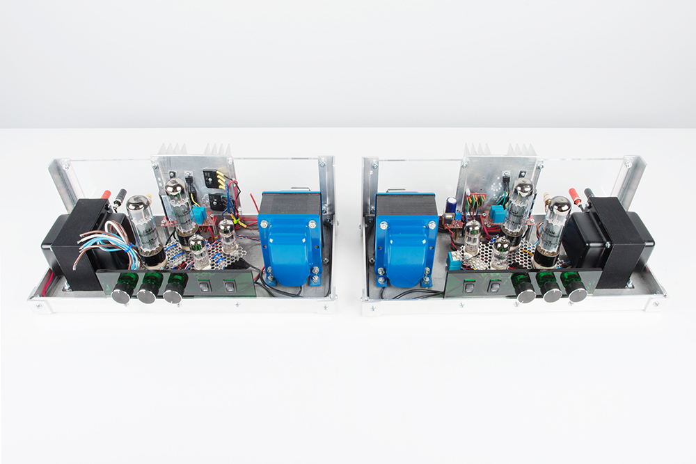
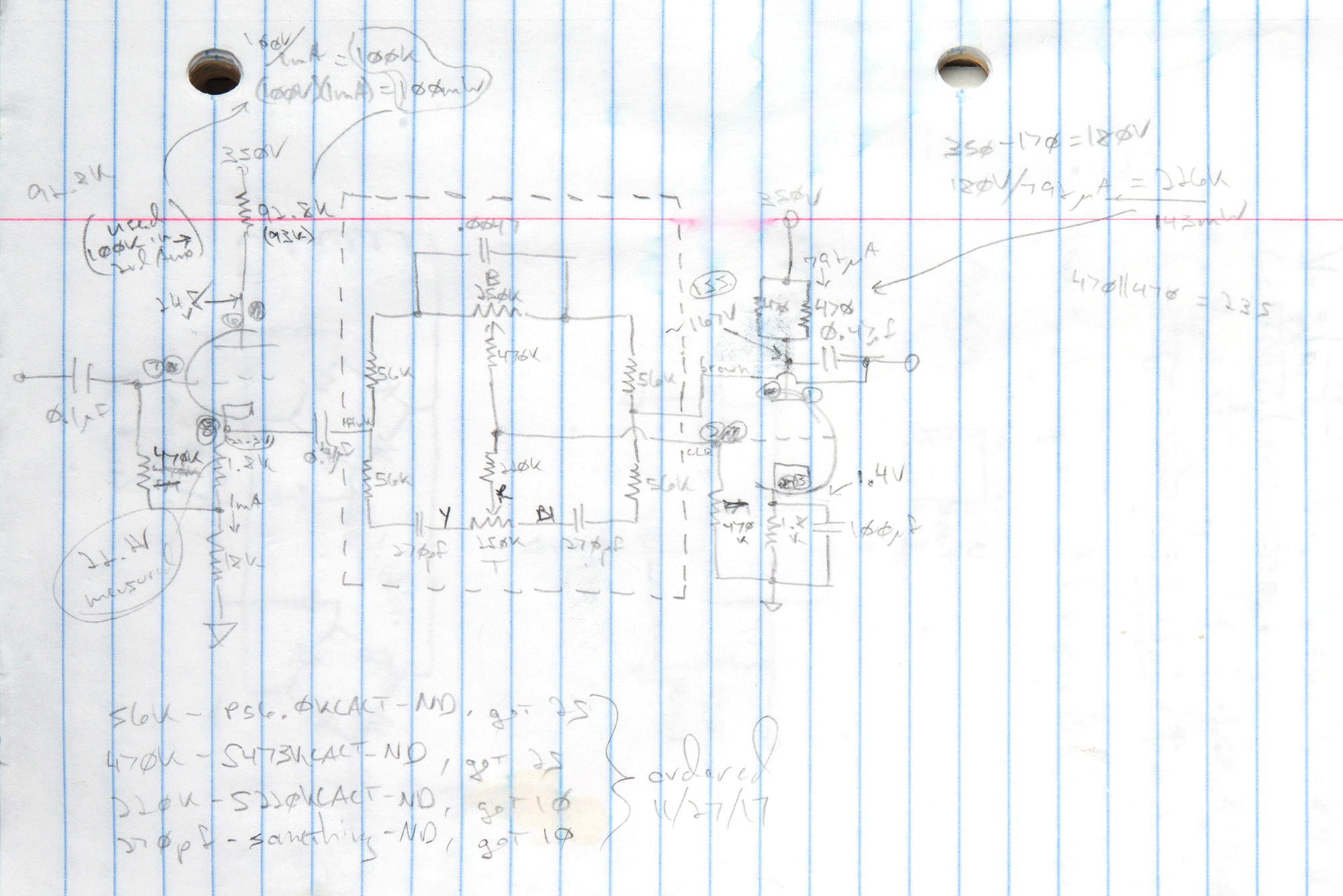
But enough of that. What are we actually looking at? It’s largely the monoblock design I talked about above, and the two of them are book-ended. 12AX7 input/bass/treble section, 6922 concertina and an EL34 ultra-linear output section. The HT supply is regulated 350V, and half of the LT supply is DC-regulated 6.3V. Schematics graciously provided by my notebook. This is all point-to-point wiring, so an electronic form of the schematics doesn’t currently exist. They may be a little sketchy for the casual observer, so lemme know of you’ve got questions.
I’ll start with the LT supply (low voltage, high current for heaters) because it’s the section that’s given me the most grief to get right. First, keeping 60Hz out of the audio is paramount, which is why I went for regulated supplies. But with 6.3VAC RMS (8.9V peak) out of its low voltage winds, the power transformer I chose didn’t give me much headroom to pull that off for the 3.6 amps the tubes were going to need for their heaters. I swear I did all these calculations back in the day that would allow this purchase…but it appeared I had shortcut myself into a corner. To illustrate, 8.9V peak - 2 diode drops (1.2V) - regulator dropout (negotiable, but call it a very generous 1V) - 6.3V output = 0.4V allowable ripple voltage. More than that and the regulator fails to regulate. I’ll spare you the equation, but that takes many tens of thousands of uF to accommodate. And while that’s a possible solution, it’s hardly an elegant one. So after many iterations, I ended up with this circuit.
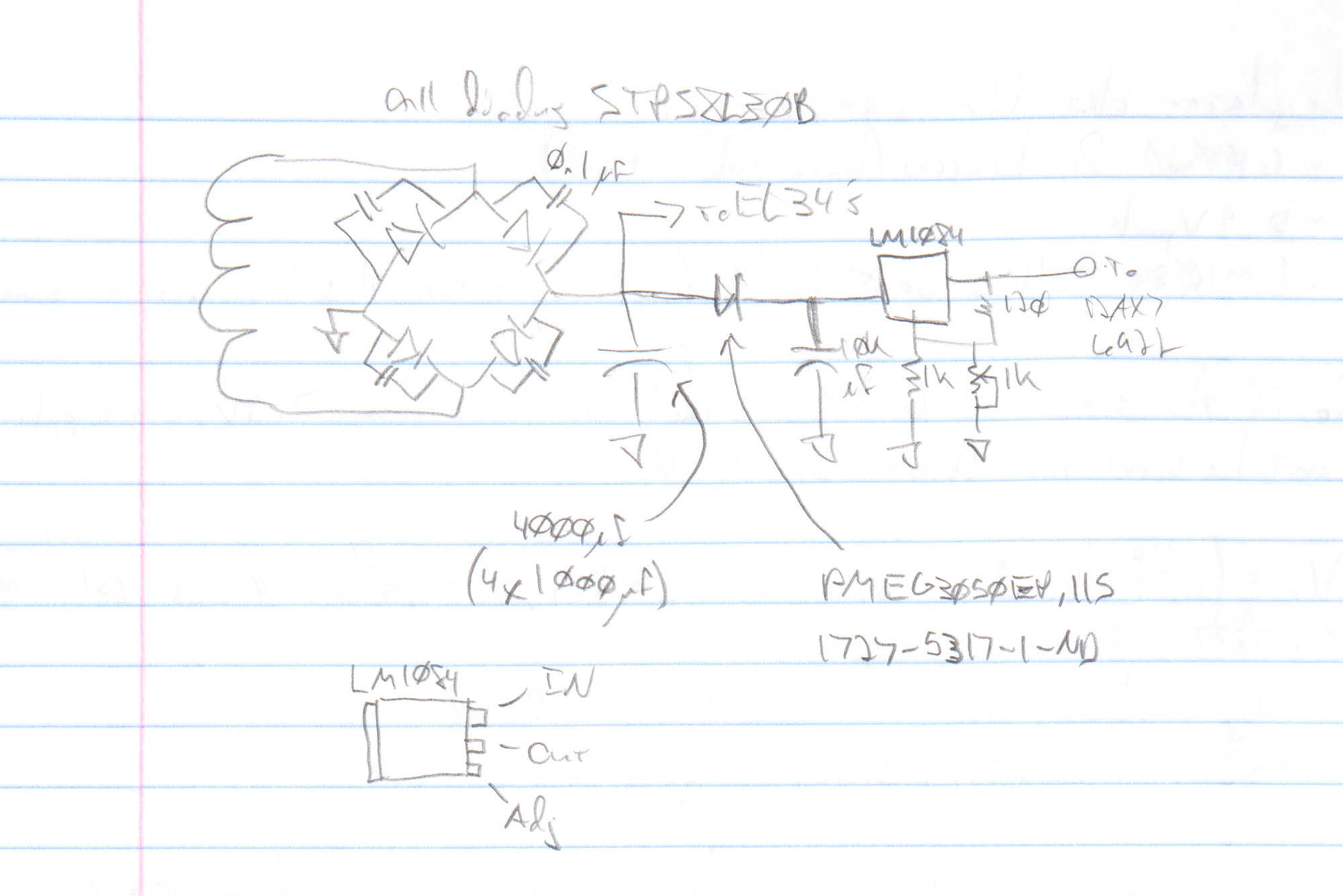
As it turns out, I can effectively ignore 60Hz noise coming from the EL34 heaters because of the push-pull output topology: since the output transformer translates changes in current and the heaters are impacted in the same way by the same noise (as in common mode), any current fluctuations will be equal and opposing, and 60Hz at the output will not result. So I can basically ignore 3 amps for regulating, but I still have to separate the sections with a Schottky diode so that my filter cap for the 12AX7 and 6922 sections doesn’t go to feeding the EL34s. For those, I use just enough capacitance to get the average voltage into a workable range (4,000uF and about 6.4V). For the remaining 600mA, I use a low dropout regulator (LM1084) good to 5 amps, which I’ve made adjustable with a 10-turn trimpot. And using a mere 10,000uF, I can dial out the last of the ripple giving me about 6.1V. The rectifier that feeds both of these sections is also comprised of Schottky diodes good to 8A continuous and 0.2V forward drop (STPS8L30).
Next is the HT supply, which is regulated 350V at 200mA. I had some experience with this topology from my first design, so this one really didn’t present me with any surprises.
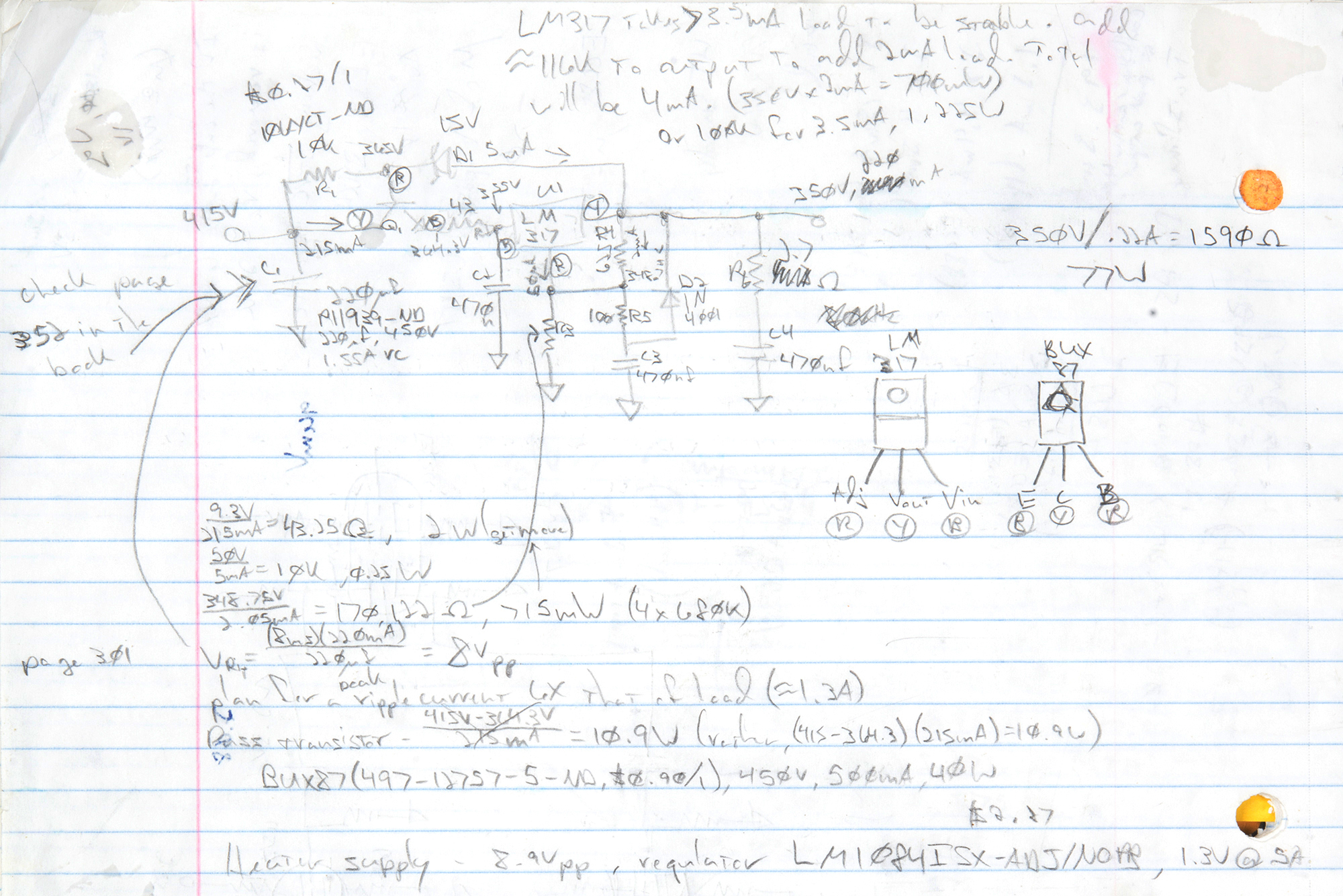
I lifted this from a Morgan Jones book, but I think it’s an LT reference design…somebody’s reference design, anyway. I’ll leave it as an exercise for the reader to suss its operation. There’s still a bunch of amp to get to, and this bit isn’t all that interesting. But yes, that's an LM317 in the middle.
Now let’s talk about audio. My approach here was a little different from what might be expected, for better or worse. I consider it experimental, but I’m really happy with the results so far. EL34s are relatively high power (from my perspective), but I honestly don’t need all that much power. So I’ve traded gain for bandwidth and eliminated the need for global feedback. Or so I think for now --- no promises. But in a lot of places where you might think there should be a cap across a cathode resistor, there won’t be one. And the BW versus gain trade-off is why.
The input section is as follows:
I may have lifted this circuit from the same aforementioned Morgan Jones book, but I think I got it off of the DIYAudio forums. If you’re a tube guy/girl, you may recognize it. I’ve spent enough time looking at the circuit to figure out that bass goes to the top of that box and treble goes to the bottom (by evaluating at arbitrarily high and low frequencies). But I’ve largely just accepted these values without recalculating. I’ve built and tested a few, and performance is good, giving a general gain of about 1.
From there we go to a phase-splitting section in a concertina configuration with a 6922 tube, and on to the EL34 output section.
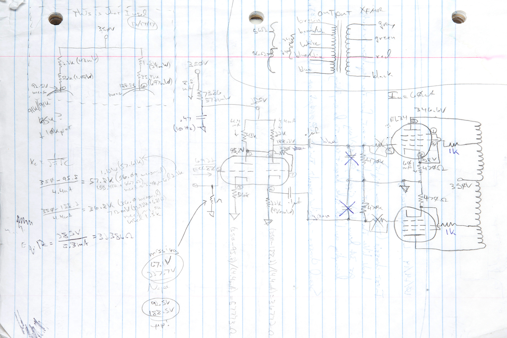
I’ll keep the description high-level. The first stage of the 6922 sets the bias point for the second stage, which gives us equal and complementary signals on the cathode and the plate of the second stage. Those signals drive the matched pair of EL34s, each of which are set with quiescent plate current of 60mA. I don’t have a bias adjustment installed (maybe later?), so the tubes have to be matched.
Logistics
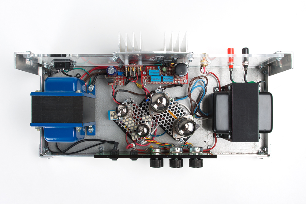
The layout of the chassis is nothing earth-shaking. Power (left) and audio (right) transformers are on opposite sides and orthogonal so as not to interfere with each other, tubes are in the middle, power supplies are to the back where I have access to a heat sink, and controls are to the front. As I mentioned earlier, the two monoblocks are book-ended, so everything you see here is swapped left-to-right on the unfinished one. The funny-looking thing that’s stood-off from the heat sink is my heater rectifier. I accidentally ordered the wrong package for those Schottky diodes (thought I was getting TO-220, ended up with DPAK), so I had to get clever with my heat dissipation. It works well enough for now, but I really need to get those things on the heat sink proper --- probably all four diodes on a single PCB flush-mounted to the heat sink.
The chassis itself is comprised of many pieces of metal bolted together. The difficulty with that is that I’ll need to periodically crank all the screws down to make sure everything is well-grounded. Also, the choice of using the green acrylic for a faceplate necessitates running a ground wire to each of the pot cases; otherwise you get a big “pop” in the output every time you touch one.
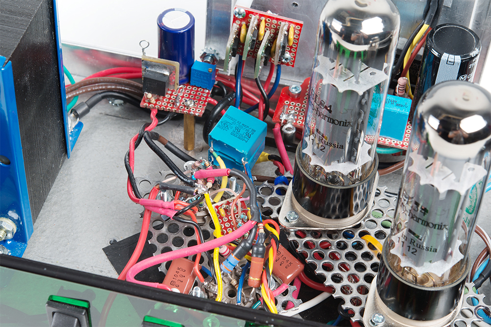
All the wiring is point-to-point. I like to keep my high-Z lines as short as I can, so components are mounted on the tube sockets. Morgan Jones would describe these examples as “howlers,” but I’m pretty careful keeping things secure and insulated because high voltage scares the bejesus outta me. If this were for production, I might do it differently.
Testing
If you read through my chicken-scratch schematics, you’ll see some notes and numbers indicating test measurements (DC bias points, really). But primarily, the difficulties I’ve run into are:
LT supply. How many times did I have to go around that block before I was happy? I lost count.
Missing grid resistor on the first stage of the 6922 messed up my bias points for both stages.
Plate current for the EL34s came in a little lower than expected at 55mA. It brings the bias point a little closer to a less active region, but it doesn’t seem to be a problem for the sound. I’ve also got 400 ohm resistors I can swap out for the 470s that are there now, and I’ve got plenty of headroom from my HT supply. But I won’t throw the power away if I don’t have to, in spite of all that junk I said about trading gain for BW.
60Hz everywhere. Everything’s got to be well-grounded, and all references must be shared. Don’t try to get clever with this; it will only make you cry.
Once all the 60Hz was gone from the output, the audio test yielded nothing displeasing. Is it a flat response? Well, I can make it flat with the use of the bass and treble controls, but the point of those is to make it sound how I like, and I don’t like a flat response. I tend toward the “smiley-face,” somewhat scooped mids, and I can dial that in without any trouble. And the amp has just enough non-linearities to sound like a tube amp. My nostalgia bone is well-satisfied.
I haven’t tested for power output. Well…I was listening to it in my basement the other night, and my wife later accused me of “rocking out down there” with something of a sneer in her voice. I’d call that a successful test.
Changes? Additions?
Besides the things I’ve already mentioned (updated heat sinking for the LT rectifier, bias adjustment for the EL34s)…
LEDs! Not addressable, flashy junk; that’s just gauche. But on my first design I had red LEDs illuminating the underside of the tubes to indicate low voltage presence. Then blue LEDs would illuminate the tubes when you had the HT turned on. I’ll probably do something similar here.
Bias monitoring at all stages. Also a thing I had set up on the last one, and it always kept me informed as to what the circuit conditions were, and would switch off the HT if something were dramatically out of whack.
Relay connection of the speakers to the output transformer. Again, had it in the first design; haven’t implemented here. There’s a big “pop” in the speaker when the HT gets turned on that I should make go away. Switching on the speakers after that power-up would fix it.
But these things are down the road a bit. For now, I’ll just be happy to have functioning amps. Finish the second one in 2--3 weeks? Dunno, man, I’ve also got a couple of new drone frames about to hit my doorstep, and it’s hard for the gnat to focus.
References
I’ve mentioned the name Morgan Jones a couple of times. If you’re interested in such esoterica as vacuum tubes, I’d highly recommend checking out his books.


Nice write-up. But I'm a bit confused with "LT" and "HT"... Is the "T" there "Tension" as in a nostalgic term for "Voltage"? Your younger readers might not figure this out if you don't define your terms...
Yep, you're exactly right. The "T" is for "Tension". It's difficult to determine where to draw the line on explanations for home page posts, so I made some things somewhat self evident. If it had been a tutorial proper, I would have expanded.
Pete, you are in a surprisingly unique position to actually do something about these audiofool nutjobs while benefiting the electronics hobbyist community in general. Might I suggest...
A Build Your Own Vacuum Tube kit; include a heating element, some electrode material, some glassware, an end-cap with contacts, maybe a punch to put holes in the electrode material for those without a laser cutter, and instructions
An open-source vacuum tube design that lets you toggle (that's right, toggle) between linear and non-linear response, illustrating the point that even vacuum tubes can respond with precision linearity devoid of "warm sound" response, if you care enough about the details to make it so
Great project. As you probably know, you're getting the pop when the HT comes on because the HT supply is solid state and comes up in a hurry--no cathod heaters to warm up. :-) Putting a relay on the speaker connections is a bad idea because of self-induction in the output transformer. It could easily exceed the max. plate voltage and blow the output tubes or a cap. One possible solution would be to use a use the regulator to switch on the HT gradually (say was a capacitor w/bleeder resistor chargers on the regulator input). Speakers should never be connected or disconnected from a tube amp while the amp is turned on.
P.P.S. Another reason to bring the HT up slowly is to the electrolytic caps time to polarize (especially if the amp has been shut off for a long time). Tubes worked good with tubes-- mixing them with solid state is a tricky business (as a lot of guitar amp designers have learned the hard way).
P.S. Normally there's no DC though the output xformer, so no big field. But funny things happen during start up, or when speakers are connected or disconnected. Also relays contacts can bounce. All it takes to get a big voltage spike is to get a field going and then suddenly collapse it. You're starting with 350 VDC...
Back when capacitors were physically large and expensive, the usual approaches to hum reduction were tapped heater windings and big inductors on the HT supply. I wonder if adding inductance on the LT supply would let you get more headroom. Somehow I'm guessing the physics of it would end up dictating an enormous hunk of copper and iron but I haven't done the math.
I appreciate your comments about the audiophile scams. My favourite was the $10,00 solid silver USB cable that apparently improves the musicality of digital sound.
Or if you want really good valve sound you could just buy a pair of old Quad IIs. I believe Quad have started manufacturing them again in China with modern connectors. Only 15W from a pair of KT66s (Class A ?) so you need efficient speakers. Goes nicely with a pair of Tannoy monitor Golds.
i look at tubes this way they are not dead there are just misunderstood i am doing the repairs ion a 65 year old Allen organ and it is all tubes and it has a better sound than the solid state one and easy to fix too
I once designed a very basic tube amp, using two 50C5s (one for each channel) and a 12AX7. The power supply was solid state (although I almost used a 5Y4 for the rectifier). I don't think I ever finished it, though.
Nice to see something old-school with no microcontrollers for a change!
I really love the layout. I've built a couple of tube amps based on Bruce Perens' "OddWatt" ultralinear design and been quite pleased with the results. However, I used a very conventional layout with tubes and trannys on top and wiring on the bottom. I really like the idea of exposing the wiring, at least for a "shop" system. I may try your approach next time with the perforated plates to mount the tubes.
It seems I can't embed images here, so no photos :( Or maybe there is a trick to doing this?
I've seen some examples built on 2x4's (OK, I've seen one, not multiple) with everything exposed. I'd never advocate something like that, cuz it's dangerous as [insert expletive of choice]. Everything's got to be secure enough that you can trust it won't ever move. When things pop, I scream like a child.
Yeah, I wish we could have pics in here, too. Dunno what that takes. But you can always post a link.
With Markdown, the trick is putting an exclamation mark in front of a link to an image
see https://daringfireball.net/projects/markdown/syntax#img for a better explanation
Huh. Well, i guess that's what it takes. Thanks for that.
The layout of the chassis is nothing earth-shaking. Power (left) and audio (right) transformers are on opposite sides and orthogonal so as not to interfere with each other, tubes are in the middle, power supplies are to the back where I have access to a heat sink, and controls are to the front.This circuit I found pretty nice that PETE-O
So, I am definitely interested in esoterica, such as, vaccum tubes lol, however, I too have a short attention span, and tubes seem quite elusive.
I bought an old AM Federal radio, stupidlly expecting all the parts to still be there and functioning lol, and that the radio would somehow transfer the knowledge of its makers design process by osmosis after I cracked the top off lol. Needless to say, this was not the case lol. About all I learned is point to point wiring is a pain to turn into aa circuit, and I am fairly certain the radio has a 3 stage design using 3 different pentode tubes. Eventually, I'd like to restore it one day.
As far as the Morgan Jones books go, I see four options. So, do you have a recommendation on which book for a tube newbie? I have some electronics knowledge, buy have much to learn in troubleshooting and design. Thanks for your time!
Can't wait to see the finished project! Have you thought about an external or internal addition to the project for Bluetooth audio? So your speakers could too be "convenient" lol xD
As it happens, Lectron offers a great set of electronic learning blocks, which include vacuum tube modules. You can even get vacuum tube breadboards from Modul-Bus.
Hum, thank you. I will have to check out both resources when I have a chance!
The books with "Building" in the title cover all the mechanical aspects of tube amps, the ones without cover circuit principles. I've got the first editions of both, don't know what's added for the second. But if you want to learn how tubes work (maybe a video to come?), get one of the editions of "Valve Amplifiers". I've got tons of post-its in my copy marking pages where I spent a lot of time.
Add BT? Yeah, sooner or later I'll probably do that. But they'll also be running off my desktop, more than likely, so I'm not sure what the point of BT would be.
Oh, ok thank you! I will have to do a little research then as to the best edition for both I guess. Yeah, I am sure I will have several pages marked as well, once I get a copy and understand the scope of tubes a bit better.
Yes, I know I would enjoy a tube video! Maybe you could talk about this project of yours, play us some of the audio from your amp or something, and explain the design process somewhat after an intro on tubes?
I actually found a funny, short, old video from Westinghouse on the 6 functions of tubes, and how to use them in each case haha. I would like to eventually build an oscilloscope out of tubes, that is the goal haha. My grandpa has one he built back in the 70s lol. I also, picked up another radio with tubes. This one is Realistic brand FM/AM (radio shack brand), not just AM like the other I have.
Yes, that is what I meant. That would be interesting to see haha. Oh, I gotcha, I have similar feelings about BT lol.
JFETs with pilot lights.
Lol yeah, i suppose.
Great write up! Do you think a non-tube amp can sound as good as this? Maybe that is a good challenge for you...
Depends on your definition of "good". Tube amps tend to be less linear that solid state and add some even harmonics to the signal, giving them a very particular sound. They can be made more linear (hence ultra-linear pentode configs, but even these aren't perfect), but it's more effort to make them so. There are much better technologies that convey truer sonic reproduction. But I happen to love the sound of a tube amp. So... better? It's in the ear of the beholder.