Enginursday: LED Guitar for Decadon
I was recently approached by music producer Decadon to add lights to an already custom guitar to make it even more one-of-a-kind. Let's check out some of the challenges I faced.

It's not every day you get handed a guitar that has only two others of its kind in the world, and it's an even rarer occasion when the owner trusts you to cover it in LEDs. In order to maintain this trust, I wanted to figure out some way to add the lighting effects that I wanted without affecting the structural integrity of the guitar whatsoever. I didn't want to drill into or glue onto the guitar due to the lack of an available second chance, so I came up with a plan to sandwich the guitar in between two layers and support my various lighting mechanisms through that.
Slicing the bread
If my guitar is a sandwich, then the bread is the guitar-shaped plexiglass cutouts on either side. To start mocking the shape up, I traced the guitar on a dry erase board with a marker, and measured the rough dimensions of the guitar. I then snapped a picture of this outline and dragged it into Illustrator. Tracing the outline of the guitar didn't yield perfect results; I probably sliced about 30 "guitars," moving a line here, nudging a hole there, before I got that wacky shape figured out.
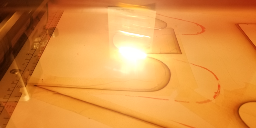
Laser-cutting the guitar shape
Once I had that sorted, I had to figure out a way to get that bread stuck together. To do this, I added tabs along the outside (in strategic points, which I'll talk about later). Once I had these tabs attached I was able to sandwich the guitar in between my "slices of bread" and get things attached to the guitar.
It's not just a screen, right?
I wanted some aspect of this guitar to be new and novel, so I figured I'd add some fiber optic around the edge of the instrument to give it that unique extra touch. Remember how earlier I mentioned that the tabs had been strategically placed? I placed the tabs at inflection points on the guitar, as I'd have to mount the fiber optic to these tabs, and mounting at those inflection points (where a line changes its curvature) will keep the fiber as close as possible to the body of the guitar.
I also wanted an unbroken line of light around the edge of the guitar. To create this effect, I used a double stranded twist of fiber optic along with a clever mounting solution. The issue with lighting fiber optic via LED is that you have to relight the fiber every foot or two depending on the amount of bend and desired brightness. This usually means that every time you relight the fiber optic, you have a dark spot in your line where the lighting module sits. To combat this, I have a double stranded twist of fiber optic; each lighting module sits on a tab in between the "slices of bread" and pumps light into just one strand of the twist, while the other strand passes unbroken over the top. This setup allows me to keep the whole edge lit with seemingly no interruptions.
Now you may notice that the fiber optic runs down the neck of the guitar and you might be thinking, "Hey Andy, I can't play guitar with that in the way!" and to that I say yeah, you know what, you're probably right. Due to that this little feature might not be on the final product, but I'm gonna test it with the artist and see if it's playable, and if not, hey it looks pretty sweet for now.
Mocking up a pixel layout
I didn't want to over- or under-order my pixels, and I also wanted to have an idea of how I would transmit data to the array, so I wanted to mock up the array before laying pixels down. To do this, I created a mock-up of an SK6812 skinny pixel strip, printed a whole bunch out, then carefully cut and laid them down on a cardboard cutout of the guitar shape. I then numbered the pixels and decided how I'd send all the data (I eventually settled on three strips of LEDs).
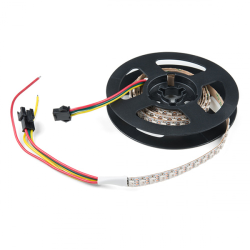
Once I had my rough mock-up completed I ordered around 1600 SK6812 LEDs and set about cutting and soldering the strips onto one of the plexiglass "slices of bread." Note that power does not need to necessarily follow a particular direction; you can connect the power/ground of any strip to the power/ground on any other part of the next strip. This is unlike data, which must zig-zag down the array so data reaches every pixel.
Ground first! Make sure to connect the ground of your LEDs before hooking up any other connections.
Help me, my pixels are flickering
That's not enough info, you're gonna need to tell me a little bit more. Flickering is usually caused by a loose connection – you can usually tell which connection is loose upon visual inspection of your flicker.
- Pixels only glow a dull red, and change with the rest of the pattern - Inspect your ground connections; your circuit is powered but not complete.
- Pixels intermittently change with the pattern - Inspect your data connections; you probably have a loose data line.
- Pixels just go berserk - Your circuit is probably grounded, but not grounded well to the microcontroller or some of the strips near it.
- Intermittent white flash every 5-10 seconds - Are you using 3.3V logic? Either convert it up to 5V logic or you can (cheat) turn the supply of your LEDs down to around 4.3V, which will put 3.3V within the logic levels accepted by the LEDs.
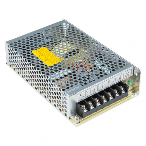
That's a lot of LEDs, mind elaborating on all that wattage in the cottage?
This project is a pretty large one, involving a TON of SK6812 LEDs. In fact, at full white, I could hypothetically be yanking nearly 500W. This being said, these LEDs are actually a little painful to look at when you make them vomit as many photons as possible, so for a screen application, it's good to bring them down to about 25 percent brightness (I did all my debugging at 12.5 percent to avoid blindness) to allow for a sane amount of light to enter the retinas of your audience. However, the LEDs in the fiber optic should run at full brightness as the fiber diffuses the bare LED quite well.
Speaking of diffusion, nobody likes looking at bare LEDs right? Right. In order to add a little bit of diffusion and also clean up the look of the project, I snagged this neat, heat-activated fabric called Wonderflex and formed it over my custom screen once I made sure all of my solder joints were properly done. This step was quite a lot easier than I thought it would be, just 180°C from my heat gun and bend. The finished product looks a bit better than bare LEDs.
This test code looks like Juicy Fruit
I got a little bit sick of staring at the rainbow, so I figured I'd try and generate some other good-looking gradients. Inspired by Felipe Pantone's artwork in which he stacks color waves on top of one another, I decided to take a similar approach. What I did first was create a sine wave for red, green and blue, then I randomized the amplitude and frequency of each wave and stacked them on top of each other. I reshuffled my frequencies and amplitudes once all combinations of the waves had been displayed. The result is quite stunning and generates a bunch of natural-looking gradients that I would never have come up with on my own. Pipe this code into your own LED strips and let me know what you think!
#define FASTLED_ALLOW_INTERRUPTS 0
#include "FastLED.h"

// How many leds in your strip?
#define NUM_LEDS_LOWER 315
#define NUM_LEDS_NECK 600
#define NUM_LEDS_PLATE 672
#define NUM_LEDS_RIM 24
#define TOTAL_LEDS  NUM_LEDS_LOWER + NUM_LEDS_PLATE + NUM_LEDS_NECK

#define DATA_PIN 23
#define DATA_PIN_2 18
#define DATA_PIN_3 13

// Define the array of leds
CRGB ledsLower[NUM_LEDS_LOWER];
CRGB ledsNeck[NUM_LEDS_NECK];
CRGB ledsPlate[NUM_LEDS_PLATE];

uint8_t rotation = 0;
uint8_t offset;
float newRedAmplitude = 3;
float newGreenAmplitude = 4;
float newBlueAmplitude = 5;
float oldRedAmplitude = 3;
float oldGreenAmplitude = 4;
float oldBlueAmplitude = 5;
int newRedFrequency = 3;
int newGreenFrequency = 4;
int newBlueFrequency = 5;
int oldRedFrequency = 3;
int oldGreenFrequency = 4;
int oldBlueFrequency = 5;

void setup() {
  Serial.begin(115200);
  Serial.println("resetting");
  pinMode(DATA_PIN, OUTPUT);
  pinMode(DATA_PIN_2, OUTPUT);
  pinMode(DATA_PIN_3, OUTPUT);
  LEDS.addLeds<WS2812,DATA_PIN,GRB>(ledsLower, NUM_LEDS_LOWER);
  LEDS.addLeds<WS2812,DATA_PIN_2,GRB>(ledsNeck, NUM_LEDS_NECK);
  LEDS.addLeds<WS2812,DATA_PIN_3,GRB>(ledsPlate, NUM_LEDS_PLATE);
  FastLED.setBrightness(64);
  randomSeed(analogRead(4));
}

void stackSines ()
{
  for (int strip = 0; strip < 3; strip++)
  {
    uint16_t NUM_LEDS;
    switch (strip)
    {
      case 0:
      NUM_LEDS = NUM_LEDS_LOWER;
      break;
      case 1:
      NUM_LEDS = NUM_LEDS_NECK;
      break;
      case 2:
      NUM_LEDS = NUM_LEDS_PLATE;
      break;
    }
    for (uint16_t ledPosition = 0; ledPosition < NUM_LEDS; ledPosition++)
    {
      offset = (ledPosition / 4) + rotation;
      uint8_t redFrequency = cubicwave8(offset * newRedFrequency);
      uint8_t greenFrequency = cubicwave8(offset * newGreenFrequency);
      uint8_t blueFrequency = cubicwave8(offset * newBlueFrequency);
      switch (strip)
      {
        case 0:
        ledsLower[ledPosition] = CRGB(newRedAmplitude * redFrequency, newGreenAmplitude * greenFrequency, newBlueAmplitude * blueFrequency);
        break;
        case 1:
        ledsNeck[ledPosition] = CRGB(newRedAmplitude * redFrequency, newGreenAmplitude * greenFrequency, newBlueAmplitude * blueFrequency);
        break;
        case 2:
        ledsPlate[ledPosition] = CRGB(newRedAmplitude * redFrequency, newGreenAmplitude * greenFrequency,           newBlueAmplitude * blueFrequency);
        break;
      }
      if (offset == 0 && ledPosition == 0)
      {
        frequencyShuffler();
      }
    }
  }
  FastLED.show();
  rotation++;
  delay(10);
}

void frequencyShuffler()
{
  uint16_t shift = 0;
  float newAmplitudeVal;
  int newFrequencyVal;
  for (int i = 0; i < 3; i++)
  {
    newAmplitudeVal = random(0, 255) / 255.0;
    newFrequencyVal = random(2, 14);
    switch (i)
      {
      case 0:
      newRedAmplitude = newAmplitudeVal;
      newRedFrequency = newFrequencyVal;
      break;
      case 1:
      newGreenAmplitude = newAmplitudeVal;
      newGreenFrequency = newFrequencyVal;
      break;
      case 2:
      newBlueAmplitude = newAmplitudeVal;
      newBlueFrequency = newFrequencyVal;
      break;
    }
  }
}
Going further
Any project always has room for improvement, and with this one there are a couple things I'd like to see. The first thing would be a tighter pixel density for the face of the guitar. The second would be to continuously shuffle the frequencies and amplitudes such that the waves are constantly shifting their shapes and sizes. The next effect I was going to add was varying speeds and directions on each of the waves to allow even more variability. Getting all of these things implemented would make a seriously good-looking effect for LED strips. If you have suggestions for wacky color patterns or functions you like to run on your LEDs let me know in the comments below.
Interested in learning more about LEDs?
See our LED page for everything you need to know to start using these components in your project.


higher density? DO IT ;-)
--> use the APA102 2020 LEDs (2x2mm) :-)
as they have SPI-like clock and data separated...
multiple options to use them:
you can try and ask theme if its possible to get <=3mm pitch (let us know the answer ;-) )
could be challenging to cut and reconnect then...
regarding power
best case would be to have a 24V or higher supply line that goes up to the guitar -
and then use several step-down (buck regulators) to translate down to 5V with high-amps output..
i would target 10A per regulator - this way from the power point of view you can split up your hole screen in parts - and if something goes wrong only 10A can smoke - and not 100A...
up till know i did not find any fitting ready made (small sized) modules for this..
but there are controller chips for this kind of thing out there...
if anyone wants more info on what i have found/researched so far let me know. and i will dig for my text file... ;-)
First of all - WOW! What a great project. I wondered if you could share the exact DMX Controller & Decoder you used for this project. I’d like to try to replicate what you’ve done. TIA!
Would you guys consider running ColorChord on this with the guitar being the input? I would be more than happy to help collab/with the setup. ColorChord on a Guitar or ColorChord on a Saxophone
I'll probably create something similar to colorchord, just running FFT on an ESP32 and outputting that to the lights.I'd like to avoid using a laptop if at all possible as I'd like the microcontroller to be able to handle several different modes (colorchord-esque mode, presets, and DMX input)
Great project!
One tidbit conspicuous by its absence is mention of what processor you used.
I'm afraid I'd be distracted from playing the guitar by the flashing lights on it. Hope that the guy for whom you're doing this won't have that problem! (It may explain why I'm a LOT better at electronics and programming than I am at playing the guitar!)
Thanks! For the demo in the video I used an ESP 8266 but for the final build I'm using an ESP32. I discovered a timing issue with multiple strips on the ESP32 the day I filmed (demos never work) also, the WS2812/SK6812 has quite finicky timing as it has an internally generated clock which must be matched by your microcontroller.
Anyway I totally agree with the flashy lights comment, I've been distracted just trying to program the thing and that was before it looked this good so I'm excited to see how the patterns on the guitar and the artist coexist in a live show environment!
One thought: There are folks who like to put on some really fantastic "Holiday Displays", making lights on their houses "dance" to the music. Although these are "fixed programs", and are just time-sync'ed to the music, rather than responding to the music, looking at the GUI for the software might give some inspiration. Sorry, I don't recall the names of the programs off hand, and the one guy I knew who was really into it here in the Phoenix area has moved back to Pennsylvania. He did give a presentation to the ham radio club we were both in about once every other year while he was here. (He also said that the most expensive part of his display was all of the extension cords!)
Yeah, I'm familiar with the timing issues on the NeoPixels. (That's partly why I asked!)
Dude, so rad! Can you make one for me??!! First thing I'd want to do is link the light effects to each of my effects pedals. And get it to react to what I was playing with one of these. How is power gonna make it's way up to the guitar?
Linking up to the pedal would be sweet!! I dig that idea, and I just got out of guitar land Pete don't drag me back in... I'd absolutely be willing to assist and give you some more tips on paint points I had.