Python and the SparkFun LumiDrive
If you're looking to try coding in Python, especially as it translates to the world of physical computing, the SparkFun LumiDrive is a great way to get started.

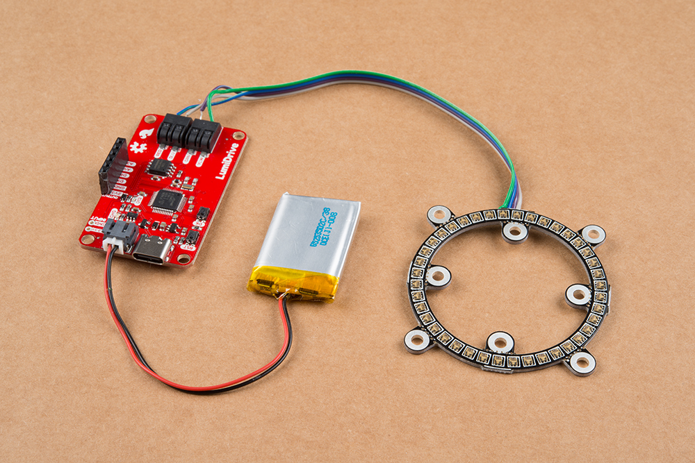
This past week, we released our new LumiDrive LED Driver board. This board should please a lot of folks who have been asking for an LED controller that could run Python or one of its board-based variants. This is made possible because the LumiDriver has an onboard SAMD21 which, unlike the ATMega328P, has the speed, power and size to run Python. So now that we have it, what can we do with it? I’m going to offer a very simple introduction for those out there who are unfamiliar with, or at least very new to, the Python environment. Let’s get started.
This could be the start of something big. ~Steve Allen
Let’s start at the very beginning
Since we’re starting out simply, let’s take a look at one of the simpler Python editors - Mu. If you’re already completely comfortable with Python, this editor will probably seem restrictive, as it limits itself to only the most essential features. Of course, if you’re already comfortable with Python, you’re probably already using Visual Studio Code, EMACS, VIM, Code Writer or any other more powerful code editor, and doing much more than will be covered here today. From the Code with Mu page, click the download button and you’ll be brought to the download page. Download and install the version appropriate for your system. When you open the program, you’ll be greeted with the coding window.
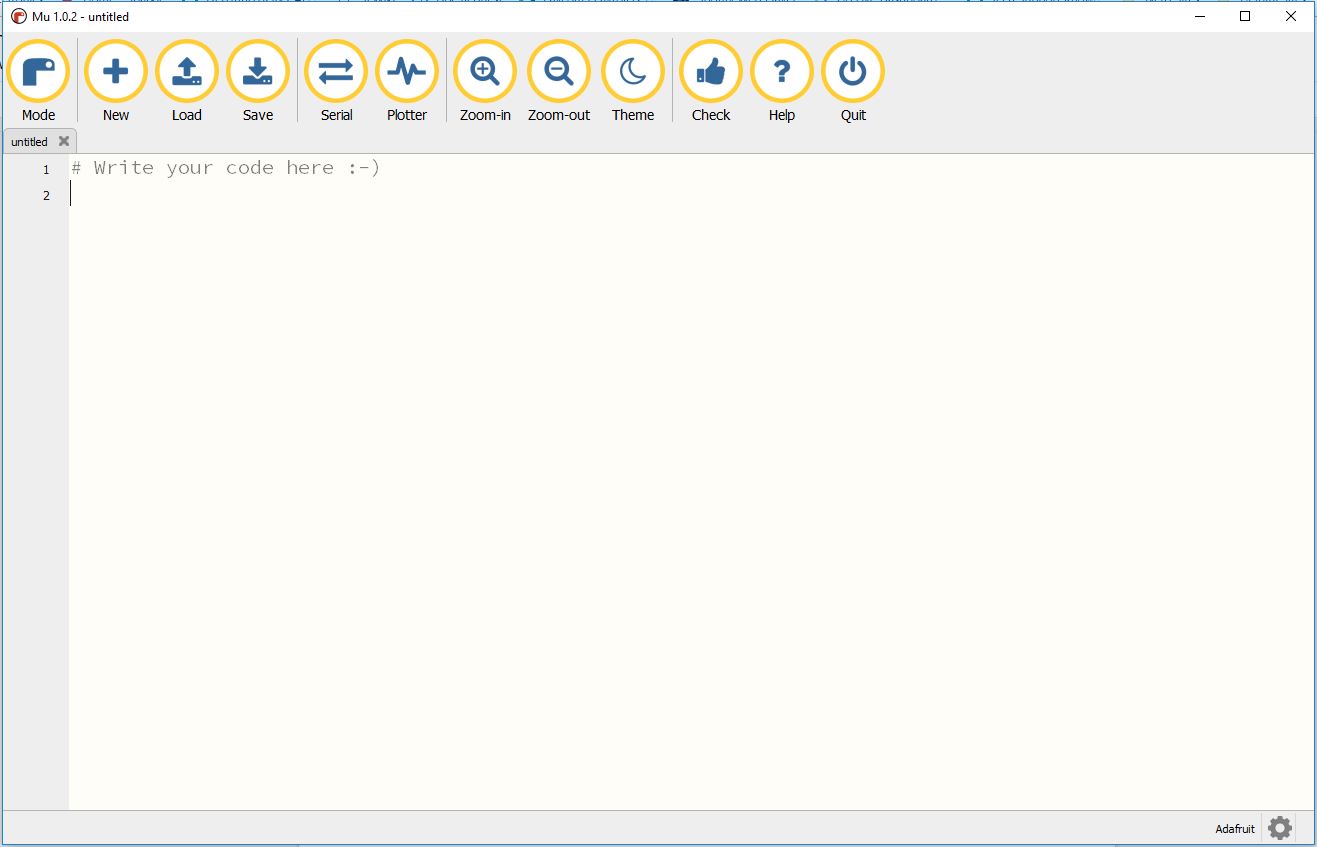
While Mu may look simplistic, it offers all you will need to start learning the very basics of Python programming, and getting your project lit!
The first thing you may notice is the large, simplistic looking buttons across the top, and the lack of dropdown menus above that. This is by design. Remember, Mu is geared towards those just starting out with Python, so its aim is to allow people to simply focus on the very basics without overwhelming them with all of the options, features and possibilities they will eventually need.
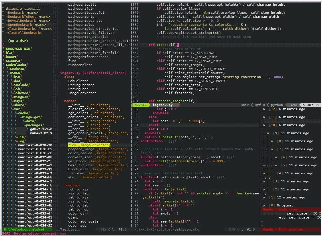
While Vim is a great editor, its “movie hacker breaking into a secure server” look can be intimidating to anyone just starting out. (Image via slant.co.)
First look
If you plug in your SparkFun LumiDrive LED Driver, you should see a new window open, named CircuitPy. You can now write your code directly to the LumiDrive itself. Your LumiDrive came with a few necessary files pre-loaded, included one called main.py. This is where you'll find the code your LumiDrive will run (note: You could also use code.py, as well as main.txt or code.txt. These files will be automatically detected, and the board will run them as soon as they're detected, but it will only run one. A quick test here seems to indicate that it chooses the one that is first alphabetically). If you click on the Load button at the top of Mu, you can navigate to your CircuitPy drive, open main.py and edit it directly.
Now you may look at the 174 lines of code, then glance back at the board doing nothing more than blinking its on-board blue LED on and off every half second, and think to yourself, that is a whole lot of code to be doing a whole lot of not much. But if we look closer, we can see that most of that code is a series of functions. In Python, a function is a block of code that only runs when it is called. Each function is defined using def.
def a_small_function():
    print("My, what a lovely function")


while True:
    a_small_function()
In this instance, while True: acts just like void loop() does in your Arduino code. Knowing that, we can trim down the main.py code to just a handful of lines, and get the same output.
import time
import board
import digitalio

# Setting up the board's blue stat LED to blink
led = digitalio.DigitalInOut(board.D13)
led.direction = digitalio.Direction.OUTPUT

#Ah trusty ol' blink.
while True:
    led.value = True
    time.sleep(.5)
    led.value = False
    time.sleep(.5)
Taking control
So let's say you don't want the on-board LED to blink mindlessly on its own, but you want to take control of it. Let's use the on-board button to accomplish this. The button on board the LumiDrive is attached to D6, so we'll need to establish this in our code in the same way we established the on-board LED. We define its pin number, its direction, and in the case of our button, that it is pulled HIGH so that it isn't floating.
import time
import board
import digitalio

# Setting up the board's blue stat LED to blink
led = digitalio.DigitalInOut(board.D13)
led.direction = digitalio.Direction.OUTPUT

#Setting up the board's onboard button
button = digitalio.DigitalInOut(board.D6)
button.direction = digitalio.Direction.INPUT
button.pull = digitalio.Pull.UP

# Here's whare the action happens
while True:
    if button.value:
        led.value = False
    else:
        led.value = True

    time.sleep(0.01) #debounce delay
< click > Light goes on. < click >Light goes off. < click > Light goes on. < click >Light goes off.
I've written the if: else: code like this to show you what's going on, but Python allows for a simpler way to accomplish this. Since we're really just saying, "When the button is pulled HIGH, the LED should be LOW; while the button is pressed LOW, the LED should be HIGH," we can simplify the code, like this:
while True:
    led.value = not button.value  #LED state is always opposite button state

    time.sleep(0.01) #debounce delay
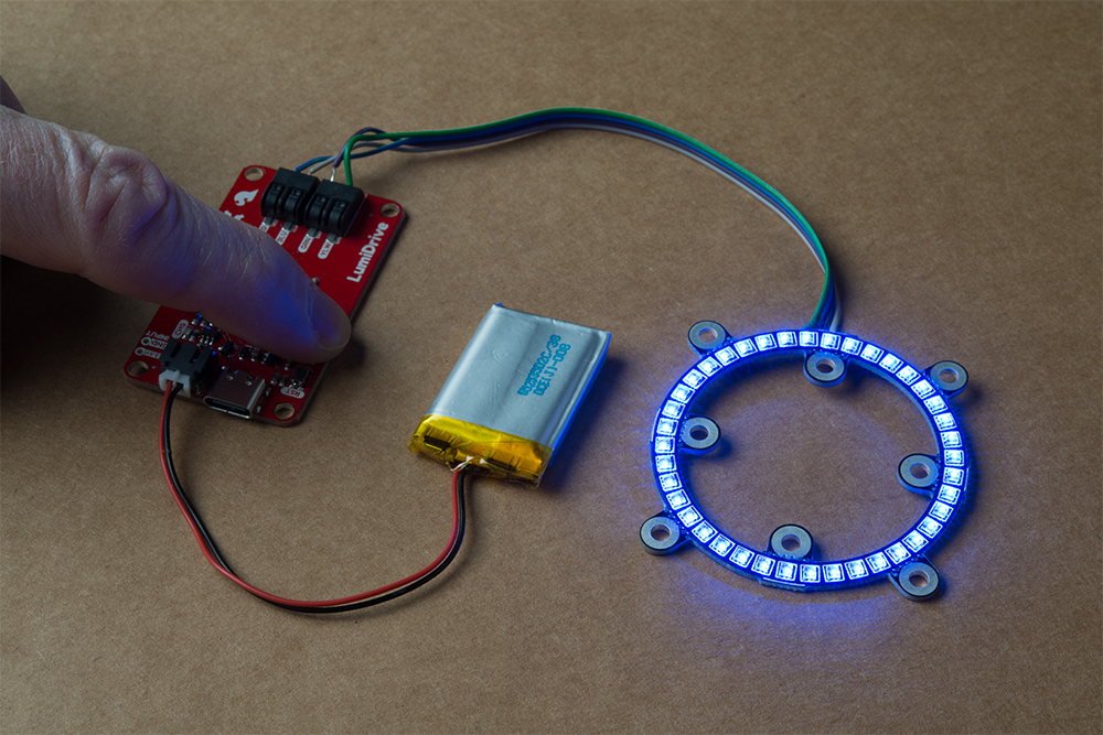
Moving off the board
Now let's expand beyond the on board, and branch out. Since the LumiDrive pairs perfectly with our new LuMini LED Rings, we'll add one of those. The Hookup Guide will get you soldered up and give you a great start, and we're going to use some of that code here, but rather than let it go on its own, we'll add button control.
Just like we did with the on-board LED and button, we'll need to give the board all the information it needs on the LuMini Ring - the library we'll be using, how many LEDs there are, how bright we want them, etc. All of this was in the initial main.py file that came on your LumiDrive board, but if you've overwritten it while experimenting here, you can always grab it from our GitHub repo. Remember the functions we talked about earlier? Well here's where they come into play. For the sake of simplicity and ease of reading, I'm only going take one of the functions, but we'll have to make some declarations so the code knows what is expected of it. Let's go with the very basic color_fill function and a couple of standard colors as we define them in the code.
import adafruit_dotstar # The LED library
import math
import time
import board
import digitalio

# Setting up the board's blue stat LED to blink
led = digitalio.DigitalInOut(board.D13)
led.direction = digitalio.Direction.OUTPUT

#Setting up the board's onboard button
button = digitalio.DigitalInOut(board.D6)
button.direction = digitalio.Direction.INPUT
button.pull = digitalio.Pull.UP

# These two variables should be adjusted to reflect the number of LEDs you have
# and how bright you want them.
num_pixels = 60
brightness = 0.25

# This creates the instance of the DoTStar library.
pixels = adafruit_dotstar.DotStar(board.SCK, board.MOSI,
    num_pixels, brightness=brightness, auto_write=False)

# Some standard colors.
BLACK = (0, 0, 0)
RED = (255, 0, 0)
YELLOW = (255, 150, 0)
ORANGE = (255, 40, 0)
GREEN = (0, 255, 0)
TEAL = (0, 255, 120)
CYAN = (0, 255, 255)
BLUE = (0, 0, 255)
PURPLE = (180, 0, 255)
MAGENTA = (255, 0, 20)
WHITE = (255, 255, 255)

# This function takes a color and a delay and fills the entire strand with that color.
# The delay is given in the case you use multiple color fills in a row.
def color_fill(color, wait):
    pixels.fill(color)
    pixels.show()
    time.sleep(wait)

# Here's whare the action happens
while True:
    if button.value:
        led.value = False  #I've kept the onboard LED involved for testing purposes
        color_fill(BLACK,0)
    else:
        led.value = True
        color_fill(BLUE,0)

    time.sleep(0.01) #debounce delay
I said we would be using a couple of the standard colors as we've defined them, but the LED ring just turns on one color, and then turns off. That's because the second color (or first, depending on how you look at it) is BLACK, which we've defined as (0, 0, 0). And if you want to get crazy, you could define any color in this way. If you do a Google search for "rgb color picker," you'll be presented with a really nice tool that will allow you to chose any color, and it will return not only the RGB value, but also HEX, HSV, HSL and CMYK. Want to add a rich purple to your palette? In your color definitions, just add PURPLE = (133, 6, 224), and you can now call that color just like the others.
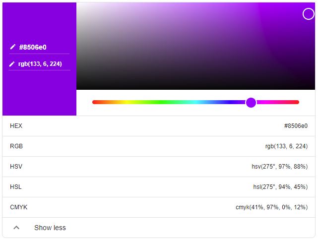
With the slider for hue, and the circle for saturation and value, you can easily get the values for RGB, HSV, or whatever format you're using in your code.
Multiple options
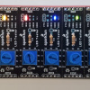
With multiple digital pins, why not use multiple buttons? It's really simple, thanks to Pythons elif command. As I'm sure you can figure out, this is just a shortening of what would be else if in Arduino code. The elif statement allows you to check multiple expressions for TRUE and execute a block of code as soon as one of the conditions evaluates to TRUE. So let's whip up a quick circuit, and throw a little code together. Attach a pair of momentary buttons to D8 and D9 (and to GND). I've soldered female headers to my LumiDrive to make prototyping easier, but if you're sure you want a momentary button on each of the two digital IO pins, you can just solder straight to the board. The code is changed slightly, to set up the two digital IO pins. I've also added another one of the functions from the initial demo, just to make it a little more interesting.
import adafruit_dotstar # The LED library
import math
import time
import board
import digitalio

# Setting up the board's blue stat LED to blink
led = digitalio.DigitalInOut(board.D13)
led.direction = digitalio.Direction.OUTPUT

#Setting up the board's onboard button
button6 = digitalio.DigitalInOut(board.D6)
button6.direction = digitalio.Direction.INPUT
button6.pull = digitalio.Pull.UP

# Setting up the digital IO pins as input buttons
button8 = digitalio.DigitalInOut(board.D8)
button8.direction = digitalio.Direction.INPUT
button8.pull = digitalio.Pull.UP

button9 = digitalio.DigitalInOut(board.D9)
button9.direction = digitalio.Direction.INPUT
button9.pull = digitalio.Pull.UP

# These two variables should be adjusted to reflect the number of LEDs you have
# and how bright you want them.
num_pixels = 40 #The 3" ring has 60, the 2" ring has 40, the 1" ring has 20
brightness = 0.25

# This creates the instance of the DoTStar library.
pixels = adafruit_dotstar.DotStar(board.SCK, board.MOSI,
num_pixels, brightness=brightness, auto_write=False)

# Some standard colors.
BLACK = (0, 0, 0)
RED = (255, 0, 0)
YELLOW = (255, 150, 0)
ORANGE = (255, 40, 0)
GREEN = (0, 255, 0)
TEAL = (0, 255, 120)
CYAN = (0, 255, 255)
BLUE = (0, 0, 255)
PURPLE = (180, 0, 255)
MAGENTA = (255, 0, 20)
WHITE = (255, 255, 255)
PURPLE = (133, 6, 224)  # We added this from the RGB Color Picker, remember?!

# This function takes a color and a dely and fills the entire strand with that color.
# The delay is given in the case you use multiple color fills in a row.
def color_fill(color, wait):
    pixels.fill(color)
    pixels.show()
    time.sleep(wait)

# The travel function takes a color and the time between updating the color. It
# will start at LED one on the strand and fill it with the give color until it
# reaches the maximum number of pixels that are defined as "num_pixels".
def travel(color, wait):
    num_pixels = len(pixels)
    for pos in range(num_pixels):
        pixels[pos] = color
        pixels.show()
        time.sleep(wait)

# Here's where the action happens
while True:
    if not button8.value:
        led.value = True
        travel(YELLOW,0)
    elif not button9.value:
        led.value = True
        travel(GREEN,0)
    elif not button6.value:
        led.value = False
        travel(PURPLE,0)
    else:
        led.value = False
        color_fill(BLACK,0)

    time.sleep(0.01) #debounce delay
What next?
This should give you a decent start adding a little input and gaining a little control to your LumiDrive board. Play around, experiment and remember it's always a good idea to back up your code so you can always return to a working point if things go terribly sideways. Next week, we'll look at adding analog input and then, if all goes well, put it all together into a practical build of some sort.


I wasn't able to get the google search driven color picker using your search term. But, this one worked: color picker tool