
Introduction
Howdy folks! I'm Dryw, a new engineer here at SparkFun! I joined in March of this year and have already released a handful of products, such as those Bosch pressure sensors and the IoT Redboard - ESP32. I've also been working on some more exciting products that will be coming out soon, stay tuned for those!
As I've been working here, I've noticed a lot of our products use different resistor values for LEDs. Consistent LED brightness hasn't been a critical design requirement for us, which has resulted in different brightnesses across our catalog. The most severe example I saw was on a prototype, where the green and yellow LEDs were barely visible, and the red and blue LEDs felt like staring into the sun! So I made it my mission to find the perfect resistor for each of our LEDs, in order to give a consistent brightness across all our products, and to never need sunglasses ever again!
Problem Definition
This is a fairly simple problem to solve, so you might be thinking "just look at the LED's datasheet and compute the ideal resistor with Ohm's Law." You're absolutely right, and that would be a totally valid approach. However there are some nuanced human factors that make this more tricky than it first appears:
- Different colors are not all perceived equally. For example, human eyes are most sensitive to green light, so they will appear to have a different brightness than red or blue LEDs despite having the same absolute brightness.
- The size of the LED affects the perceived brightness. For the same absolute brightness, larger LEDs appear dimmer due to the light being produced over more surface area.
- Different cone angles change the amount of light that actually hits your eye. Some LEDs produce light in a very narrow cone, while others spread the light more evenly in all directions.
- Most LED datasheets rate their brightness in millicandela (mcd), and I've got no intuition for how bright a millicandela is!
- Different people want different brightnesses. In my testing (see below), there was a wide range of brightnesses that people preferred.
- Different ambient lighting conditions require different LED brightnesses.
On top of that, there are some additional technical considerations:
- Each color requires a different voltage. Shorter wavelength photons are more energetic, so blue LEDs typically require a higher voltage than red LEDs to turn on. This is also known as the "forward voltage drop" of the LED.
- Different colors require different amounts of current to produce the same brightness. In my testing, green LEDs usually required much more current than red or blue to achieve the same brightness.
- The same LED produced by different manufacturers have different brightnesses for the same currents. The most extreme example I found was between the green LEDs we use; at 20mA, one has a rated brightness between 5-12mcd, and the other is rated between 18-71mcd!
In principle, all these factors could be considered and accounted for. But in my opinion, it's much better to just play with the LEDs themselves so there's no doubt about the perceived brightness. So I got to work figuring out the best way to test each of our LEDs.
Solution
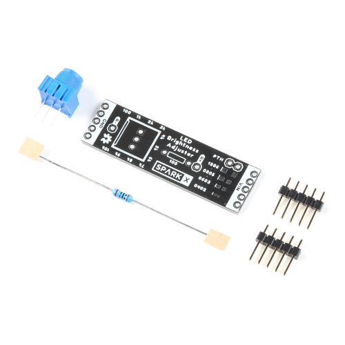
All the LEDs we tend to use are surface mount, so I needed to create a custom PCB to test them. In fact, we actually use 3 different sizes of LEDs, including 0402, 0603, and 1206. So rather than making different PCBs for each, I figured I could include each of those footprints in parallel on a single board. And heck, while I'm at it, why not add an 0805 footprint and some plated through-holes for LEDs with legs! Then we could test any LED!
In series with those LED footprints, I included a potentiometer as an adjustable resistor. I knew we wouldn't need to exceed 10k, so I used our blue 10k trimpot. It goes all the way to 0 Ohms at the low end, so I also included a 100 Ohm resistor in series to prevent any LEDs from blowing up. Here's what the schematic looks like:
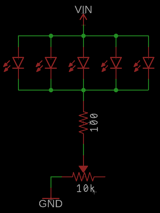
To be clear, only 1 LED is added to each board. There are just 5 different footprints to accommodate any LEDs.
Next step was laying out the board. As I played with it, I was settling on a thin PCB that was a bit under 2" long. That got me thinking... pulls out ruler and a breadboard... Aha! Solderless breadboards have power rails that are just under 2" apart from each other! That would enable a user to have several boards plugged into and powered by a single breadboard's power rails! I really love solderless breadboards, so this was perfect!
However, this lead to a question that's surprisingly hard to answer: What's the spacing between those power rails? You'd probably assume it's on a 0.1" grid, but it's actually not! A quick Google search yields very few useful results, some of which didn't agree with each other. They're usually within the range of 1.85" to 1.9" between the outer rails, so I measured my own breadboard:
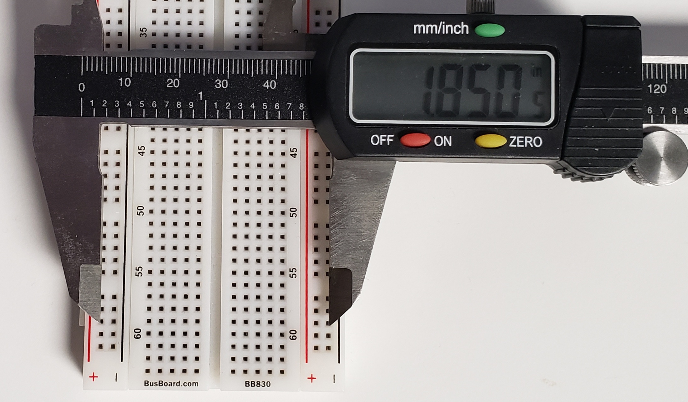
I measured a few other breadboards around the office, all were very close to 1.85", so that's what I settled on. There may be some breadboards that are slightly different, but the PCB uses header pins to slot into the power rails, which could bend slightly if needed. I also chose to use a row of 5 header pins on each end, since that's the standard grouping size of the power rails, and more headers make the boards more stable. That lead to this final layout:
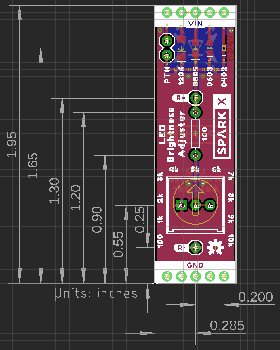
I also added some silkscreen around the potentiometer to indicate the approximate resistance as the knob is rotated; the arrow on those blue potentiometers is a great feature for pointing to those marks! However mechanical tolerances and parallax make the precise resistance hard to read, so I also added some test points ("R+" and "R-") for measuring the exact resistance with a multimeter.
Note - you'll see multiple versions of the board in this post. Some are of the initial prototypes, some are of the final product. More details are at the end of the post!
Testing
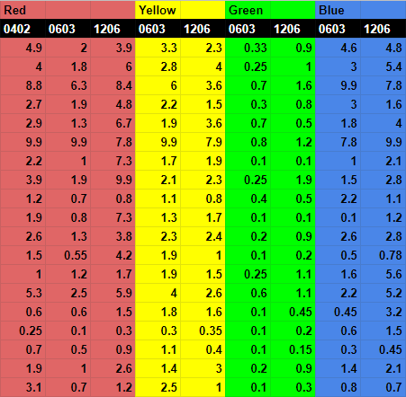
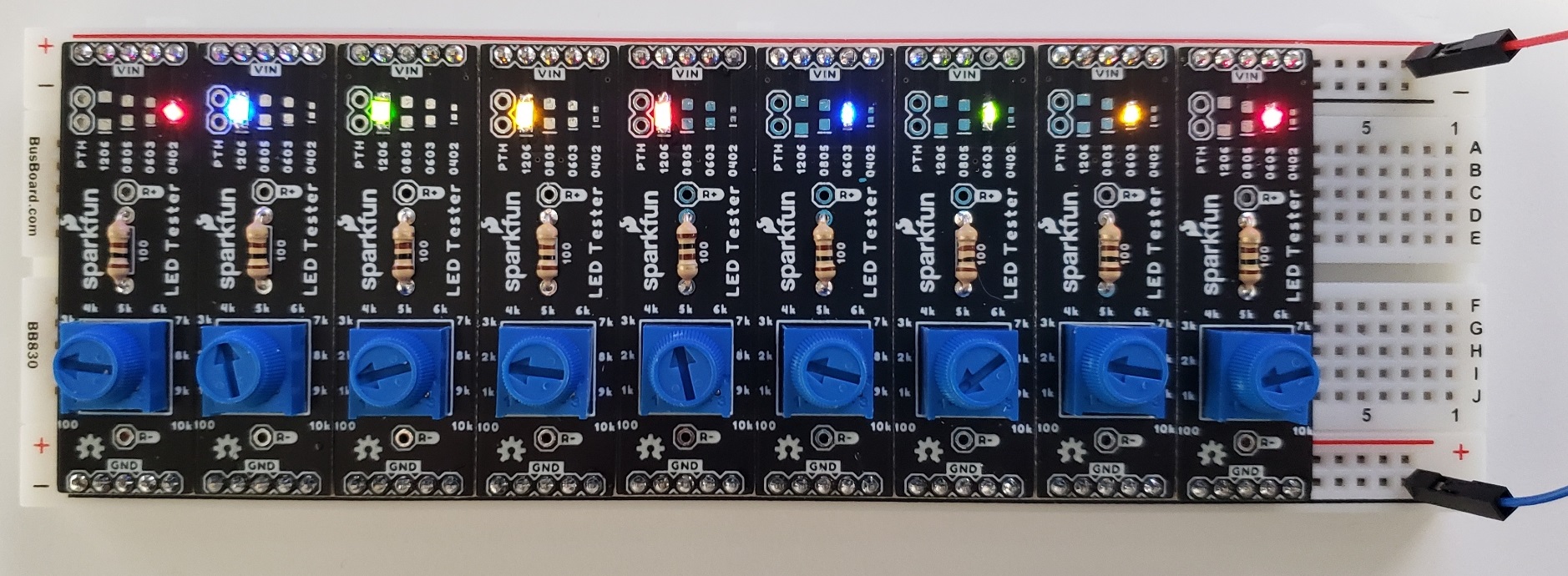
Once the PCBs arrived, I grabbed our most commonly used LEDs, inlcuding a 1206 and 0603 of each red, yellow, green, and blue, plus a red 0402. That makes 9 boards, which I soldered together and stuck into a breaboard. I set the input voltage to 3.3V, and each potentiometer to 1k for comparison:
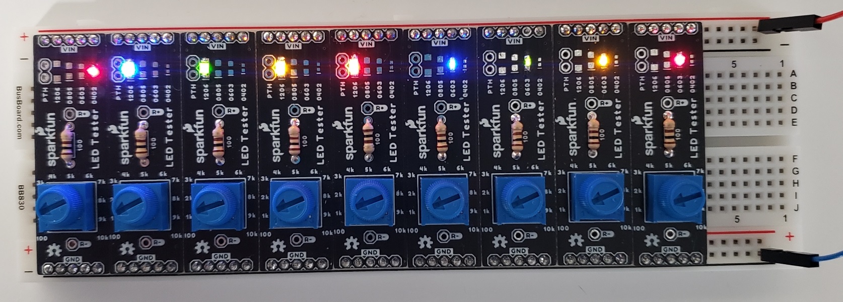
Same Resistance (1k) - Uneven Brightness
First off, I love how this looks! I've not seen a breadboard application that exclusively uses the power rails, but they sure are handy for this! Second, there's a lot of variance between these LEDs. The image doesn't quite match reality, but you can tell that green 0603 on the right is way dimmer than the rest, and the blue 1206 on the left is completely saturating the camera sensor. Time to start tuning!
I didn't want to be the one to dictate the "best" brightness, so I surveyed several people around the office. I had them all adjust the brightness of each LED until they were happy with it, and I recorded the resistance they set for each (3.3V input). Here's my data:
As much as I love staring at numbers, it's usually best to visualize them in some way. So I made a histogram of each column to compare:
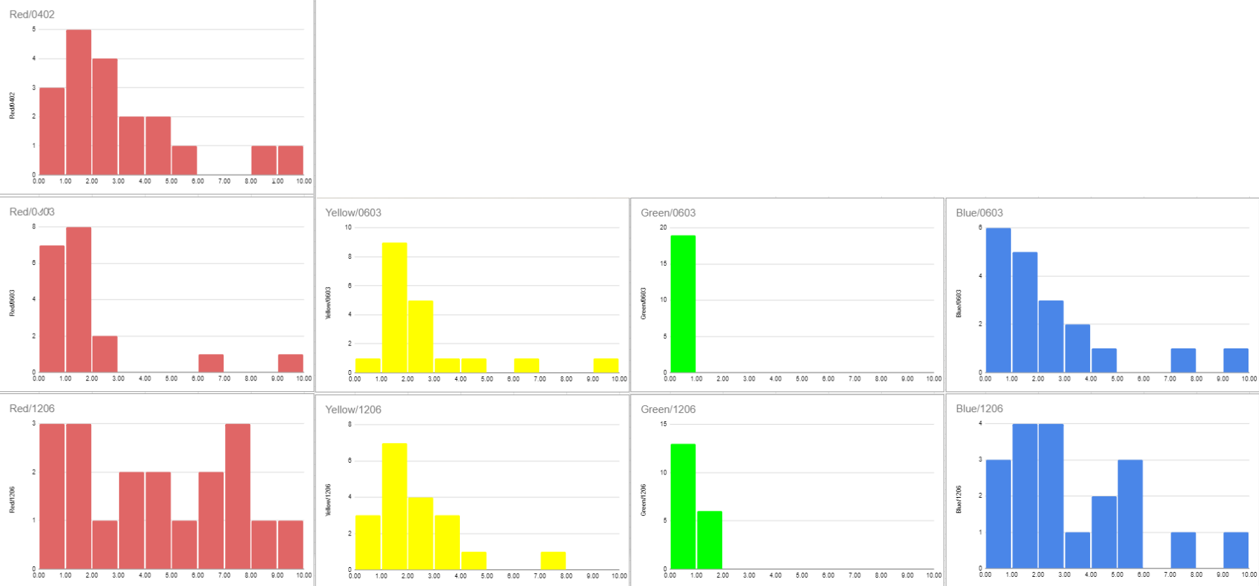
That's quite the spread! I then took the median resistance for each LED, then selected the nearest standard resistor value as our final LED resistors for 3.3V inputs.
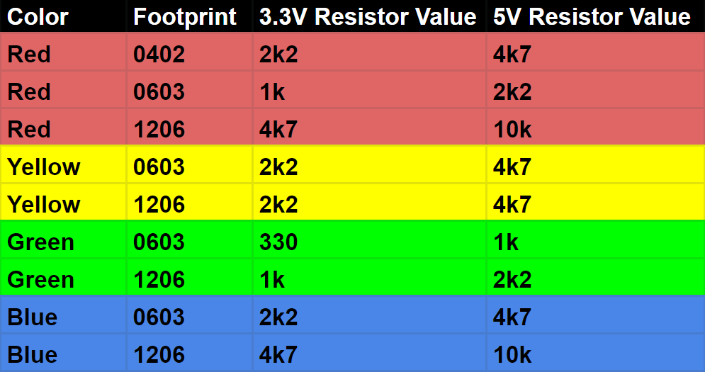
We also use 5V on a lot of products, so I added a column to the spreadsheet for that. I could have redone the survey at 5V, but I actually didn't need to! The brightness of each LED is determined by the amount of current flowing through it, which we just determined! So I can instead use Ohm's Law to calculate the resistor that results in the same current at a 5V input, and the LEDs will have the exact same brightness as before! I then tested it in person, and was pleased to see each LED at the same brightness as before. Now we finally have our perfect resistor values for each of our LEDs:
And how do they look? You tell me!
Customized Resistance - Even Brightness
Keep in mind, these resistor values only apply to the exact LEDs that we use! Your LEDs could require very different resistors, so you'll need to run your own tests if you want to achieve perfect brightness. But no need to worry about designing a custom PCB for testing, we've got you covered there!
Making it a product
The whole time I was designing this board, I had the goal of making this a product for users to easily test their own LEDs. I've done my best to make it as simple as possible and sell it as a kit, then users solder the boards themselves. The kit includes:
- 1x bare PCB
- 1x 10k potentiometer
- 1x 100 Ohm resistor
- 2x 5-pin headers
LEDs are not included with the kit, because the idea is for users to test out their own LEDs. The primary goal is to be a useful tool, but it could also serve as an educational resource for anyone new to electronics. It'd be a fun project for learning through-hole soldering, or even a place to practice surface mount soldering!
It also does a good job of demonstrating Ohm's Law, where lowering the resistance increases the current through a circuit. And this is a nonlinear relationship! For those of you familiar with Ohm's Law, you'll know the current is actually the inverse of the resistance. For some more visualization, I've plotted the resistance and the corresponding current:
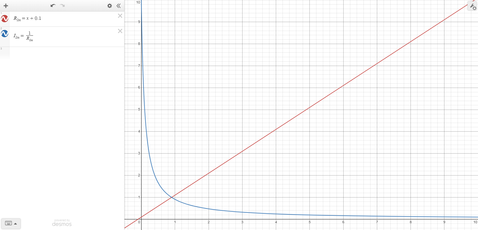
Resistance vs. Current
So, as the potentiometer knob is turned to the left, the current (and the LED brightness) shoots up very rapidly! I actually looked into using logarithmic potentiometers for this reason, but couldn't find one that I was happy with. If there's enough demand, we may look into sourcing a good logarithmic potentiometer for a future revision.
There were a handful of other things to clean up before releasing it into the wild. I originally made the board width exactly 0.6", which made for a pretty snug fit that could cause some boards to get jammed. So I reduced the board width by 0.015" on each side to give some wiggle room. We also decided to release it under SparkX, since this is more of an experimental product, so I had to change the logos from the first prototypes. Finally, we put a fun graphic on the back side, which is the standard LED symbol with way too many arrows coming out of it.

And that's that! If you're interested in having some of these to play with, you can pick them up below. Happy hacking!


Responding to your note about the highly non-linear relationship between the pot position and the current -- a way to address this would be to use a simple adjustable current-source circuit. This would entail adding one transistor, and a resistor, and possibly a zener diode. Then you would be able to get a linear relationship between knob and current. I realize that your end goal is to determine as suitable series resistor value, but I think it's more helpful to set a particular current with some repeatability. I think the user would end up having to measure the diode drop voltage, and current, anyway in order to adapt to their circuit, which might have a transistor in series, have the output resistance of an MCU GPIO, run off a different voltage and so on.
Your right, that would be a great way to fine tune the current for LEDs! You're also correct that the goal of this project was finding the best resistor value for each LED. All our products that include LEDs use a resistor in series to set the brightness, and I found a discrepancy between some of our products. So the main point of this project was really to get a more consistent experience across all our products by determining which resistor value to use in each case. I realized some people may want to do the same for their projects, so we just put the kit on our storefront rather than engineering a whole new solution that uses a constant current source.
Nice initiative Dryw! But there's something a bit off in the "5V resistor value" calculations, supposedly using Ohm's law. The forward voltage drops that you would have used to get those results don't entirely make sense. The numbers in that table indicate that you used 1.8V or 1.883V for Red; 1.804V for Yellow; 1.883 and 2.463V for Green, and ~1.8V for Blue.
But the forward drops for actual LEDs of different colors are different (as you noted in the article). In general, the colors at the red end of the spectrum have lower drops (say 1.8V than those at the blue end (2.6V). Those voltage drops vary a little with current, of course. But that doesn't explain how, for example, Red 0603 appears to have a drop of 1.883V an 1.42 mA, while Blue 0603 has a drop of 1.804V at 1.47mA.
Hi there!
For the sake of brevity, I didn't go into full detail about how exactly I calculated the 5V resistor values. But in short, I took the 3.3V LED circuits and measured the current (I_d) and diode voltage (V_d) drop for each LED. Then I calculated the ideal resistor value for 5V (R_5) with Ohm's Law like so:
R_5 = (5 - V_d) / I_d
For each LED, I found R_5 was roughly twice the value for R_3.3. I then just chose the closest standard resistor value so our manufacturing team doesn't have to worry about grabbing a weird assortment of resistors. I don't remember what I_d and V_d was for each LED, but the shorter wavelength LEDs did have larger V_d values. I just measured our 1206 blue LED, and I'm getting V_d = 2.5V, and I_d = 0.17mA when using a 4.7k resistor at 3.3V.
Hope this helps clarify!
Thanks for your reply! Your "roughly double" resistances for 5V vs 3.3V imply that the difference between LED drop and 3,3V is same as 3,3V to 5V, ie: 1.7V. Thus LED drop of 3.3-1.7 = 1.6V. However LED drop ranges far from this: more like 1.8V (red) to 2.5V (blue), and that matters a lot the closer your supply voltage gets to the LED drop voltage. So at 3.3V a blue LED series resistor sees only 3.3-2.5 = 0.8V, compared to red which sees 3.3-1.8=1.5V, almost double the blue case. For supply voltages (like 3.3V) that leave only a small dropper voltage, smaller series resistor is required, and must be set to a more precise ohm value to get same % error, but unfortunately your pot is not very capable of doing that (hence your suggestion about log pot). Additionally, with low dropper voltage, a higher percent of it is eaten by, eg. VCE of the transistor used to switch the LED, or series resistance of GPIO output. Hence my recommendation that users focus on understanding the actual current that gives the brightness they want, rather than trying to jump straight to a resistor.
That's true, the blue LEDs would ideally have a resistor closer to 4x than 2x when jumping from 3.3V to 5V. I don't remember my original reason for only going up 2x, but I think it was to not exceed 10k or something. Plus, the actual perceived brightness by the human eye isn't that much different, so the original goal of making our LEDs all have approximately the same brightness is still achieved.
Hi Dryw!
First, let me say that this is a really good idea! I wish I'd had this kit back in about 2013 when I was working at a small start-up and needed to figure out what resistor to use with the LEDs on a product I was designing. I ended up taking in a potentiometer from home, and with alligator clip leads, setting up to do what this board does. After asking several people to adjust it to "comfortable" brightness, I used a DMM to measure the resistance setting and selected the nearest SMD resistor in our stock to use. BTW, I'm really glad you included the "R+" and "R-" test points, so that with the power off it's easy to use a DMM to measure the resistance. Anyway, it seems a bit more practical, or at least more affordable, than using a Decade Resistance Box to test the LEDs!
FWIW, I've been "doing" electronics since the mid-1960s. In the mid-1970s, I was building a computer that included a "front panel" with a lot of LEDs -- around 30 or so. These were 5mm LEDs, and I'd bought them all at once (likely from Digi-Key). All of them had the same value series resistors. When I powered it up for the first time, I was dismayed that the brightness varied significantly -- with some LEDs being only about half as bright as others. I suspect that the manufacturing processes have improved and that LEDs from a given production lot are significantly more consistant, but it's probably best to be aware of this.
I learned some years later that Hewlett-Packard had to sort the four-digit LED displays for their calculators into several bins based on the brightness with a constant current. They were then careful that all of the units that went into a given calculator were from the same bin. I think that they also labeled each PCB with the bin number, just in case it ever needed to have one of the displays replaced.
I've done a couple of "wearable" designs using "NeoPixels". One of the things I quickly discovered was that they can be dazzlingly bright at "full tilt". Since I wanted to be able to wear them under a wide range of ambient light, I had to include a sensor for ambient light. Each of these has a microcomputer that controls the LEDs, and limits how bright they are based on the ambient light sensor. One is a "flashy Santa Hat" that has 11 LEDs scattered over it, and flashes them in various random patterns. It also has an accellerometer, so that when I shake my head it shifts patterns. The other wearable is a badge that flashes in Morse code "Hello my name is" followed by my name and my call sign. Both of these need to be able to be seen in both full sunlight, and not be overwhelming in a dimly lit restaurant.
One final thought: For indicators on circuits with microcomputers, using PWM to "tone down" the brightness of LEDs works well, which means the brightness can be controlled in software rather than having to change resistors. (You still have to have the resistors to limit the maximum current, but these can be chosen to provide current limits within the LED and microcomputer's operating limits.)
Thanks for your comment!
That's interesting to hear about how much variance LEDs used to have! I haven't actually tested how consistent our LEDs are between each other, that'd certainly be interesting to see! Although I've not observed any noticeable differences so far, so I'm guessing they're all pretty close to each other. Not enough to warrant us sorting our own LEDs :)
Oh yeah, I love addressable LEDs! I've used those NeoPixels (well, generic WS2812B strips, same part number) in lots of projects; I've currently got a strip under the cabinets in my kitchen making a big rainbow. I'm a sucker for fun colors, so that puts a big smile on my face!
I've been working on another personal project that I'm not ready to reveal to the world yet, but it has over 100 addressable LEDs, and is intended to live in a room. It does have an ambient light sensor for auto dimming, but even at minimum brightness, all those WS2812B LEDs can still light up a dark room. I discovered there's a WS2812C variant, which cuts the brightness by roughly 1/3 of the WS2812B. That helps, but there's still a lot of "stair-stepping" at low brightness. I'm working on a revision that will instead use the APA102C, which has 5 bits of global brightness per LED, which should help improve the low brightness performance while still being able to get super bright if needed.