More Python with the SparkFun LumiDrive!
Last week, we took a look at using the digital pins on our new LumiDrive LED Driver. This week, we'll play with the analog pins, and see if we can't put something together using both!

Last week, we started poking at SparkFun’s new LumiDrive LED Driver and played a little with the available digital pins broken out on the board. This week, we’ll take a look at the analog pins, play with them as inputs, and see if we can put something together using both digital and analog pins.
If you didn’t catch its release, let me introduce you to the SparkFun LuMini LED Driver. This board boasts a SAMD21G-AU microcontroller, to allow you to run Python, micropython, circuitpython, etc.
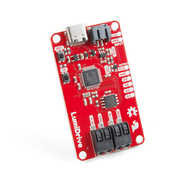
The SparkFun LumiDrive LED Driver. So powerful. So elegant. So red.
Let’s dig into analog input on the LumiDrive. The first thing we need to do is import the proper library. So just as we imported the digitalio library to read and control things connected to the digital pins, this time we’ll need to import the analogio library.
import analogio

# Then we impliment it with this line

analog_in = analogio.AnalogIn(board.A3)
There is another way to do this, which I didn't discuss last week. Unlike programming in Arduino, with Python (or microPython, or circuitPython) you don't need to import the entire library. If you are only using a single element from that library, it is also possible to do this:
from analogio import AnalogIn

# Now our sketch knows where AnalogIn came from, so
# we don't need to instruct it where to look. We can just use

analog_in = AnalogIn(board.A3)
High value potentiometers
If you're coming from the world of Arduino (or C), you would expect the analog value coming in from your potentiometer to be somewhere in the 0-1023 range – and you would be correct. However, things are a little different here. Your analog reading will fall within the range of 0-65535 (assuming 16-bit), so there's a much higher resolution.
Let's say we just want to see what value our trim pot is returning. Well first, of course, we need to attach our potentiometer. The hookup to the LumiDrive is simple, and just as you would expect. The outside legs of your potentiometer go to 3.3V and GND, with your center leg going to an analog pin. In this case I'm using A3.
Adding digital inputs to D8 and D9, and an analog input to A3
The pin.value call will return the raw data from your potentiometer, so with a simple sketch, we can see what our potentiometer is telling us.
import time
import board
import analogio

analog_in = analogio.AnalogIn(board.A3)

# Just read pin value
def get_pin_value(pin):
    return pin.value

while True:
    print (get_pin_value(analog_in))

time.sleep(0.05)
Once you've saved that sketch to your LumiDrive (as main.py or code.py), you can open up a serial terminal and you should see something like this.

Returned analog values from our potentiometer
Note! Even though Mu has its own serial window, the LumiDrive is not yet recognized by it, and will tell you something like:
Could not find an attached device.
Make sure the device is plugged into this computer.
Blah blah blah other important things.
For the time being, I'm simply using TeraTerm. You should have no problems with TeraTerm, CoolTerm or whatever your favorite terminal program happens to be.
Now you probably notice that the value never gets all the way down to zero. With a resolution of 65535 across its rotation, and the little bit of float, that is to be expected. There are ways to eliminate that, but that's an issue for a whole different post.
Variations
A potentiometer is a means to an end. That is, the values returned from a potentiometer are generally not as exciting as what we do with those values. Let's consider a few ideas.
Suppose we want to know the voltage going through our potentiometer. Since we're on a 3.3V setup, we'll want to take the returned value from our pot, multiply it by 3.3, and then divide it by the full range of our potentiometer. So it's not just a stream of numbers flying by, let's tell the casual observer what we're showing them. Try this.
import time
import board
import analogio

analog_in = analogio.AnalogIn(board.A3)

# Read pin value, calculate voltage on a 3.3V circuit
def get_voltage(pin):
    return (pin.value * 3.3) / 65535

while True:
    print ("Voltage is ", (get_voltage(analog_in)))

time.sleep(0.05)
Notice that to print a string and a variable together, you just need to add a comma between the two. Now what if instead of voltage, you want to change your RGB values? Just like with the voltage indicator, you simply need to multiply the pin value by the number of your desired range - in this case 256 - and then divide it by the potentiometer's resolution, 65535.
import time
import board
import analogio

analog_in = analogio.AnalogIn(board.A3)

# Map pin value to a scale of 0-255
def get_color(pin):
    return (pin.value * 256) / 65535

while True:
    print ("Color value is ", (get_color(analog_in)))

time.sleep(0.05)
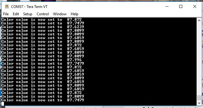
Returning a value in the range of 0-255. But come on, your LED isn't interested in (0, 255, 87.6239).
Of course, this gives us a float, when we really just want an integer. There are a few different ways to do this, and if you have a favorite, or you think my way is terrible, please let me know! For this example, I'm going to use the truncate command from the math library. Remember, we can either import the entire math library, of just the part we need.
import time
import board
import analogio
from math import trunc

analog_in = analogio.AnalogIn(board.A3)

# Map pin value to a scale of 0-255
def get_color(pin):  # Returning only integers this time
    return trunc((pin.value * 256) / 65535 ) #If we used 'import math', this would need to be return math.trunc()

while True:
    print ("Color value is ", (get_color(analog_in)))

time.sleep(0.05)
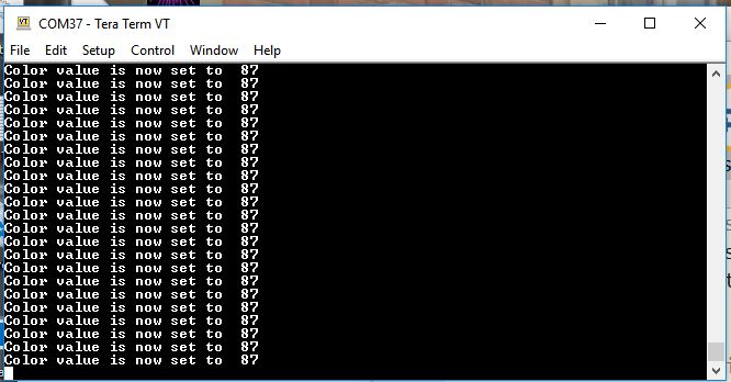
Ah, now that's more like it. Integers as far as the eye can see.
Off the screen and into the wild
We've only seen our values returned to us in our serial terminal window. Let's try to make something happen that doesn't need a computer screen to show results.
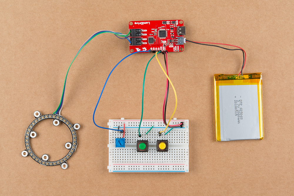
With our three digital inputs from last week, and our analog input from this week, let's try this. Since I just added components to last week's breadboard, I still have a yellow momentary button on D8, and a green momentary button on D9, and I'm just adding a potentiometer on A3. We'll use D6 as well, since it's there. I want to create a circuit that does the following:
If I push the green button, the LuMini 2-inch ring lights up green; push the yellow button, and the ring lights up yellow; push the on-board button, and the ring will light up red. I'm pretty sure that's close to what we did last week. But I also want it to blink, and I want to be able to control the speed of the blink with my potentiometer. Let's try this:
import adafruit_dotstar # The LED library
import math
import time
import board
import digitalio
import analogio

# Setting up the board's blue stat LED to blink
led = digitalio.DigitalInOut(board.D13)
led.direction = digitalio.Direction.OUTPUT

analog_in = analogio.AnalogIn(board.A3)

#Setting up the board's onboard button
button6 = digitalio.DigitalInOut(board.D6)
button6.direction = digitalio.Direction.INPUT
button6.pull = digitalio.Pull.UP

# Setting up the digital IO pins as input buttons
button8 = digitalio.DigitalInOut(board.D8)
button8.direction = digitalio.Direction.INPUT
button8.pull = digitalio.Pull.UP

button9 = digitalio.DigitalInOut(board.D9)
button9.direction = digitalio.Direction.INPUT
button9.pull = digitalio.Pull.UP


# These two variables should be adjusted to reflect the number of LEDs you have
# and how bright you want them.
num_pixels = 40 #The 3" ring has 60, the 2" ring has 40, the 1" ring has 20
brightness = 0.25 #Set between 0.0 and 1.0, but suggest never running at full brightness


# Some standard colors.
BLACK = (0, 0, 0)
RED = (255, 0, 0)
YELLOW = (255, 150, 0)
ORANGE = (255, 40, 0)
GREEN = (0, 255, 0)
TEAL = (0, 255, 120)
CYAN = (0, 255, 255)
BLUE = (0, 0, 255)
PURPLE = (180, 0, 255)
MAGENTA = (255, 0, 20)
WHITE = (255, 255, 255)

# This creates the instance of the DoTStar library.
pixels = adafruit_dotstar.DotStar(board.SCK, board.MOSI,
    num_pixels, brightness= brightness, auto_write=False)

# This function takes a color and a delay and fills the entire strand with that color.
# The delay is given in the case you use multiple color fills in a row.
def color_fill(color, wait):
    pixels.fill(color)
    pixels.show()
    time.sleep(wait)

# Here's where the action happens
while True:
    if not button8.value:
        led.value = True
        color_fill(YELLOW,0)
    elif not button9.value:
        led.value = True
        color_fill(GREEN,0)
    elif not button6.value:
        led.value = False
        color_fill(RED,0)
    else:
        led.value = False
        color_fill(BLACK,0)

    time.sleep((analog_in.value * 2) / 65535) #delay is determined by potentiometer reading

    color_fill(BLACK, 0)

    time.sleep((analog_in.value * 2) / 65535) #delay is determined by potentiometer reading
You'll notice a couple of things in this last example. The first is that while we defined functions to get our analog values in all of the previous examples, we did not in this one. To read our time.sleep variable, we read the analog_in.value within our while True loop. I did this because Python can't convert a function to a float, and the time.sleep call expects a float as its argument. Second, in getting the value for our time.sleep, I've multiplied our analog_in value by two before dividing it by 65535. This sets our maximum sleep time at two seconds, just like multiplying by 3.3 in the earlier example gave us our voltage range.
Wait, there's more!
But not this week. Again, this is mostly geared toward those among us (myself included) who haven't done much Python programming as it applies to the physical world. I'm sure there are better or more efficient ways to do exactly what I've just done, and since as long as I'm still breathing, I'm still learning, I'd love to see your suggestions and improvements in the comments.
I also recall saying last week that if all went well, I would try to use all of this in some sort of practical application or project. Well, things went well, but not quite that well. I have a head full of ideas as to how to use all of this in a build, but this week there just wasn't enough time, so that will be a post for another day.


this seems cool
Nice and informative writeup Rob, thanks! Having some of the basics explained like this, surely will safe me a lot of time ;-) And .. three cheers for using the MicroPython codebase (http://micropython.org) and not some other derivative python flavor ...