Enginursday: 3D-Printing Your Way to a Better Printer (Part 1)
Here's how I built a printer enclosure for my Taz 6.

I recently got a Lulzbot Taz 6 and like many first-time 3D printer owners, ran the thing for a week straight printing various and sundry items from Thingiverse.
After populating my pegboard with a few organization tools(the mason jar jumper holder and modular drawers are my favorites) and realizing while printing some pegboard compatible drawers that I'm having some serious adhesion and warping issues in my chilly basement, I decided it was time to create an enclosure to keep the heat in and prevent my ABS parts from cooling too quickly. I'd also like to avoid breathing some of the nasty fumes the printer can give off, so enclosing it is the first step to adding a ventilation fan to control both fumes as well as ambient air temperature.
This is a pretty big project, so I'm gonna split it into two parts, the first will be the construction of the enclosure, and the second will be the construction and addition of the optional vent fan and lighting. For part 1, I tried to design an enclosure that would use the smallest number of plexiglass pieces - my reference design is shown below. Note that this design can be used on many different Lulzbot printers by adjusting some of the dimensions (and probably some other ones, but I'm unsure).
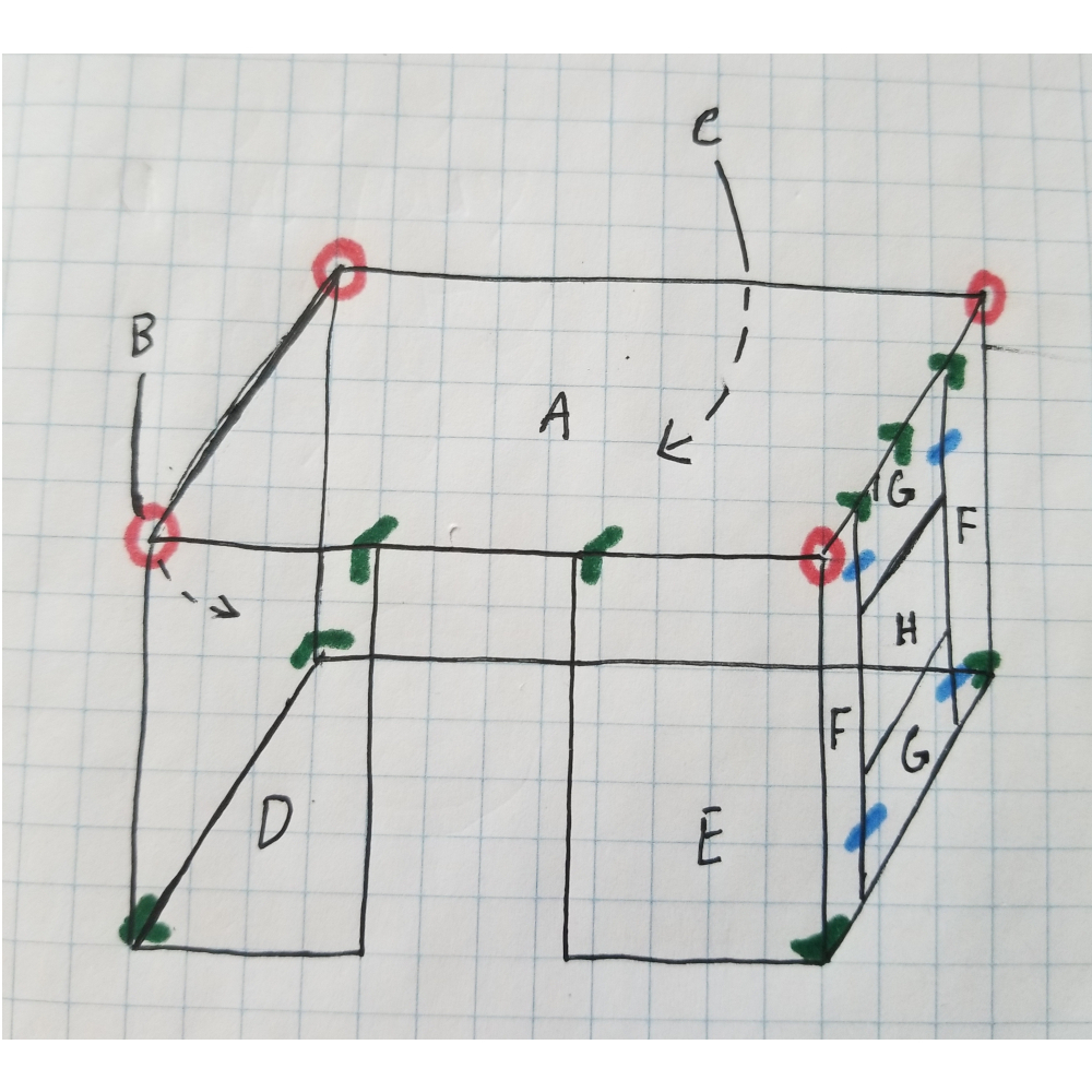
Reference Design
Once I had all of my measurements I checked the vast and ever-expanding interwebs for sizes of plexiglass that may be able to fit all of the different size pieces. I eventually settled on a 3 mm thick, 3'x6' chunk that seemed it would be able to fit all of my pieces, except for my door (H), which I wanted to cut from thinner, lighter plexiglass to ease the strain on my hinges. The dimensions in centimeters of all of the pieces are listed below.
- Back (B): 53*51.5
- Left-back (D): 23*51.5
- Left-front (E): 28*51.5
- Right (C): 69.5*51.5
- Top (A): 69.5*53
- Front: 2-10*51.5 (F, Left and right sides)
- 2-10*33 (G, Top and bottom)
- 32.5*31 (H, Door)
I cut all of the pieces (except the door, which I cut from an extra piece of lighter 1/16" plexiglass I had lying around) using the scoring tool that I bought right next to the plexiglass. I used the below layout to fit all of the pieces into the chunk as well as minimize the number of cuts I had to make.

Layout for Cutting Pieces
Cutting plexiglass can be tricky and tedious, so make sure to watch a Youtube video or two instead of learning the hard way from the back of the plastic-scoring knives package. The best tool you have here is patience.
Make sure you score a great deal of the way through the plastic (at least halfway) before trying to break it to ensure you get clean edges. Piece D was a little tricky as I had to cut away 2 cm only going up half of the piece to allow for the Taz 6's wiring harness. To accomplish this, I added some scores at the proper places and broke chunks off with a hammer. These are the times when I wish I had a big old tabletop CNC, but if I never had to do anything manually, I wouldn't appreciate my robotic servants so much.
While you're cutting plexiglass, it's a good idea to also start printing the brackets that will hold the whole thing together. The individual .stl files are in a .zip below, but you'll still need to slice them yourself.
I used the following numbers of pieces, but you can always add another set of edge pieces at the midpoint of any of the box edges to add structural support if you please. Also, you can use these pieces for any sort of 3 mm thick plexiglass box. I printed all Corner, Edge, Flat and Hinge pieces at 100 percent infill, but the rest of the pieces can be done at a standard 20 percent. I also used 60 4-40 1/4" screws for the brackets, nine 4-40 3/4" screws for the filament port and stand, and three 3/16" magnet rings to hold the door closed.
- 4 - Corner
- 9 - Edge
- 5 - Flat
- 2 - Male Hinge
- 2 - Female Hinge
- 1 - Knob Rest
- 1 - Knob
- 1 - Port
- 1 - Stand
- 1 - Hole Guide
To finish these prints (I rarely fine tune hole sizes on one-off things like this, instead opting for a drill bit to do my fine tuning), go ahead and bore out all of the holes with a 7/64" drill bit. You may also need to file the peg on the male hinge as well as drill out the hole on the female hinge to make them fit properly. Make sure the hinges fit together and slide smoothly before attaching them to any plexiglass.
Use the hole guide print to drill pilot holes in the appropriate corners of pieces A, B, C, D, E and F (anything that attaches to the top piece's corners). If you're confused, refer to the reference drawing, which has these corners circled in red. Once you've drilled your pilot holes, attach the four corner brackets to piece A, then flip piece A on its back so that the brackets stick up in the air to allow for easy attachment of pieces B, C, D, E and the two F pieces.
Next, attach the edge brackets in the proper locations (shown in green on the reference design) by first drilling one hole, attaching the bracket with a screw, then drilling and attaching the other side of the bracket. Finally, use the four flat bracket pieces (shown in blue on the reference design) to attach the G pieces to the F pieces, again drilling and attaching one side, then drilling and attaching the other.
Now, we need to attach the male hinges to piece H. Make sure they both hang off the left side of piece H the same amount so that they swing on the same axis. From here, slip the female hinges onto the male hinges and use them as guides to drill pilot holes for their screws on piece F. Now you can drill a hole pretty much anywhere on the right side (just make sure it's close enough to the edge that the center can be reached by a Flat piece) and attach the knob with a 3/4" screw from the backside. You can now glue the other magnet into the knob rest and attach it opposite your knob on piece F. Line things up so that the magnet aligns with the screw that holds the knob in place.
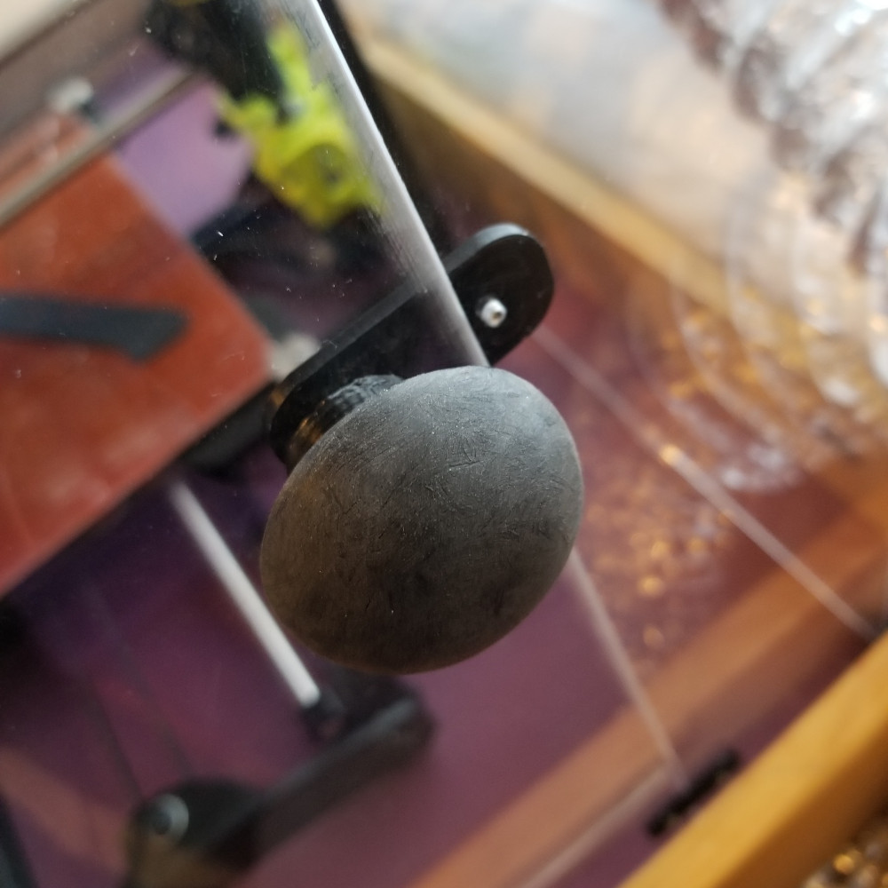
Knob
Now is a good time to slide the assembly over the printer so we know where to place our filament port and stand. For these, I simply tried to center them to the best of my ability over the printer head then drilled and attached them with 3/4" screws. The filament port needs a pilot hole with a 3/8" drill bit, then you can insert the port and use it to drill out the pilot holes on the sides to attach it with 3/4" screws. Once again make sure to drill and attach one hole before drilling and attaching the second hole. My one regret here was not making the filament stand and port one single piece, so if you're up for a little design, this is the piece that needs improvement.
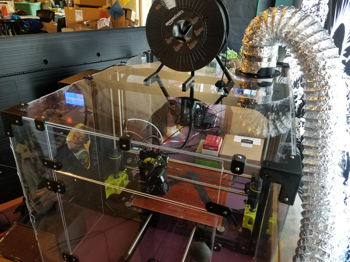
Now that your printer enclosure is assembled, time to rip off that protective plastic covering and marvel at your pretty new box. This is the end of part 1, stick around for part 2, where I'll add lighting and a ventilation system (which you can see is already in progress) to extract fumes.


Do you have a link for the pegboard modules you've found useful? A fellow maker with 2.5 walls of his shop covered in pegboard is interested. :-)
Sure! Go ahead and click the text where I say "Few organization tools" and it'll download a zip of everything I've found moderately useful.