MicroMod-Controlled UV Lightbox for Exposing Blueprints and Burning Silkscreens
With a strip of solderable UV LED tape, a cheap poster frame, some scrap wood and a few Qwiic-enabled breakouts, I built this simple tabletop UV lightbox with a countdown exposure timer.

Printmaking is a personal interest of mine, and lately I’ve been feeling the urge to jump back into silkscreening t-shirts and art prints. Light-sensitive emulsions are used pretty commonly across fine art printmaking and photography techniques, and if you’ve ever made your own PCB, you might have used a UV-sensitive resist to etch the circuit. Cyanotypes (aka blueprints) have historically been used both by artists and draftsmen, and can easily be exposed in direct sunlight if you have that available. If not, you might want to build a UV lightbox!
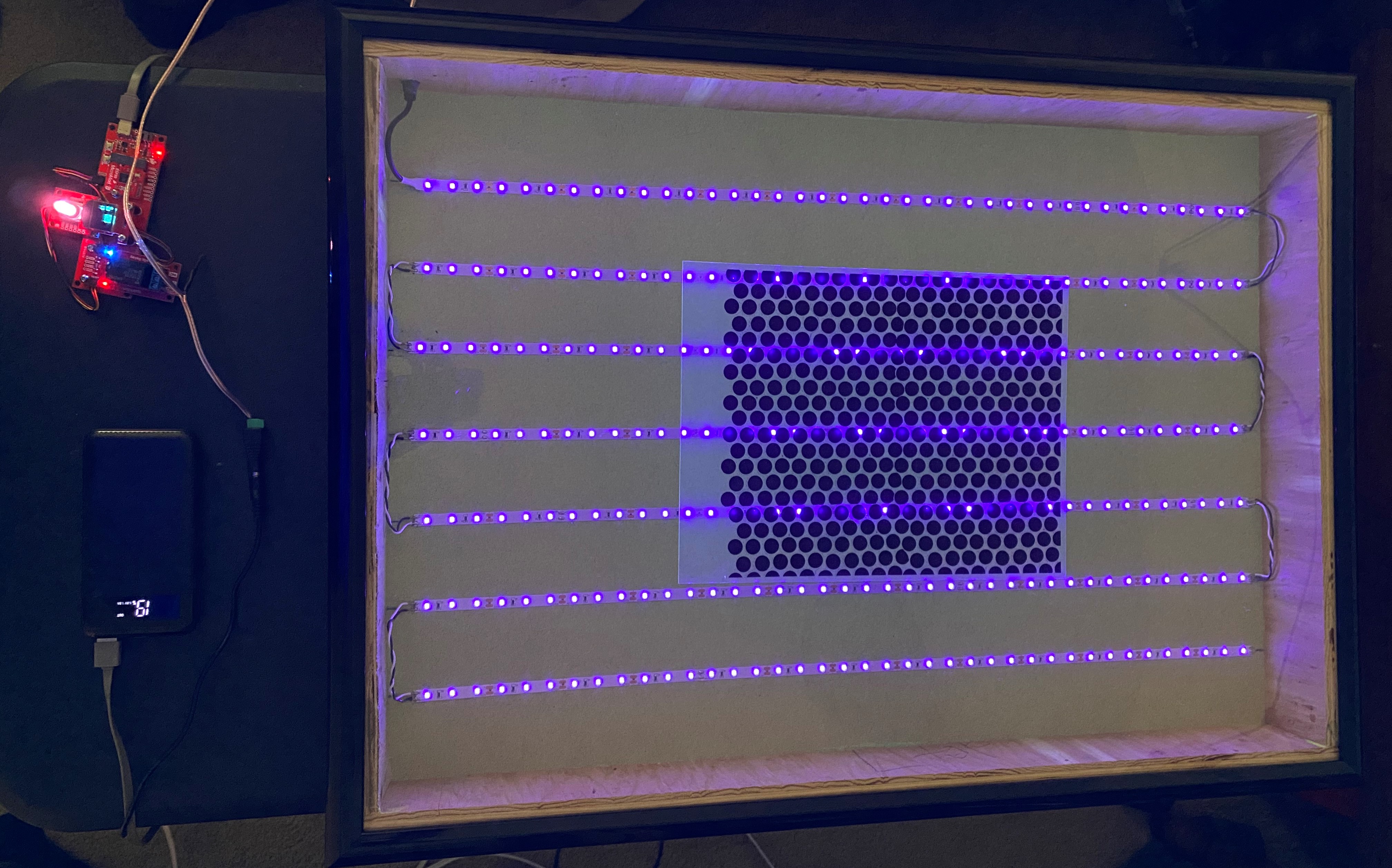
My tabletop UV exposure unit
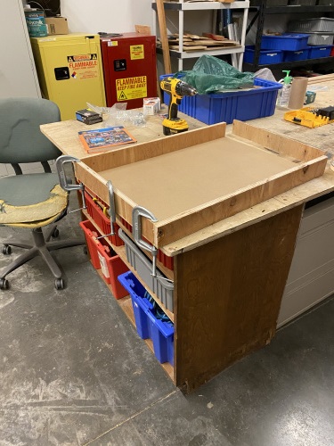
The lightbox itself is made out of a large poster frame, some scrap wood, and some UV-LED tape. To build the box, I cut some scrap plywood down to about 2.5 inches in width, and used wood glue and screws to adhere the walls of the box to the fiberboard backing board of the poster frame.
Once the glue was dry, I cut my LED tape into lengthwise strips and taped them into place, and soldered jumper wires to connect everything up. Finally, I drilled a hole slightly larger than the LED tape’s included barrel jack connector, and “mounted” it in the side of the box with a large glob of hot glue. After testing out my circuit, I placed the clear plastic and black frame on top of the box, and added some rubber feet to the underside to avoid scratching surfaces, thus completing the actual lightbox component of the project. The clear plastic is glued into the black poster frame, and it’s pretty flimsy, but it should do the trick until I can find some sturdier plexiglass to replace it. This lightbox can be used standalone without the MicroMod timer by simply plugging in the included wall wart and connecting the barrel jacks.
For my purposes, the MicroMod timer definitely makes exposures more accurate. To make yours, you’ll need the parts in this wishlist:
Our new MicroMod Qwiic Carrier boards are some of my favorite products because they allow you to assemble standalone devices without annoying headers, breadboards, protoboards, jumper wires, or other mounting devices. Not to mention that if you decide to change microprocessors, you don’t have to perform surgery on your project anymore - just unscrew and swap out the MicroMod processors.
To assemble the controller, I first inserted the ESP32 processor and connected my Qwiic Twist to the carrier so that its unused mounting holes overhang the “bottom” side of the carrier, using longer screws and some extra hardware to create extra supports for it. Next, I used a couple of nylon standoffs and some longer screws to mount my OLED display above the rotary encoder. This is a bit of a tricky fit but it works. Then I used the remaining mounting space on the carrier board to support my Qwiic Single Relay and added some nylon standoffs to the carrier board to allow it to sit flush on the table.
The final step in assembling the timer is to connect everything with Qwiic cables, and wire up the male and female barrel jacks to the relay in the “normally open” (NO) and COM screw terminals. Make sure to keep the polarity consistent between the male and female barrel jacks! The assembled controller should look something like this:
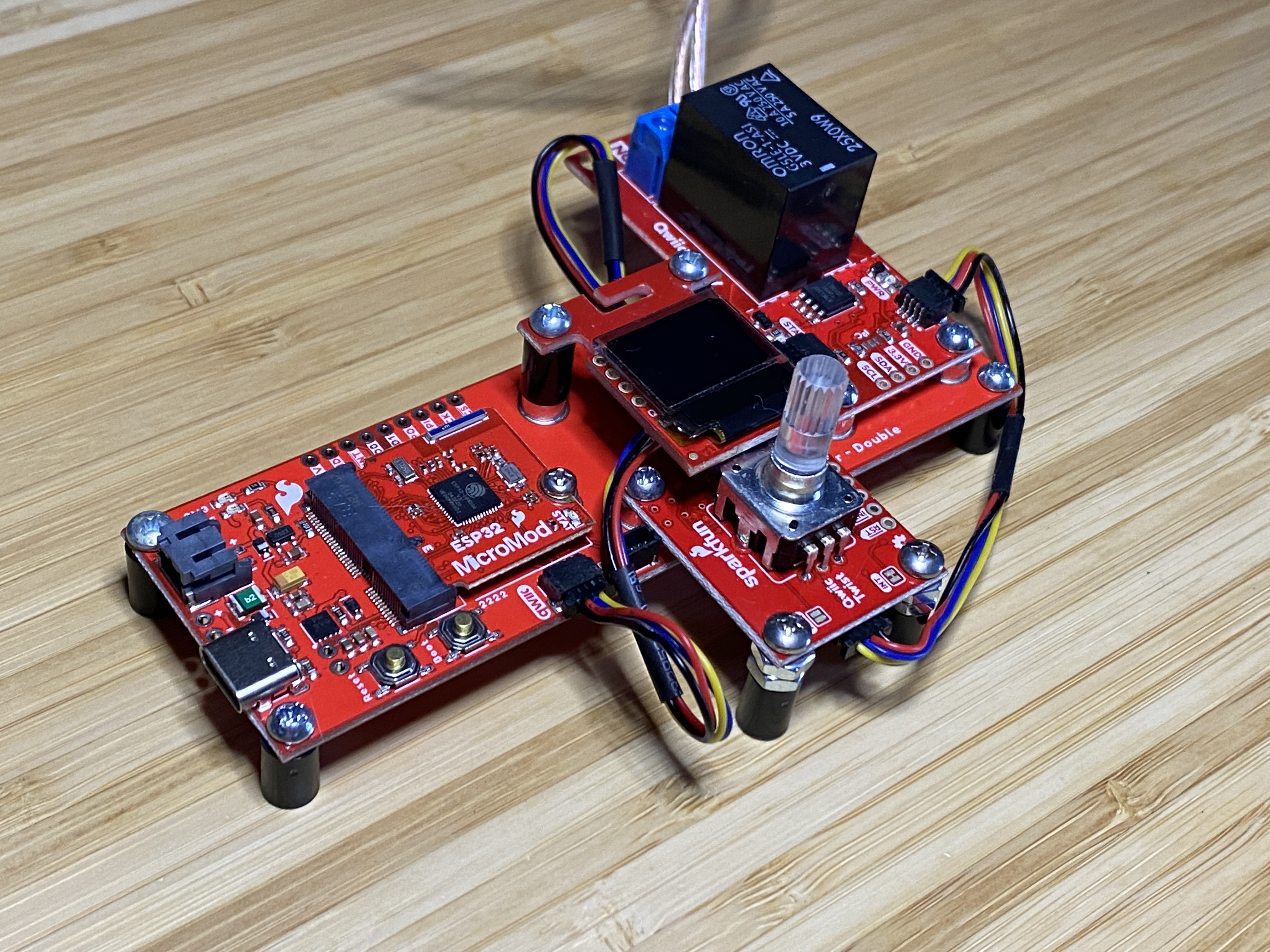
The fully assembled MicroMod Timer
Given that I already followed the setup for the ESP32 MicroMod Processor and various Qwiic breakouts (see the hookup guides), I was ready to upload my sketch and test everything out. The sketch below allows the user to select how many minutes and seconds to turn on the relay, and thus the UV lightbox.
/******************************************************************************
Micromod Timer Sketch
******************************************************************************/
#include <Wire.h>
#include <SFE_MicroOLED.h>
#include "SparkFun_Qwiic_Twist_Arduino_Library.h"
#include "SparkFun_Qwiic_Relay.h"

#define RELAY_ADDR 0x18

Qwiic_Relay relay(RELAY_ADDR);

TWIST twist;

#define PIN_RESET 9
#define DC_JUMPER 1

MicroOLED oled(PIN_RESET, DC_JUMPER);

void setup()
{
  delay(100);
  Wire.begin();

  relay.begin();

  twist.begin();
  twist.setLimit(59);

  oled.begin();
  oled.clear(ALL);
  oled.display();
  delay(1000);
  oled.clear(PAGE);
  drawPrompt();
}
void drawPrompt(){
  oled.setCursor(24,0);
  oled.print("MINS");
  oled.setCursor(24,8);
  oled.print("SECS");
}
int numSelector(int lnToPrint){
  int lnVal = lnToPrint;
  int cursorYval = ((lnVal-1)*8);
  int returnNum;
  while (twist.isClicked() == false){
    int cursorNum = twist.getCount();
    if (cursorNum < 10){
    oled.setCursor(0, cursorYval);
    oled.print("   ");
    oled.setCursor(0,cursorYval);
    oled.print(cursorNum);
    oled.display();
    returnNum = cursorNum;
    delay(50);
  }else{
    oled.setCursor(0, cursorYval);
    oled.print(cursorNum);
    oled.display();
    returnNum = cursorNum;
    delay(50);
  }
  }
  return returnNum;
  }
void loop(){
  //drawPrompt();
  twist.clearInterrupts();
  int selectedMins = numSelector(1);
  oled.setCursor(0,0);
  oled.print(selectedMins);
  oled.display();
  twist.clearInterrupts();
  int selectedSecs = numSelector(2);
  oled.setCursor(0,8);
  oled.print(selectedSecs);
  oled.display();
  twist.clearInterrupts();

  int totalSecs = ((selectedMins *60)+selectedSecs);
  int remainingSecs;

  relay.turnRelayOn();

  for (int i=0; i<=totalSecs; i++){
    oled.setCursor(0,24);
    remainingSecs = (totalSecs-i);
    oled.print("           ");
    oled.display();
    oled.setCursor(0,24);
    oled.print(remainingSecs);
    oled.display();
    delay(1000);
  }
  relay.turnRelayOff();
  delay(100);
}
After uploading, I connected my lightbox assembly to the controller by plugging the LED strip’s 12 V power supply into the controller’s female barrel jack, and then plugging the controller’s male barrel jack into the lightbox. The controller itself is simply powered by a USB power bank and the onboard USB-C connector. To set the exposure timer, turn the rotary knob until the desired number of minutes is reached, then click the button to confirm your selection and repeat the process for the number of seconds. Once you click the button of the rotary knob a second time, selecting the desired seconds, the relay will click on and the total remaining seconds will be counted down on the OLED display.
Counting down!
To test my setup, I first attempted to expose a test pattern on a silkscreen, hoping to jump right into making some shirts. Unfortunately, I think I underexposed my emulsion because my test pattern didn’t hold up when I tried to wash out the screen in my shower. It seemed to be working at first! As of writing, I haven’t had time to attempt to burn another silkscreen, but I’m confident that if I just extend the exposure time from 10 minutes to maybe 20 or 30, I’d get reliable results. For those wondering, I’m using Ecotex LED Emulsion, which is supposed to be calibrated specifically for LED exposure units. I checked to make sure that the wavelength of my UV LEDs would affect the emulsion, so theoretically everything should work.
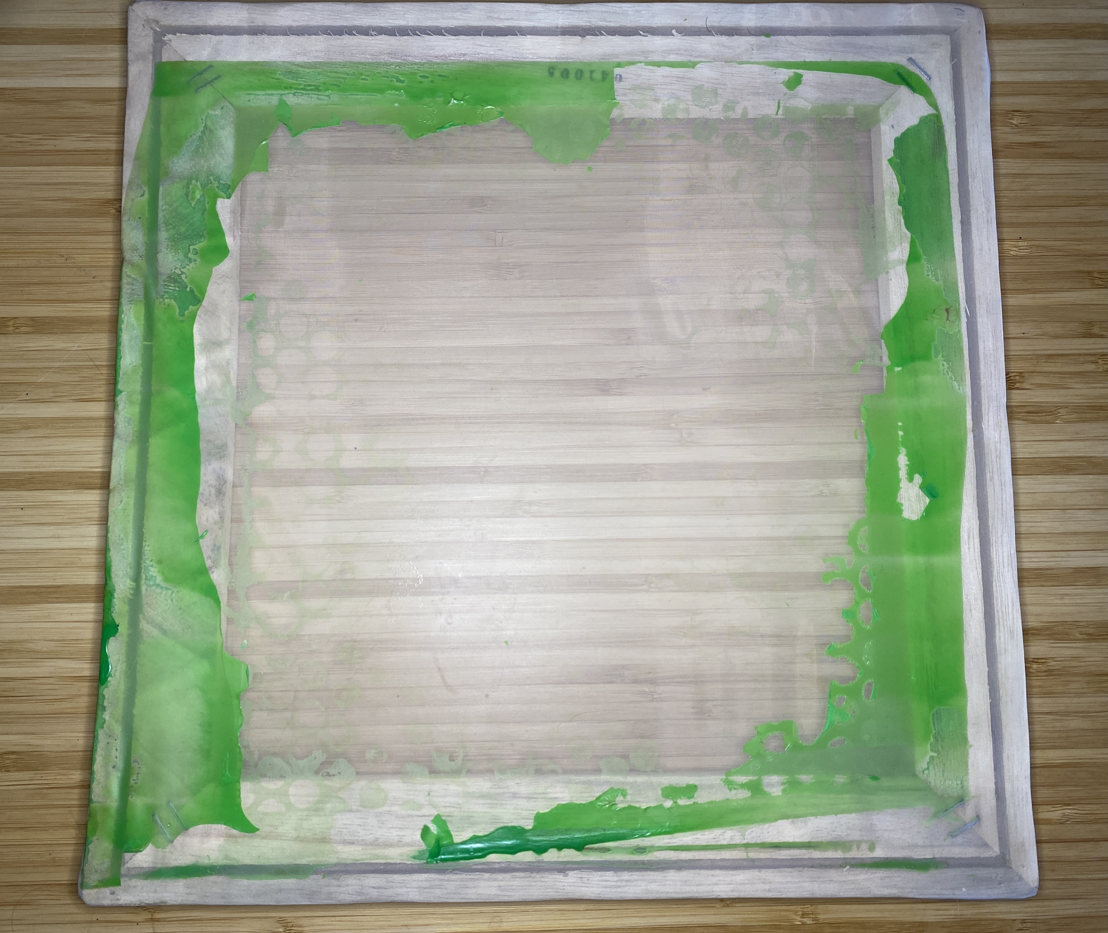
If at first you don't succeed...
Thankfully, I did have an alternative way to test out the lightbox - blueprint paper! Lately in my art-making, I’ve been obsessed with cyanotype prints. Although kits are available to mix your own chemicals and treat your own paper, I’m a big fan of the pre-treated paper from SunPrint kits. By playing around with the timing, you can actually achieve a range of blue tones from light to almost black. After exposing the paper, the print is revealed by submerging the paper in water, washing away the unexposed areas that were protected by the transparencies. I find that about nine minutes is perfect for dark-but-not-too-dark prints. Results below!
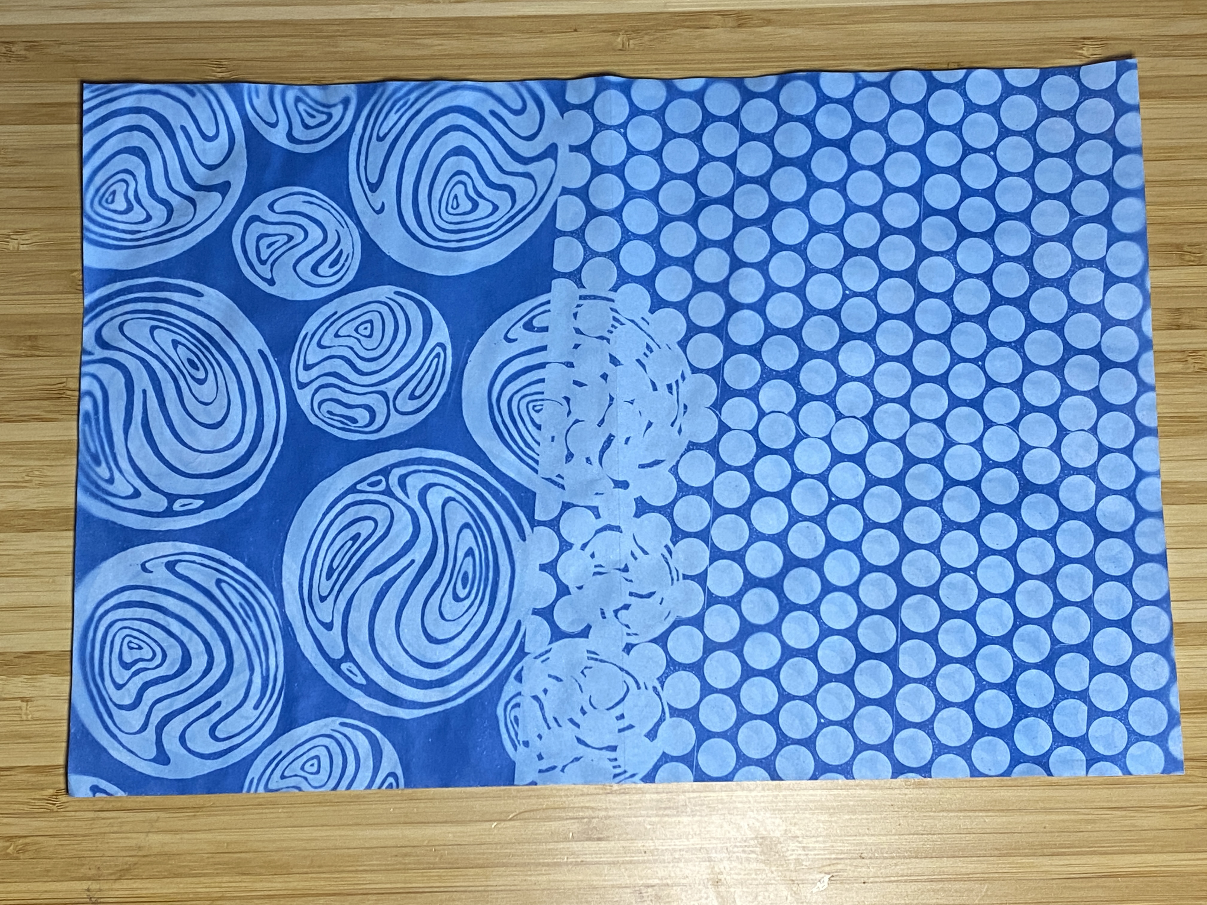
...give up and do something else


I remember back in the 1970s building a "UV eraser" to erase EPROMs (Erasable Programmable Read Only Memory devices, for the youngsters -- predecessors of "flash" memory used with most of today's processors). It consisted of a UV "sterilization lamp" (from the local appliance repair shop) mounted inside a 3 pound coffee can, a switch, a 25W incandessant bulb mounted on the outside of the can and in series with the switch and UV bulb to act as a "ballast", as well as a "power indicator", and, of course, a power cord. Timing was done courtesy the sweep second hand on a clock or watch, and didn't need to be that accurate.
An earlier project had been a timer for my enlarger -- based on a 555 timer. Unfortunately not very accurate... but the enlarger wasn't very good either. (For the kids, an "enlarger" was used to make large photographic prints from small negatives. The most basic ones were just a lamp, a "carrier" for the negative, and a lens to focus the image on the blank paper which was coated with a silver-based emulsion that would then be put through a "developer" bath, usually a "stop bath", and then a "fixer" bath to remove the unexposed silver chemicals.)
I'm sure your project is far, far more accurate than mine from about a half century ago! Anyway, thanks for sharing!
P.S. Mine were back in the days when the most common "human interface" for computers was punched (paper) cards.