Qwiic Crane Part I: How to Make a 3D Printed Toy Crane
How I used Qwiic breakouts, the MicroMod system, and Tinkercad to make a joystick-controlled toy crane.

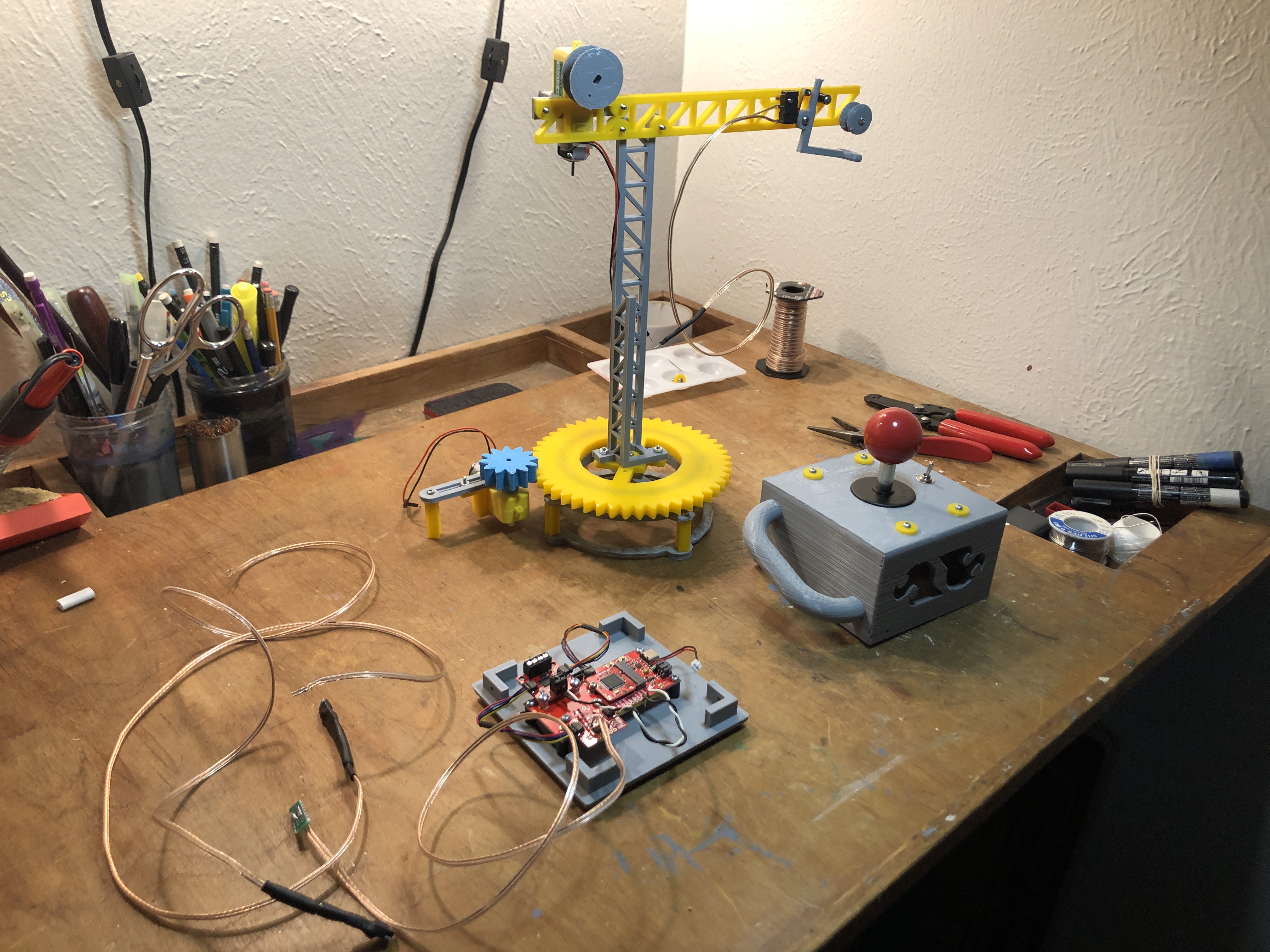
I've always been a little obsessed with construction toys. I still have my large plastic tote of LEGO bricks that I play with periodically, and I'm always on the lookout for vintage Erector sets at flea markets. Typically, my tinkering always turns toward crane construction, an interest that began way back when the History Channel would run days-long marathons of "How It's Made" and "Modern Marvels" (my how things have changed). In my opinion, every good toy construction system should have a crane set, so I decided to design a 3D-printable crane kit in Tinkercad specifically for SparkFun's own MicroMod and Qwiic systems. MicroMod and Qwiic aren't toys, strictly speaking, but they do imitate the plug-and-play simplicity of LEGO bricks, so trial-and-error style tinkering and DIY-ing feels like playtime. Below are build instructions, and links to all the 3D files and parts needed to build your own! Happy tinkering!
- 24 - ½” 4-40 Phillips head screws
- 10 - ¾” 4-40 Phillips head screws
- 4 - ¼” 4-40 Phillips head screws
- 12 - 4-40 nuts
- 1 - SPDT toggle switch
- 1 - SPDT microswitch (roller)
- 1 - Arcade Joystick
- 5 - 4-40 nylon standoffs
- Wire
- 1 - 1” proto board
- 3 - 2 pin headers right angle
- 1 - 2 pin JST wire/connector
- 5 - 100mm Qwiic Cable
- 1 - 200mm Qwiic Cable
- 1 - MicroMod Qwiic Carrier - Single
- 1 - SAMD51 MicroMod processor
- 1 - Qwiic Motor Driver
- 1 - Qwiic Button Breakout (no button)
- 4 - Qwiic Switch (SPX)
- 1 - Lithium Ion Battery - 1250mAh (IEC62133 Certified)
- 1 - Hobby Gearmotor - 140 RPM (pair)
- 22 - 15mm marbles or ball bearings (NOT SOLD BY SPARKFUN)
Once you have collected all the parts you need and printed out the Qwiic Crane Kit from Tinkercad, you're ready to start assembly! First up is the Crane's rotating base. This sub-assebmly features the only parts you'll need to source yourself: about 22 15-millimeter diameter ball bearings or marbles. For starters, the bottom side of the bearing assembly is constructed using nine of the 1/2" 4-40 screws to attach the five rectangular standoffs and base piece as shown below.
Bearing base assembly
Next, carefully insert a 4-40 hex nut into the slot on the underside one of the hobby motor mounts, and carefully thread another 1/2" screw through the slot and nut as show below. This screw will be inserted into one of the hobby motor's mounting holes to prevent it from sliding laterally out of the motor mount.
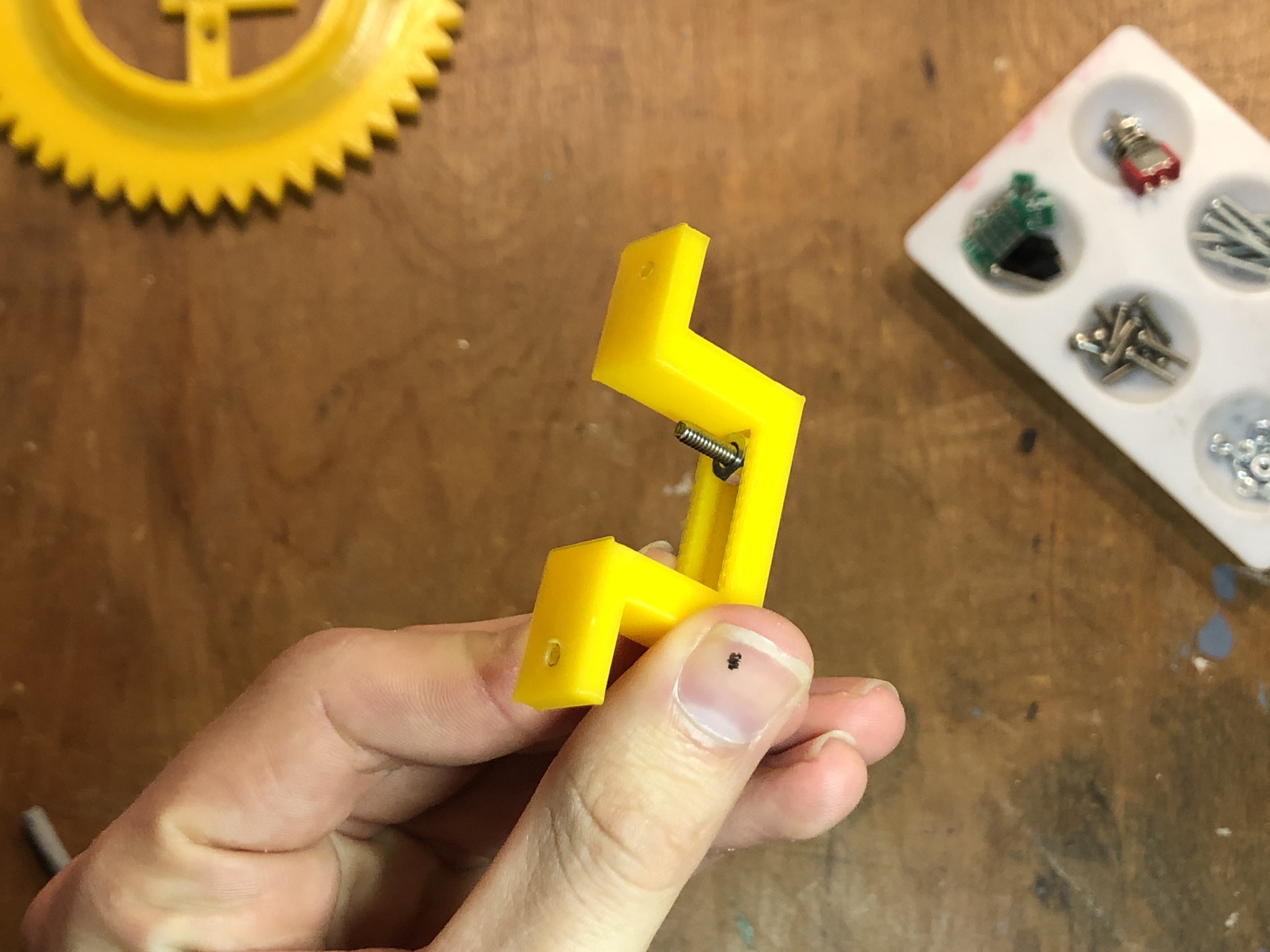
The hobby motor mount features a groove to fit a 4-40 captive nut
Attach the mount to the motor as shown. Note that one side of the hobby motor has a small protrusion that will get in the way if is not facing outward.

Attach the motor with the little bump facing outward as shown
The motor assembly can now be attached to the bearing base assembly by slotting a couple nuts into the groove and tightening everything together with a couple more 1/2" screws, which will protrude upward slightly. Make sure the spindle of the motor is oriented as shown in the picture below so that the drive gear will properly mesh with the bearing gear.
Attach the motor assembly to the base with two more captive nuts.
Now it's time so add our ball bearings or marbles to the channel of the base. There will probably be some wiggle room, but that's ok.

Fill the channel in the base with 15mm diameter marbles
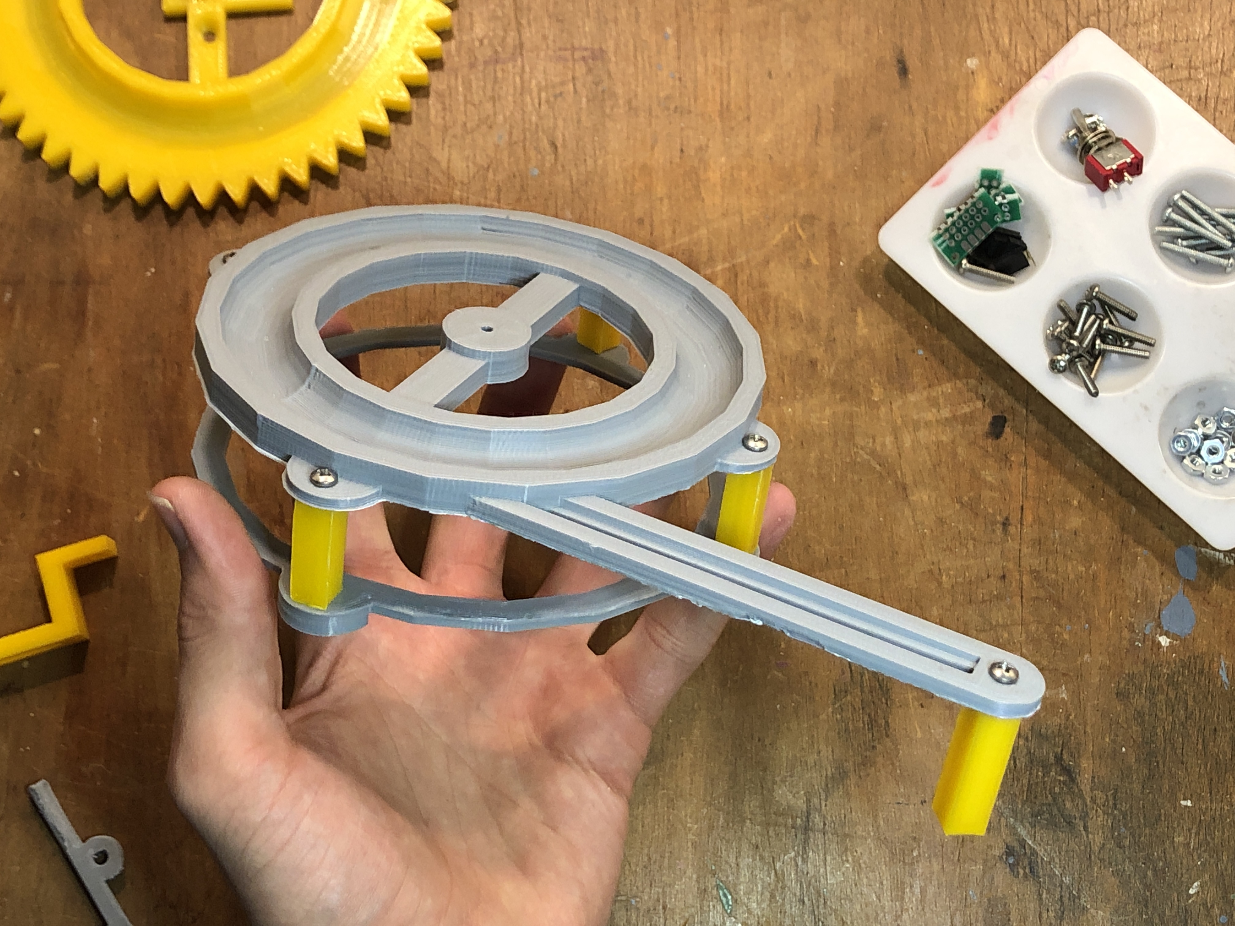
To attach the top gear of the bearing assembly, we need to thread a 3/4" 4-40 screw through one of the 3D-printed washers like so:
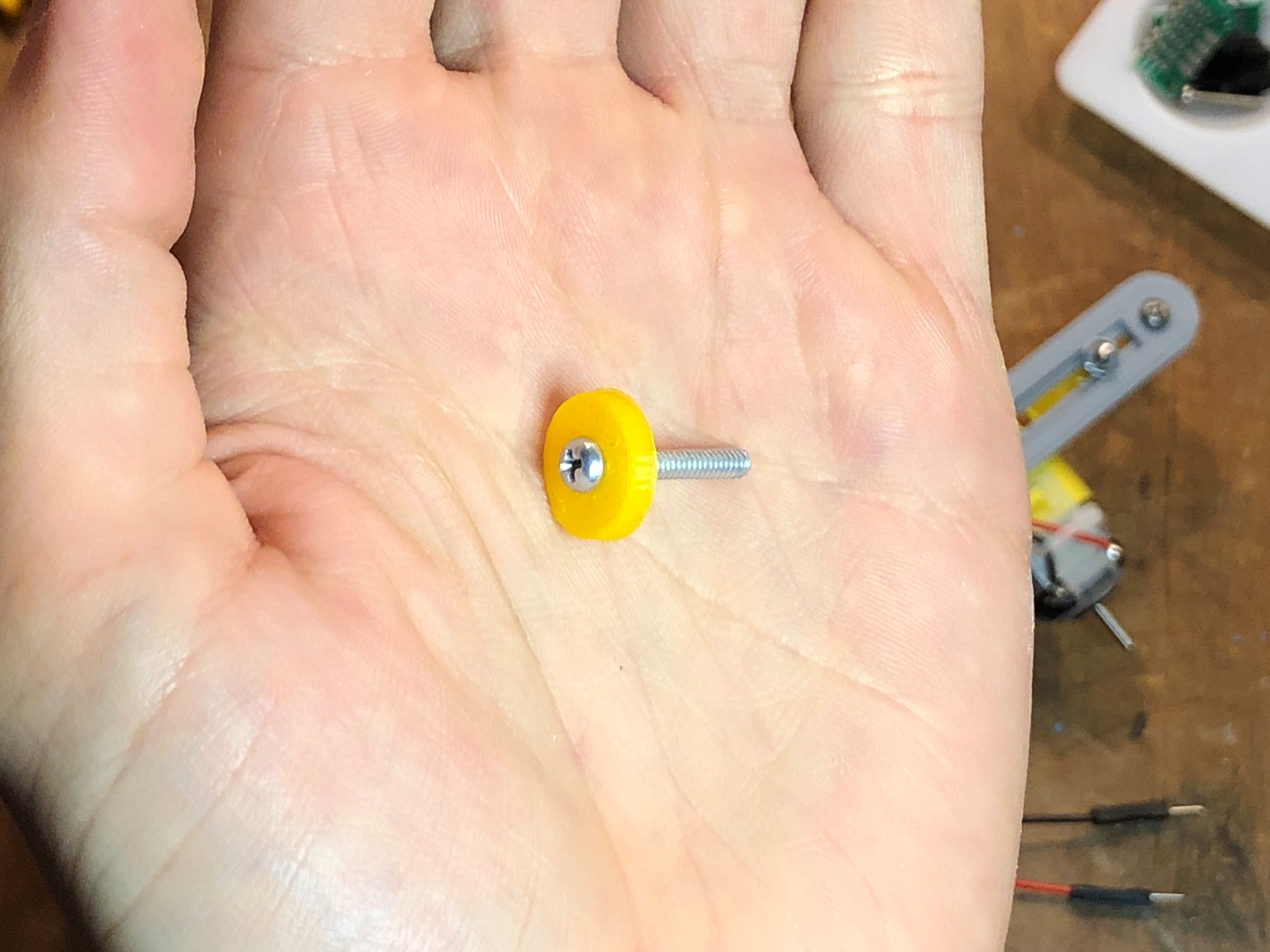
Thread a 3/4" 4-40 machine screw onto a plastic washer
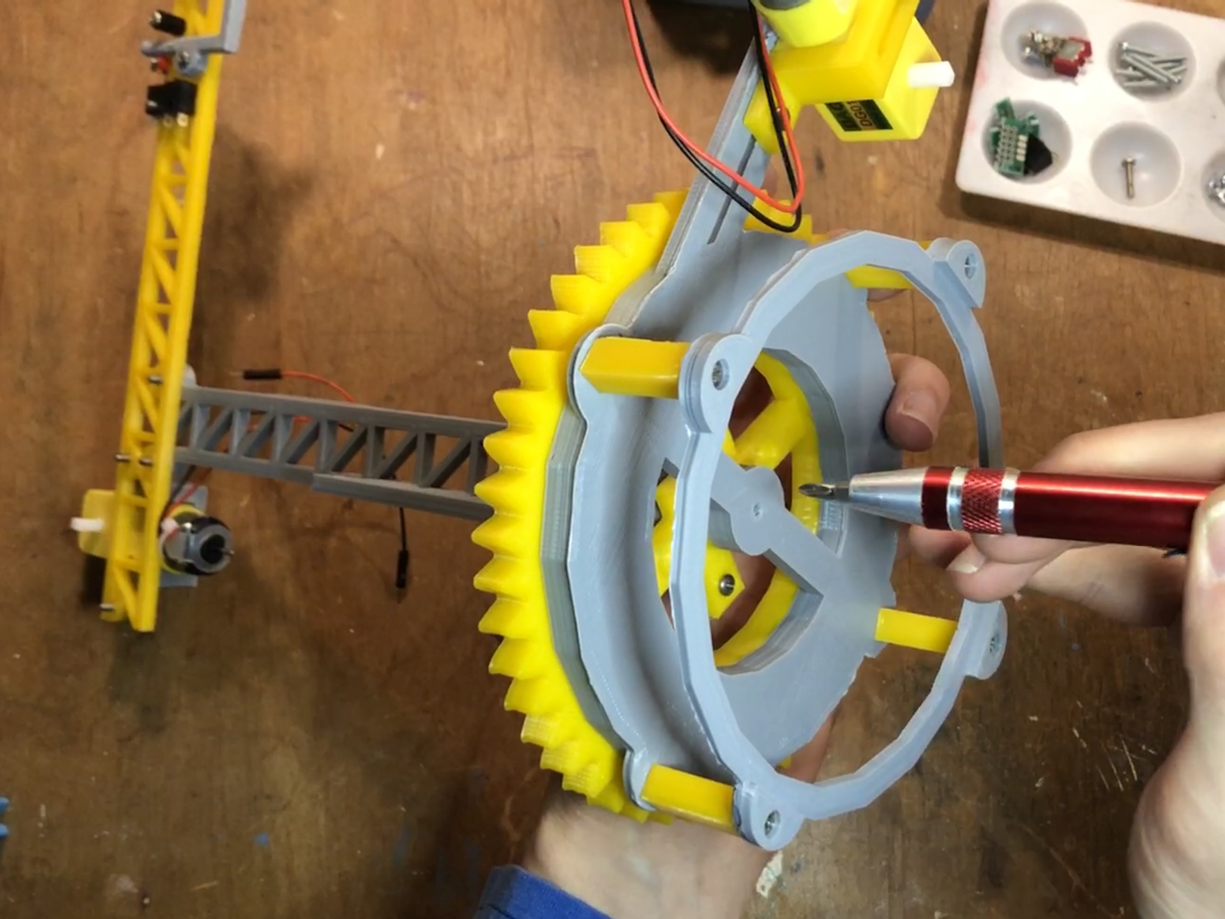
Next, insert that screw and washer through the center hole of the top gear, and screw it firmly into the center hole of the bearing base assembly. Don't tighten the screw too much, the gear should be held steadily in place, but still rotate on the ball bearings pretty easily. This part of the crane is finished for now, so we can set it aside and put together the crane tower and boom.
Use the screw and washer to secure the top side of the bearing to the base
First, grab the boom arm and hoist limit switch parts, and prepare the hoist limit switch as shown. You'll need one nylon standoff, the roller microswitch, and a few 4-40 screws.
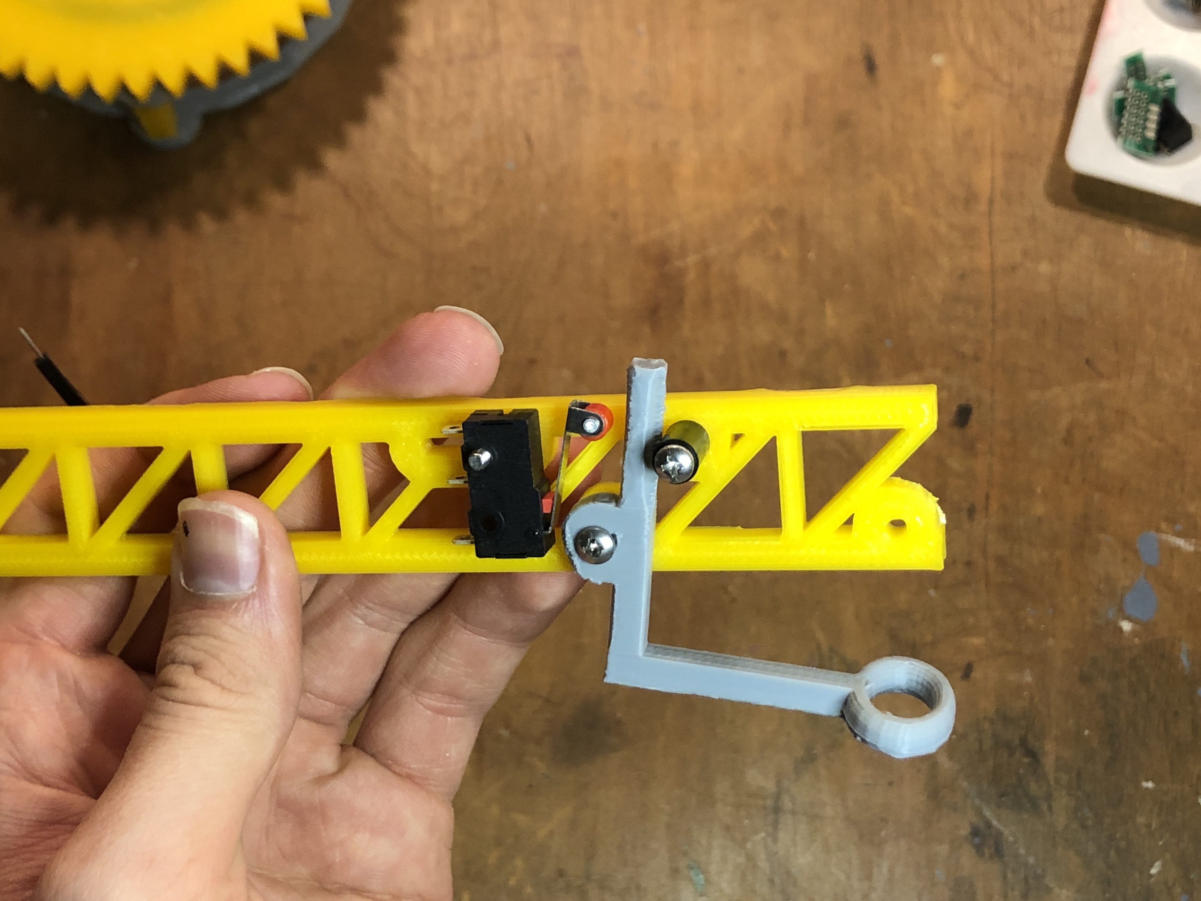
Winch limit switch assembly
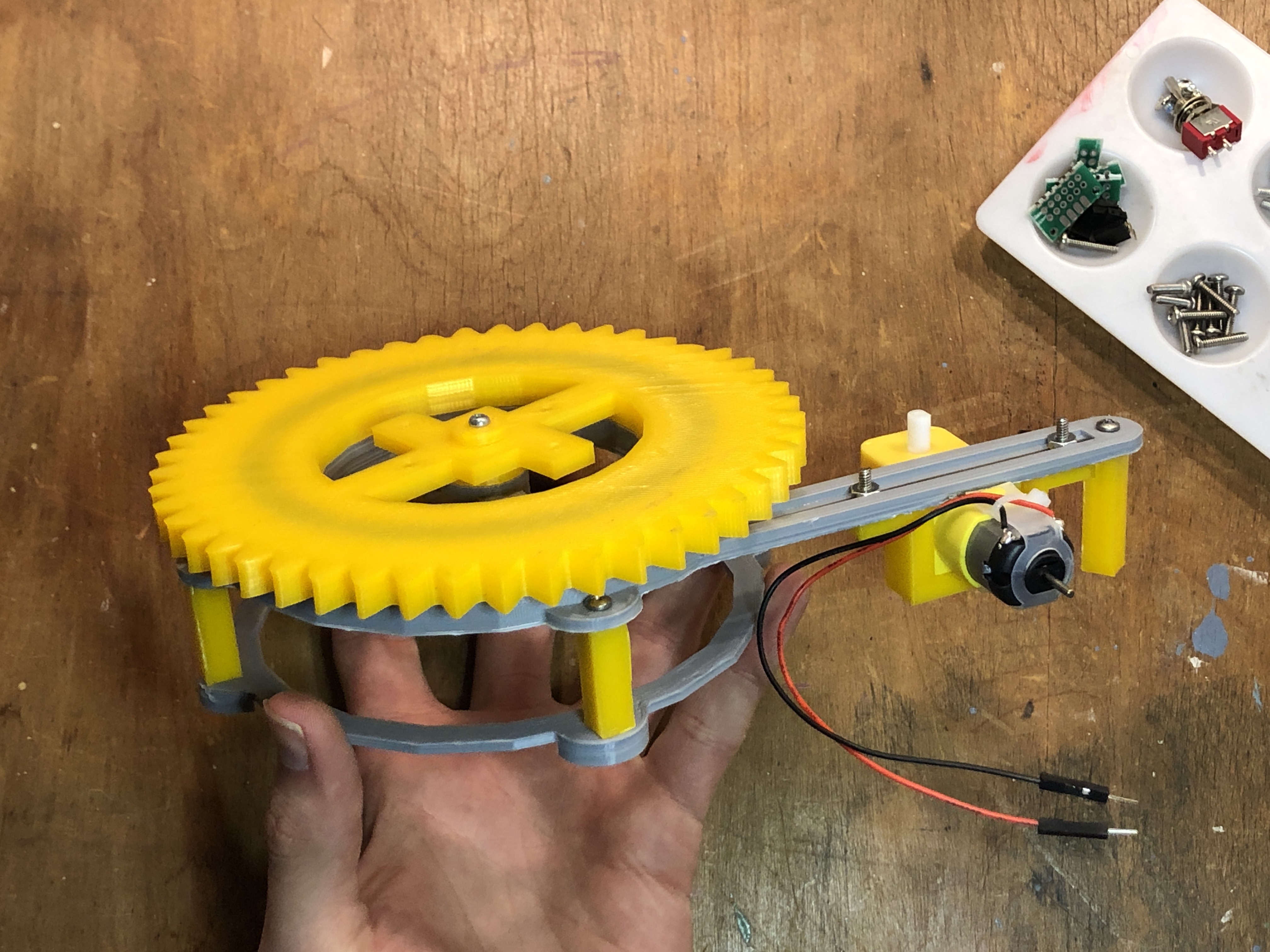
Next, repeat the previous steps to prepare a second motor assembly, and attach it to the boom arm as shown. Once again, if the little plastic nub on the hobby motor is not oriented correctly, things won't fit together properly.
Attach a second hobby motor assembly to the boom arm
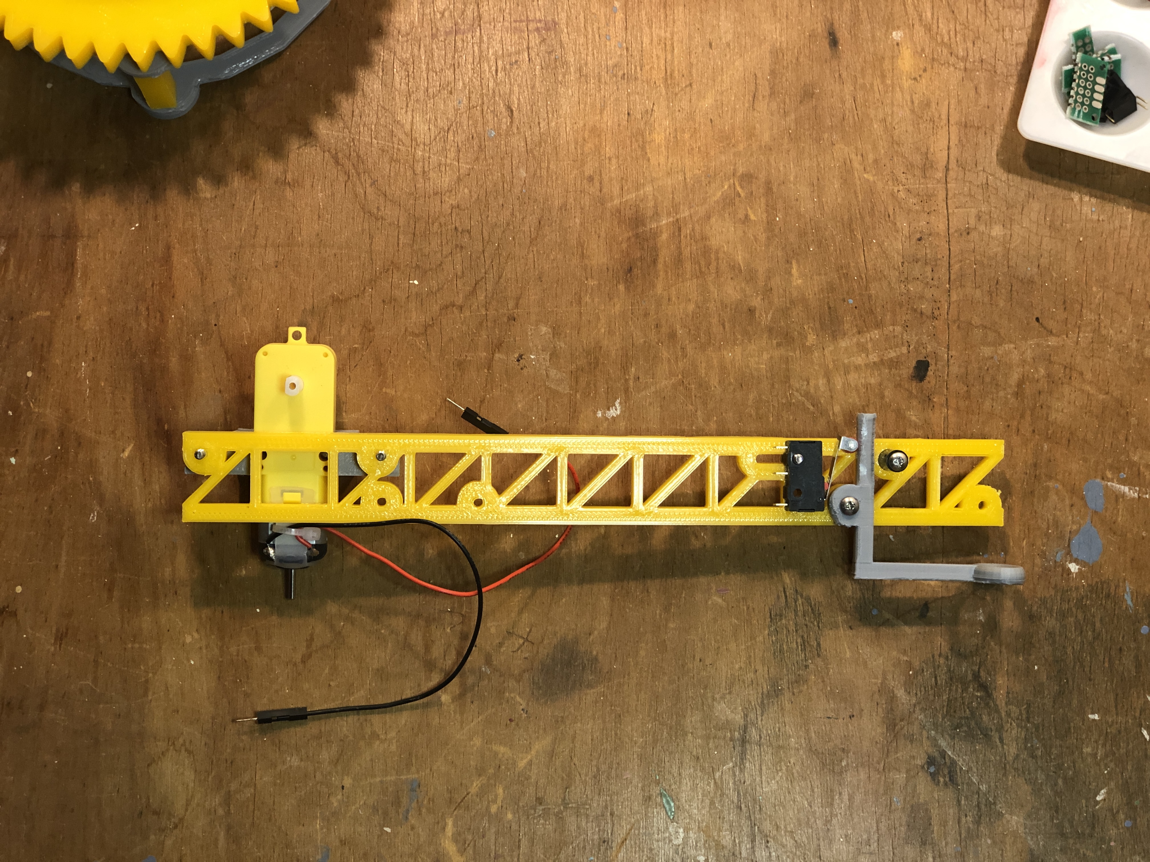
Now, use a 3/4" screw to attach the winch pulley wheel at the end of the boom arm, and then the arm is ready to attach to the vertical mast section with a couple more 4-40 screws, as shown. Now the crane is ready to be attached to the bearing base.

Attach the boom arm assembly to the crane's mast section
Flip the bearing and crane over and screw both pieces together from the underside, using a couple of nuts to tighten everything up snugly.
Attach the crane assembly to the bearing base
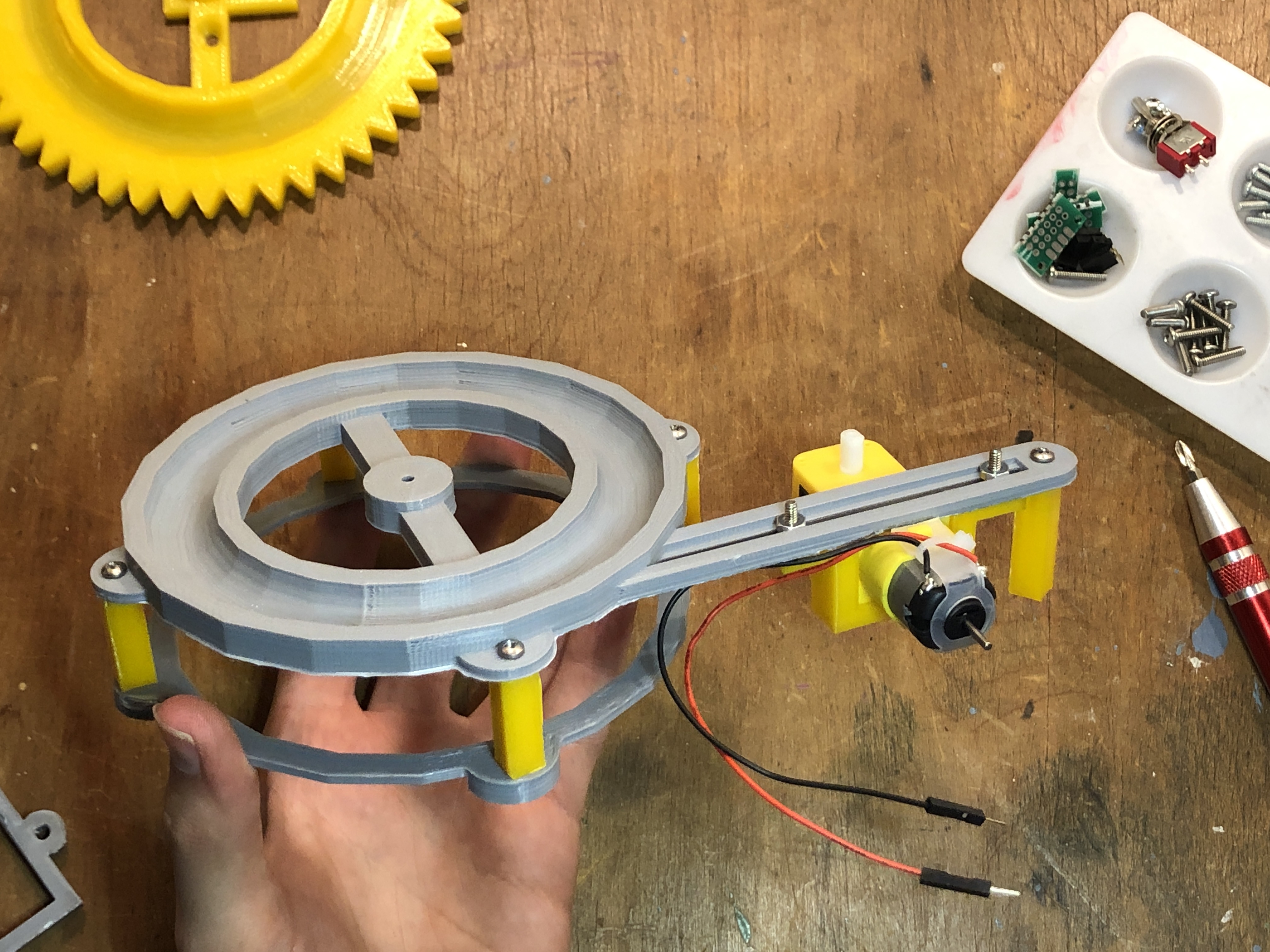
Next, snap the drive gear onto the base hobby motor, and adjust the position of the motor on the sliding mount so that the gears mesh together without grinding.
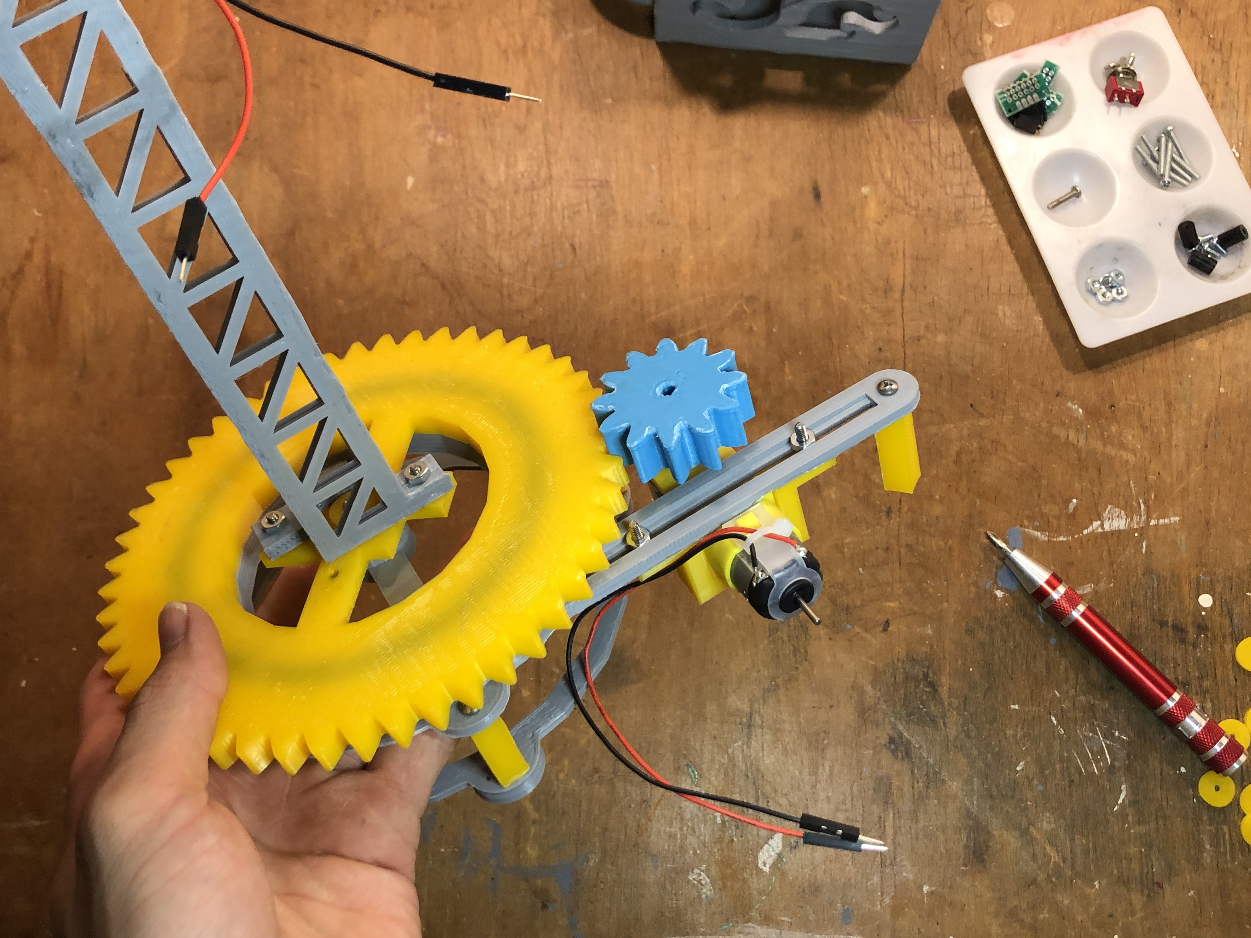
Snap the drive gear onto the motor
Finally, snap the winch spool onto the spindle of the boom arm hobby motor. It is mounted incorrectly in the picture below- you want the spool on the same side of the boom as the limit switch assembly. Now, the crane component of the project is mostly complete! Next is the joystick enclosure and MicroMod controller assembly.

Completed Crane Assembly
First thing's first, we need to be able to turn our project on and off, so we need to use some protoboard, hookup wire, and the 2-pin JST plug and socket to create a little power switch breakout. You should solder this circuit so that the JST connector for the lipo battery plugs into the power switch breakout, and the power switch breakout plugs into the JST connector of the MicroMod carrier board. The toggle should break the battery's connection to the MicroMod carrier, acting as a simple power switch.
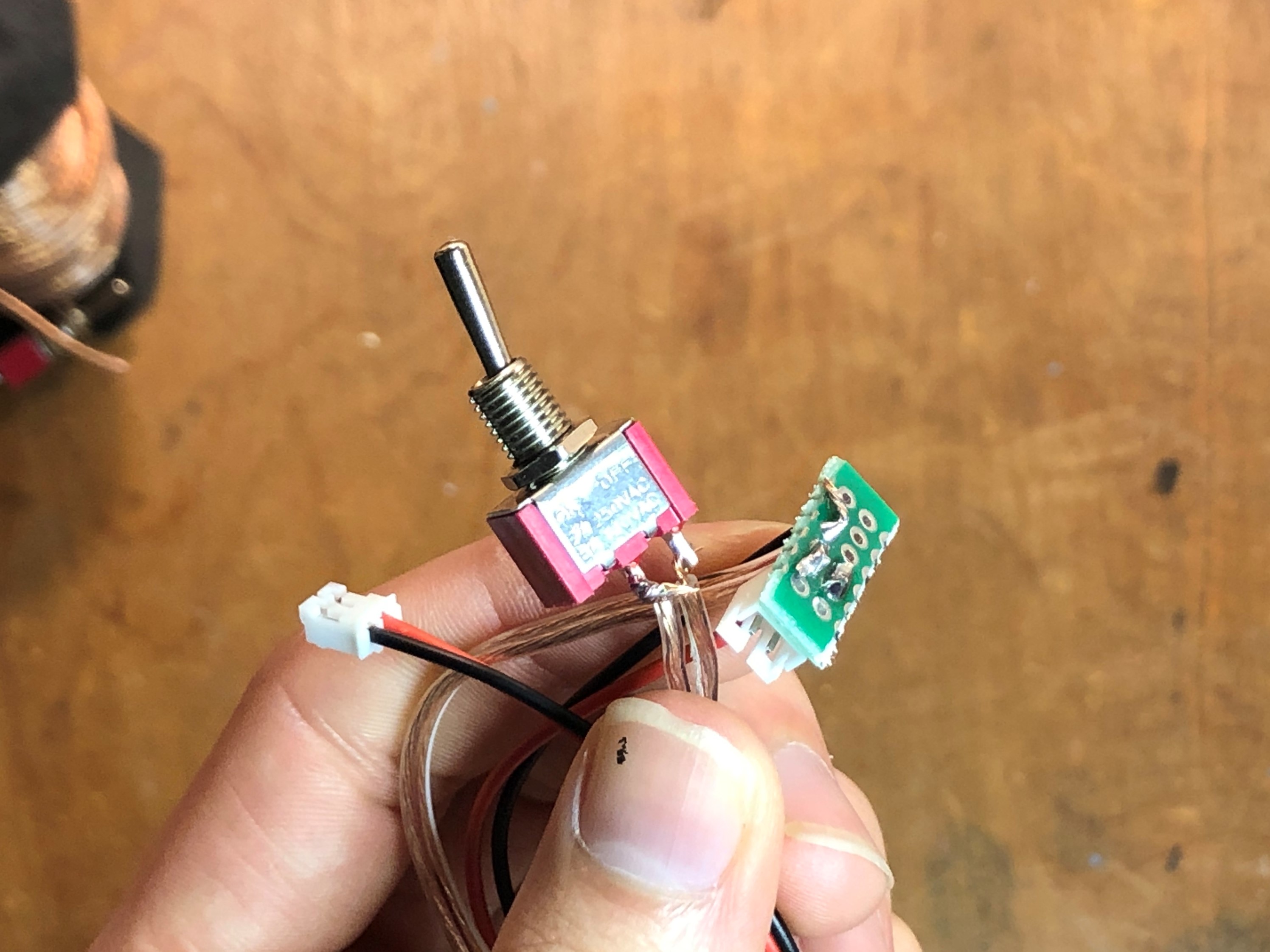
Creating a power switch breakout
Don't worry about connecting all the circuitry just yet, for now the toggle just needs to be mounted inside the joystick enclosure.

Mount the toggle into the joystick enclosure
Thread four more washer onto four more 3/4" screws, and insert each screw into one of the four mounting holes for the joystick, using four more washers to hold each screw in place. The easiest way to attach the joystick is to disassemble it and remove the metal back plate that holds the microswitches in place, as well as the red ball and plastic flange piece.
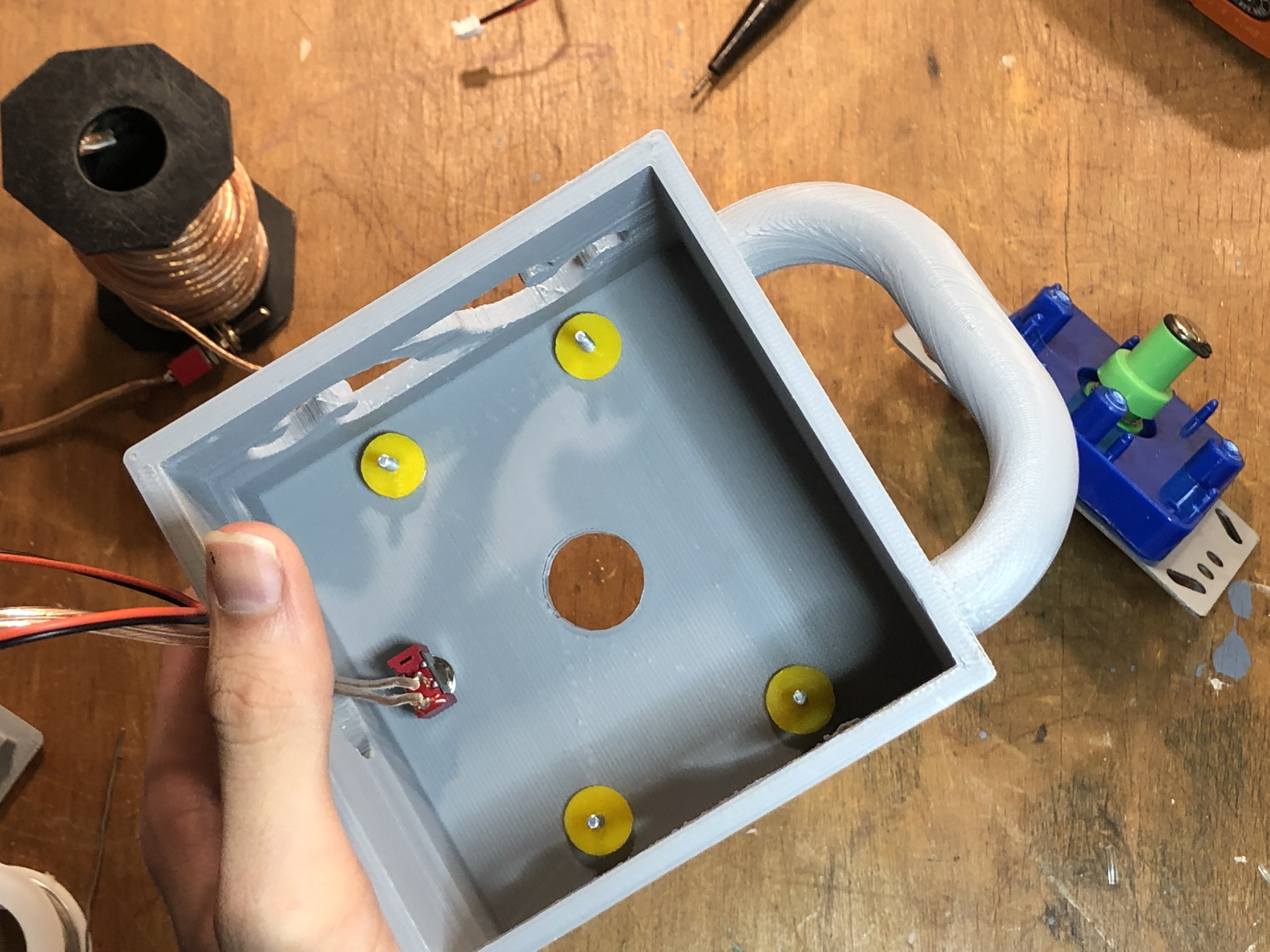
Secure the 4-40 screws for the joystick using four plastic washers (3D printed)
After inserting the main body of the joystick, secure it in place with four more washers and hex nuts, and replace the red ball and plastic flange.
Secure the Joystick with some more washers and 4-40 nuts
After soldering the SparkX Qwiic Switch breakouts onto the microswitches for the joystick, we need to manually configure each breakout's I2C address so that we know which switch is which in code. The Qwiic Switch breakout Arduino library includes the following sketch for changing the I2C address of the breakout. I used the addresses 0x62, 0x64, 0x66, and 0x68 for Left, Up, Right, and Down respectively. If you don't maintain the same ordering of your switches when you reassemble the joystick, you might need to modify your code to achieve the expected behavior.
/******************************************************************************
  A configurator for changing the I2C address on the Qwiic Button/Switch that walks
  the user through finding the address of their button, and then changing it!

  Fischer Moseley @ SparkFun Electronics
  Original Creation Date: July 30, 2019

  This code is Lemonadeware; if you see me (or any other SparkFun employee) at the
  local, and you've found our code helpful, please buy us a round!

  Hardware Connections:
  Attach the Qwiic Shield to your Arduino/Photon/ESP32 or other
  Plug the button into the shield
  Print it to the serial monitor at 115200 baud.

  Distributed as-is; no warranty is given.
******************************************************************************/

#include <SparkFun_Qwiic_Button.h>
QwiicButton button;

void setup() {
  delay(5000);
  Serial.begin(115200);
  Serial.println("Qwiic button examples");
  Wire.begin(); //Join I2C bus

  //check if button will acknowledge over I2C
  if (button.begin() == false) {
    Serial.println("Device did not acknowledge! Running scanner.");
  }
  else{
    Serial.println("Device acknowledged!");

    Serial.println();
    Serial.println("Enter a new I2C address for the Qwiic Button/Switch to use!");
    Serial.println("Don't use the 0x prefix. For instance, if you wanted to");
    Serial.println("change the address to 0x5B, you would enter 5B and press enter.");
    Serial.println();
    Serial.println("One more thing! Make sure your line ending is set to 'Both NL & CR'");
    Serial.println("in the Serial Monitor.");
    Serial.println();

    //Wait for serial data to be available
    while (Serial.available() == 0);

    if (Serial.available()) {
      uint8_t newAddress = 0;
      String stringBuffer = Serial.readString();
      char charBuffer[10];
      stringBuffer.toCharArray(charBuffer, 10);
      uint8_t success = sscanf(charBuffer, "%x", &newAddress);

      if (success) {
        if (newAddress > 0x08 && newAddress < 0x77) {
          Serial.println("Character recieved, and device address is valid!");
          Serial.print("Attempting to set device address to 0x");
          Serial.println(newAddress, HEX);

          if (button.setI2Caddress(newAddress) == true) {
            Serial.println("Device address set succeeded!");
          }

          else {
            Serial.println("Device address set failed!");
          }

          delay(100); //give the hardware time to do whatever configuration it needs to do

          if (button.isConnected()) {
            Serial.println("Device will acknowledge on new I2C address!");
          }

          else {
            Serial.println("Device will not acknowledge on new I2C address.");
          }
        }

        else {
          Serial.println("Address out of range! Try an adress between 0x08 and 0x77");
        }
      }

      else {
        Serial.print("Invalid Text! Try again.");
      }
    }
    delay(100);
  }
}

void loop() {
  //if no I2C device found or Qwiic button correctly set to new address,
  //scan for available I2C devices
  byte error, address;
  int nDevices;

  Serial.println("Scanning...");

  nDevices = 0;
  for (address = 1; address < 127; address++ )
  {
    // The i2c_scanner uses the return value of
    // the Write.endTransmisstion to see if
    // a device did acknowledge to the address.
    Wire.beginTransmission(address);
    error = Wire.endTransmission();

    if (error == 0)
    {
      Serial.print("I2C device found at address 0x");
      if (address < 16)
        Serial.print("0");
      Serial.print(address, HEX);
      Serial.println("  !");

      nDevices++;
    }
    else if (error == 4)
    {
      Serial.print("Unknown error at address 0x");
      if (address < 16)
        Serial.print("0");
  Serial.println(address, HEX);
}
  }
  if (nDevices == 0)
    Serial.println("No I2C devices found\n");
  else
    Serial.println("done\n");

  delay(5000);           // wait 5 seconds for next scan
}
Now, connect all four microswitches together with some Qwiic cables, and as mentioned before, make sure to keep track of the I2C addresses of your switches as you reassemble the joystick. I labeled mine by writing on the metal back plate in permanent marker.
Reattach the joystick's microswitches
The final step of reassembling the joystick is selecting the directionality of the joystick using the green plastic bezel parts. For this project, we want to set the joystick to four directions by mounting the green plastic bezel with the clover shaped hole around the joystick shaft as shown here:
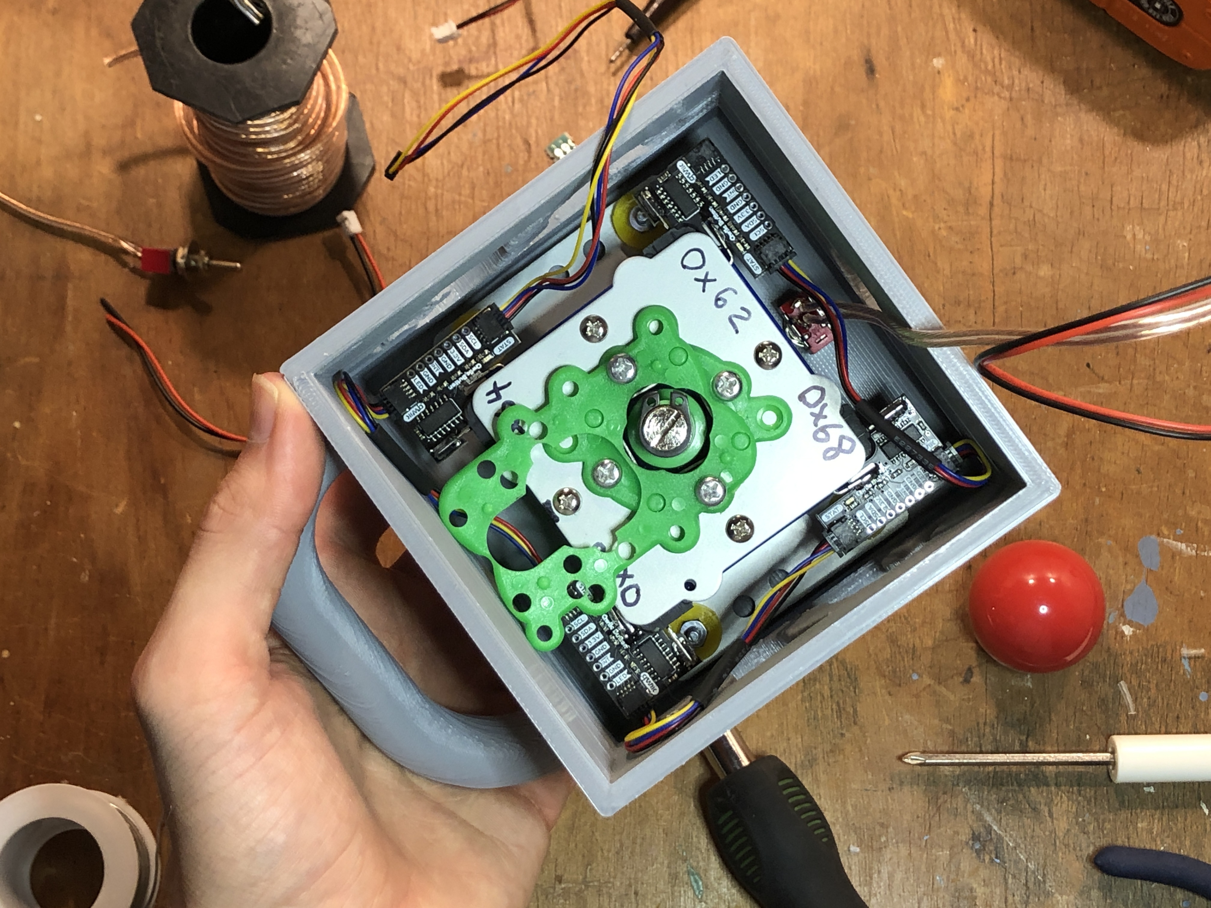
Use the green plastic parts to set the joystick to only four directions
With the joystick and power switch mounted, the top half of the joystick enclosure is complete.
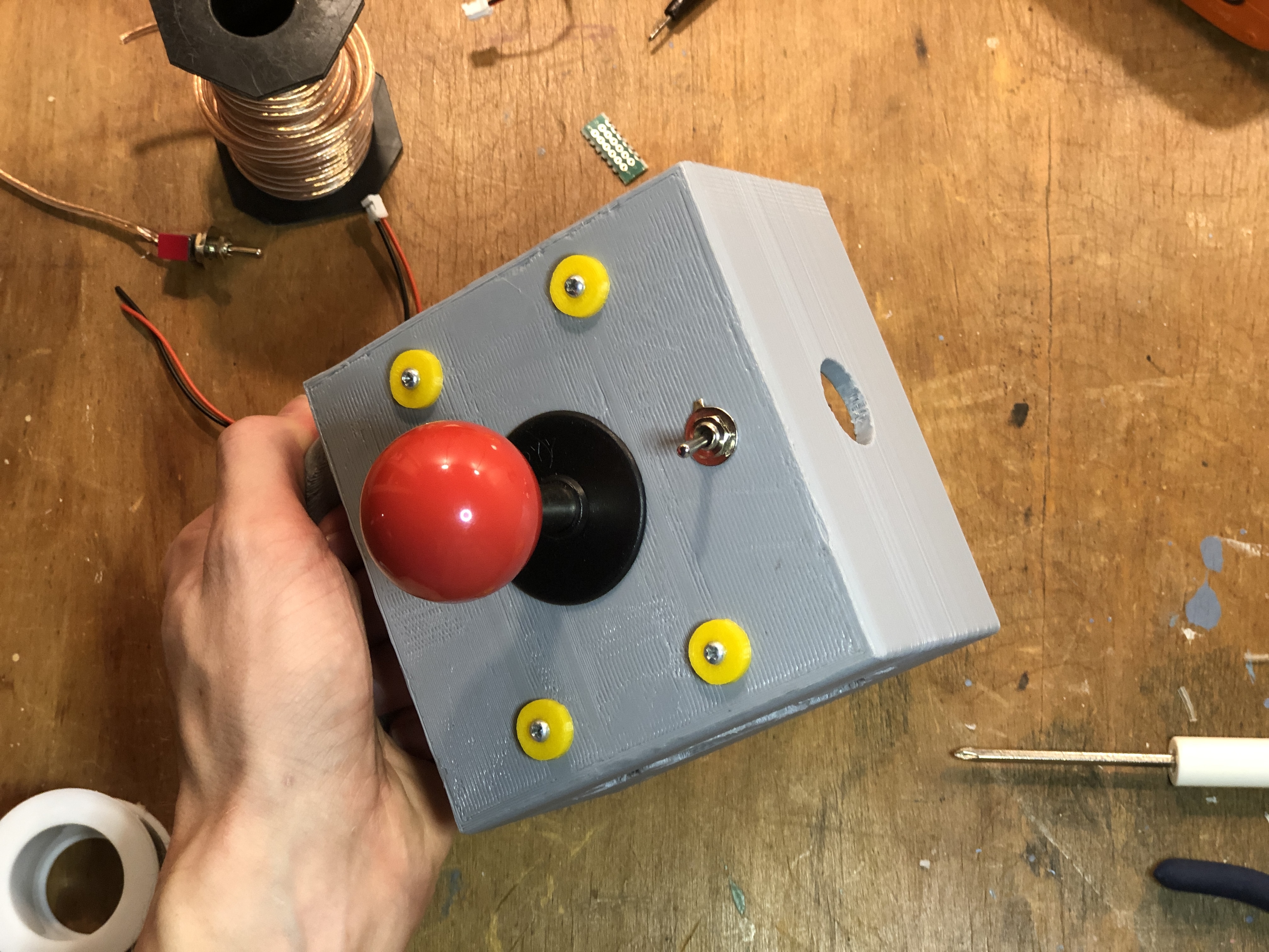
Completed top side of joystick enclosure
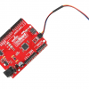
Finally, it's time to assemble the brains of the project, which utilizes a MicroMod Qwiic carrier (single) as its base with a SAMD51 processor inserted into the M.2 connector and secured with the included screw.

Insert the SAMD51 processor into the MicroMod Qwiic carrier (single)
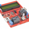
Using a couple 1/4" 4-40 screws, attach the Qwiic Motor Driver to two of the carrier board's threaded standoffs, so that it hangs over the side as shown. Now is also a good time to attach some jumper wire to the power screw terminals. I soldered a 2-pin header to the carrier board's 3.3V and GND pins to supply power to my hobby motors, but my header wore out eventually and I just soldered the jumper wires straight to the pins at that point.
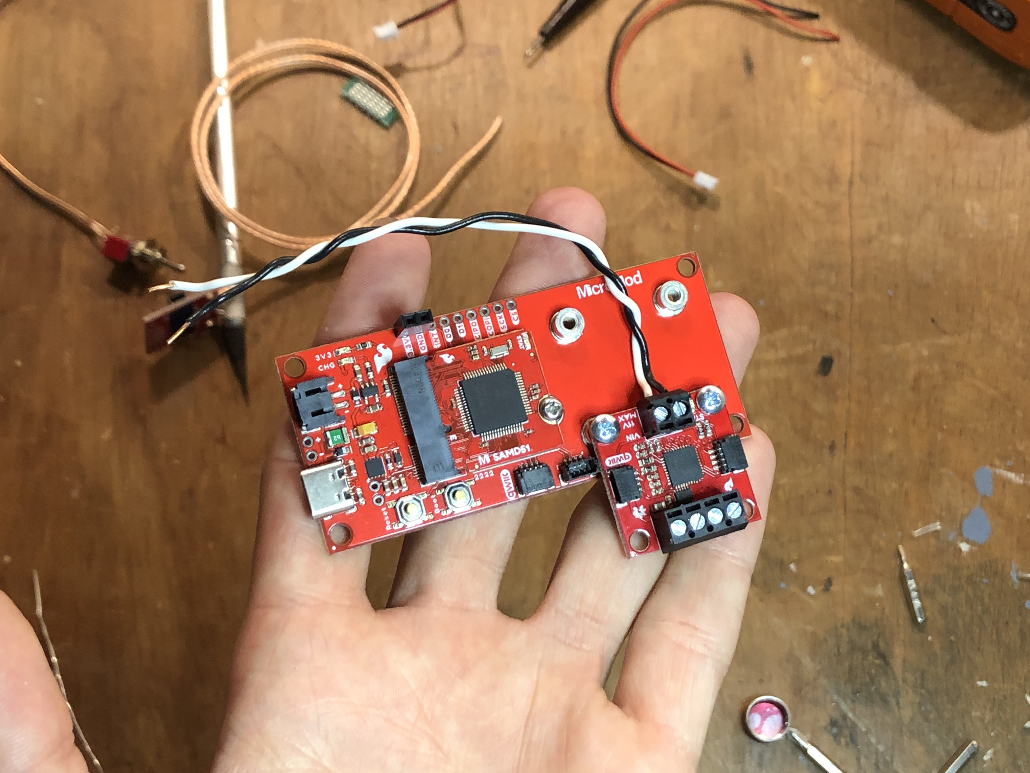
Secure the Qwiic Motor Driver to two of the carrier's threaded standoffs
Next, use the other set of available threaded standoffs to attach the Qwiic Button Breakout to the carrier. I soldered a length of stranded wire to the pins for the button on the Qwiic Button Breakout so that I could connect the winch limit switch later. This is also a good time to connect the carrier and breakouts together with Qwiic cables.
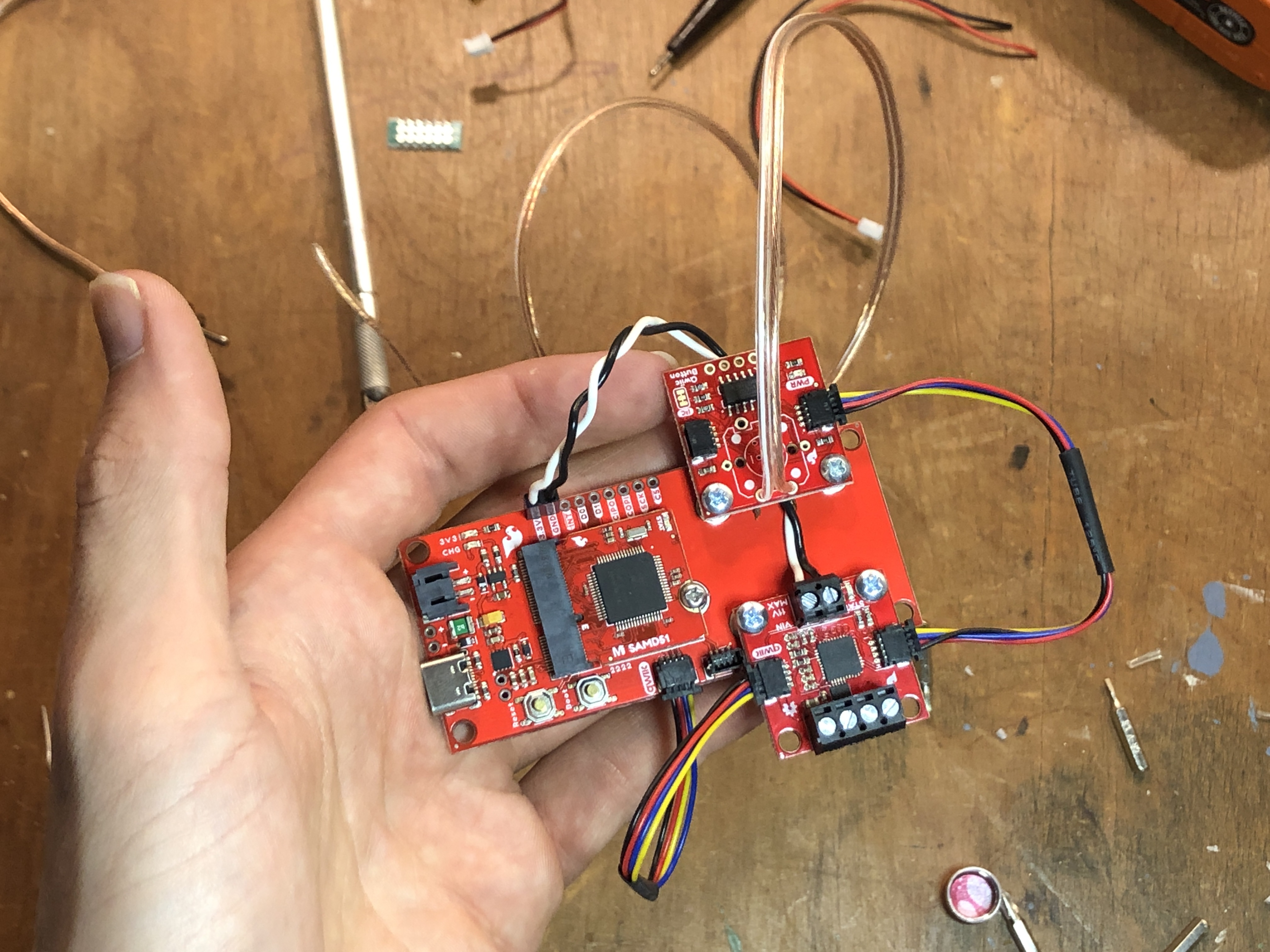
Secure the Qwiic Button Breakout to the other two standoffs
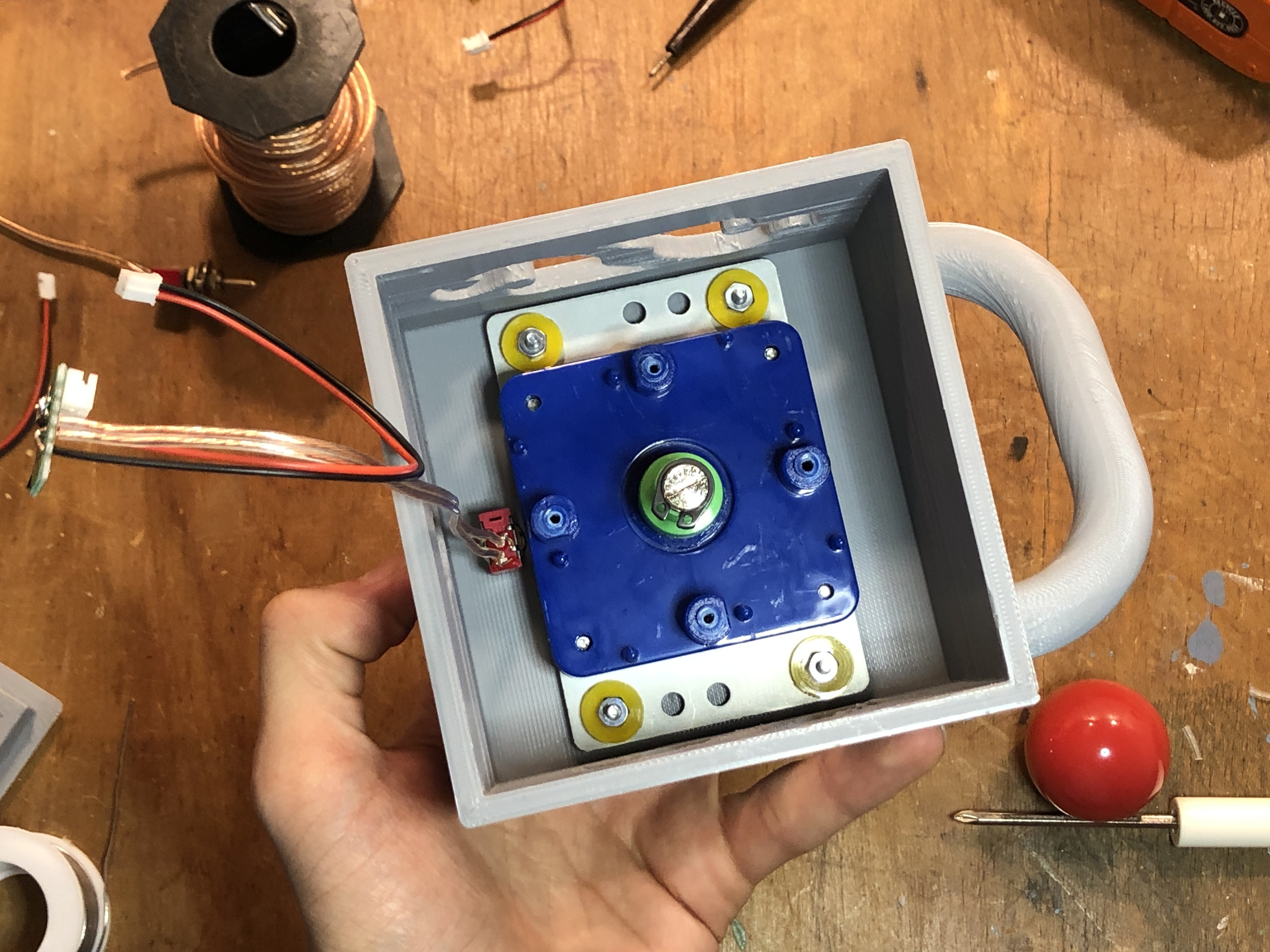
To hold my lipo battery in place, I used a piece of double-sided tape to adhere it to the underside of the carrier board. Next, I added some 3/4" screws and standoffs to prepare the carrier to be mounted to the bottom piece of the enclosure.
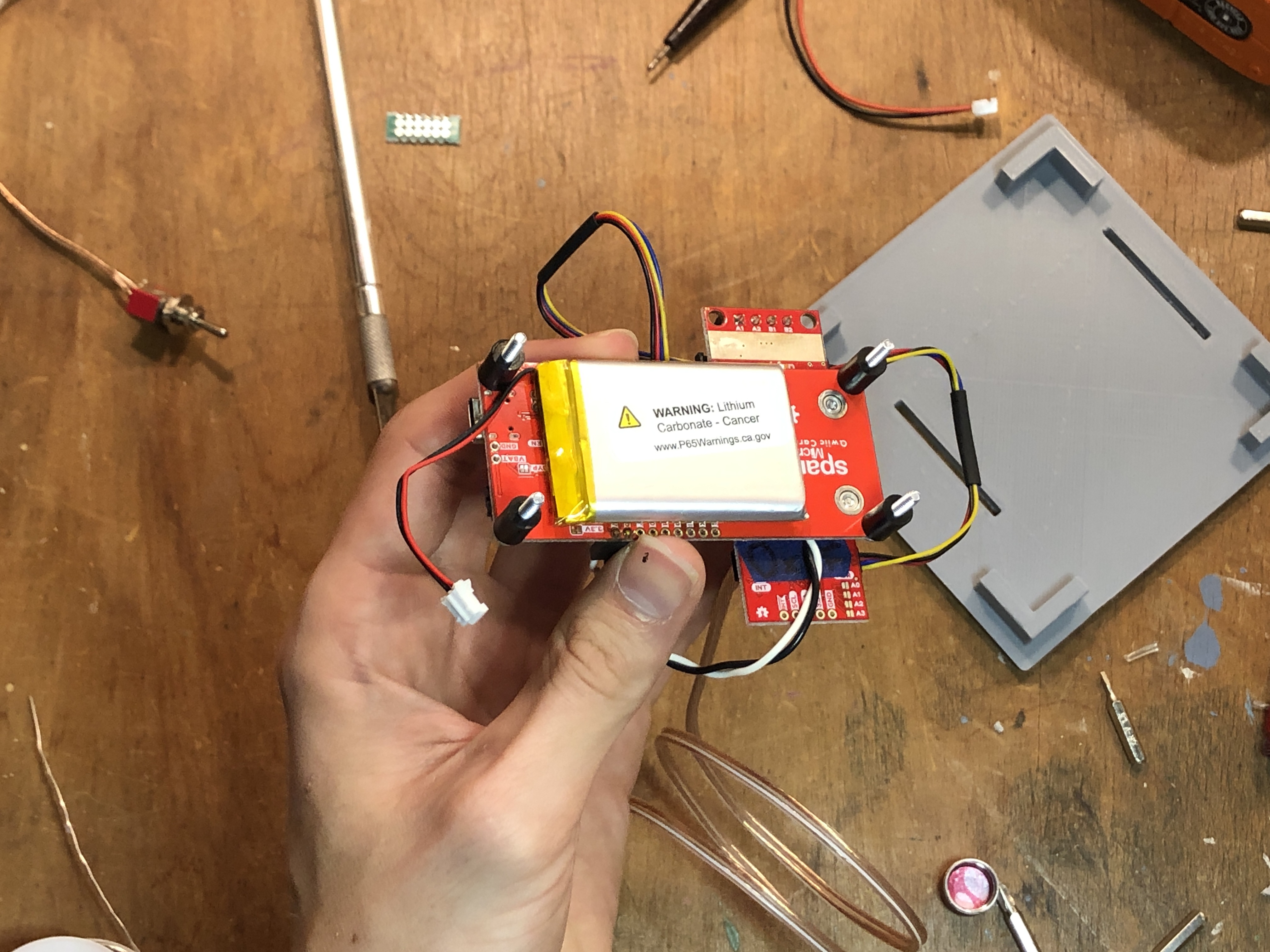
Attach the lipo battery to the underside of the carrier with double-sided tape
Now the carrier board can be snapped into the slots on the enclosure bottom as shown, with four hex nuts holding everything together.
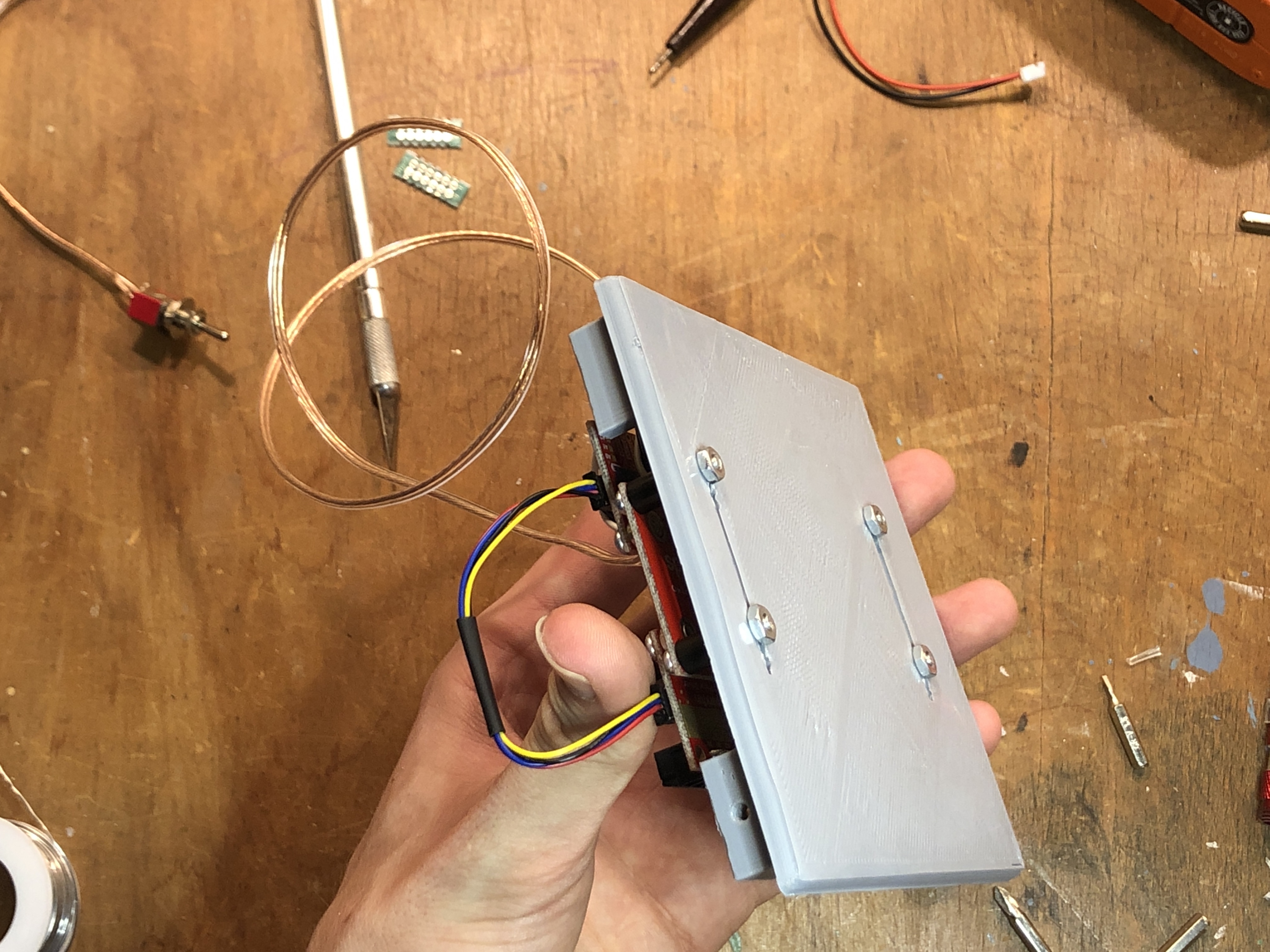
Use 4-40 nuts to attach the MicroMod carrier to the enclosure bottom
Before we can bring all the parts of the crane together, we need to make some hookup wires to attach the hobby motors to the Motor Driver Breakout. To do this, I took a couple two-pin headers and pieces of protoboard, and soldered them to some stranded speaker wire, enclosing everything in heat-shrink tubing. Strip the opposite ends of the wires to insert into the breakout's screw terminals (tinning the ends with a soldering iron is probably a good idea to prevent them from breaking).
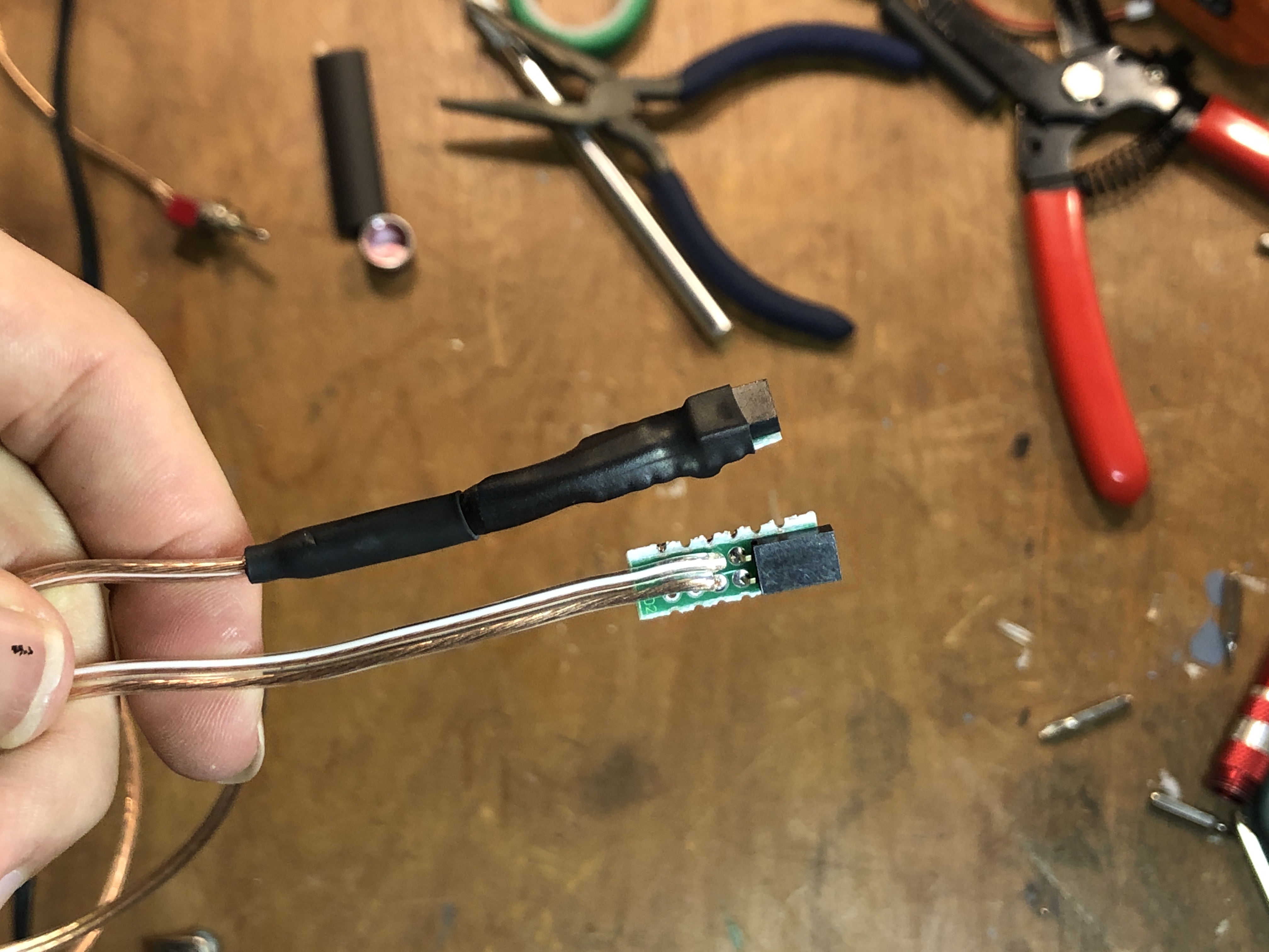
2-pin female headers soldered to jumper wire for motor hookup
With our crane assembly, joystick assembly, and enclosure underside and hookup wires, we're ready to install the Crane Control Arduino sketch and put everything together.
Now we're ready to put everything together!
First, connect your MicroMod Carrier to your computer with a USB cable and, assuming you have already followed the various hookup guides for the SAMD51 processor, Qwiic Button breakout, and Qwiic Motor Driver, upload the following sketch to your board. Once it's successfully uploaded, unplug the USB cable from the board.
/******************************************************************************
  Marcus Stevenson @ SparkFun Electronics
  Original Creation Date:August 28, 2021

  This code is Lemonadeware; if you see me (or any other SparkFun employee) at the
  local, and you've found our code helpful, please buy us a round!

  Hardware Connections:
  (blog link)
  Print it to the serial monitor at 115200 baud.

  Distributed as-is; no warranty is given.
******************************************************************************/

#include <SparkFun_Qwiic_Button.h>
#include <Arduino.h>
#include <stdint.h>
#include "SCMD.h"
#include "SCMD_config.h" //Contains #defines for common SCMD register names and values
#include "Wire.h"

SCMD myMotorDriver;

QwiicButton limit; // default addr.
QwiicButton joy1;//LEFT   0x62
QwiicButton joy2;//UP     0x64
QwiicButton joy3;//RIGHT  0x66
QwiicButton joy4;//DOWN   0x68

#define LEFT_MOTOR 0  //ROTATION
#define RIGHT_MOTOR 1 //WINCH

void setup() {
  delay(50);
  Serial.begin(115200);
  Serial.println("Qwiic Crane Example");
  Wire.begin(); //Join I2C bus

  myMotorDriver.settings.commInterface = I2C_MODE;
  myMotorDriver.settings.I2CAddress = 0x5D;
  myMotorDriver.begin();
  Serial.print("Waiting for enumeration...");
  while ( myMotorDriver.ready() == false );
  Serial.println("Done.");
  while ( myMotorDriver.busy() );
  myMotorDriver.enable();
  myMotorDriver.setDrive( LEFT_MOTOR, 0, 0); //Stop motor
  myMotorDriver.setDrive( RIGHT_MOTOR, 0, 0); //Stop motor
  Serial.println();

  //check if button will acknowledge over I2C
  if (limit.begin() == false) {
    Serial.println("Limit Switch did not acknowledge! Freezing.");
    while (1);
  }
  Serial.println("Limit Switch acknowledged.");
  if (joy1.begin(0x62) == false) {
    Serial.println("joy1 did not acknowledge! Freezing.");
    while (1);
  }
  Serial.println("Joy1 acknowledged.");
  if (joy2.begin(0x64) == false) {
    Serial.println("joy2 did not acknowledge! Freezing.");
    while (1);
  }
  Serial.println("Joy2 acknowledged.");
  if (joy3.begin(0x66) == false) {
    Serial.println("joy3 did not acknowledge! Freezing.");
    while (1);
  }
  Serial.println("Joy3 acknowledged.");
  if (joy4.begin(0x68) == false) {
    Serial.println("joy4 did not acknowledge! Freezing.");
    while (1);
  }
  Serial.println("Joy4 acknowledged.");
}

void loop() {
  //check if button is pressed, and tell us if it is!
  while (limit.isPressed() == false){
    if (joy1.isPressed() == true){
      myMotorDriver.setDrive(LEFT_MOTOR, 0, 150);
    }
    if (joy3.isPressed() == true){
      myMotorDriver.setDrive(LEFT_MOTOR, 1, 200);
    }
    if (joy1.isPressed() == false && joy3.isPressed() == false){
      myMotorDriver.setDrive(LEFT_MOTOR, 0, 0);
    }
    if (joy2.isPressed() == true){
      myMotorDriver.setDrive(RIGHT_MOTOR, 0, 200);
    }
    if (joy4.isPressed() == true){
      myMotorDriver.setDrive(RIGHT_MOTOR, 1, 200);
    }
    if (joy2.isPressed() == false && joy4.isPressed() == false){
      myMotorDriver.setDrive(RIGHT_MOTOR, 0, 0);
    }
  }
  myMotorDriver.setDrive(LEFT_MOTOR, 0, 0);
  myMotorDriver.setDrive(RIGHT_MOTOR, 0, 0);
  delay(20); //Don't hammer too hard on the I2C bus
}
With the sketch uploaded, we can now assemble the top and bottom halves of the joystick enclosure. Connect the bare ends of your hookup wires to the screw terminals of the Qwiic Motor Driver as shown.
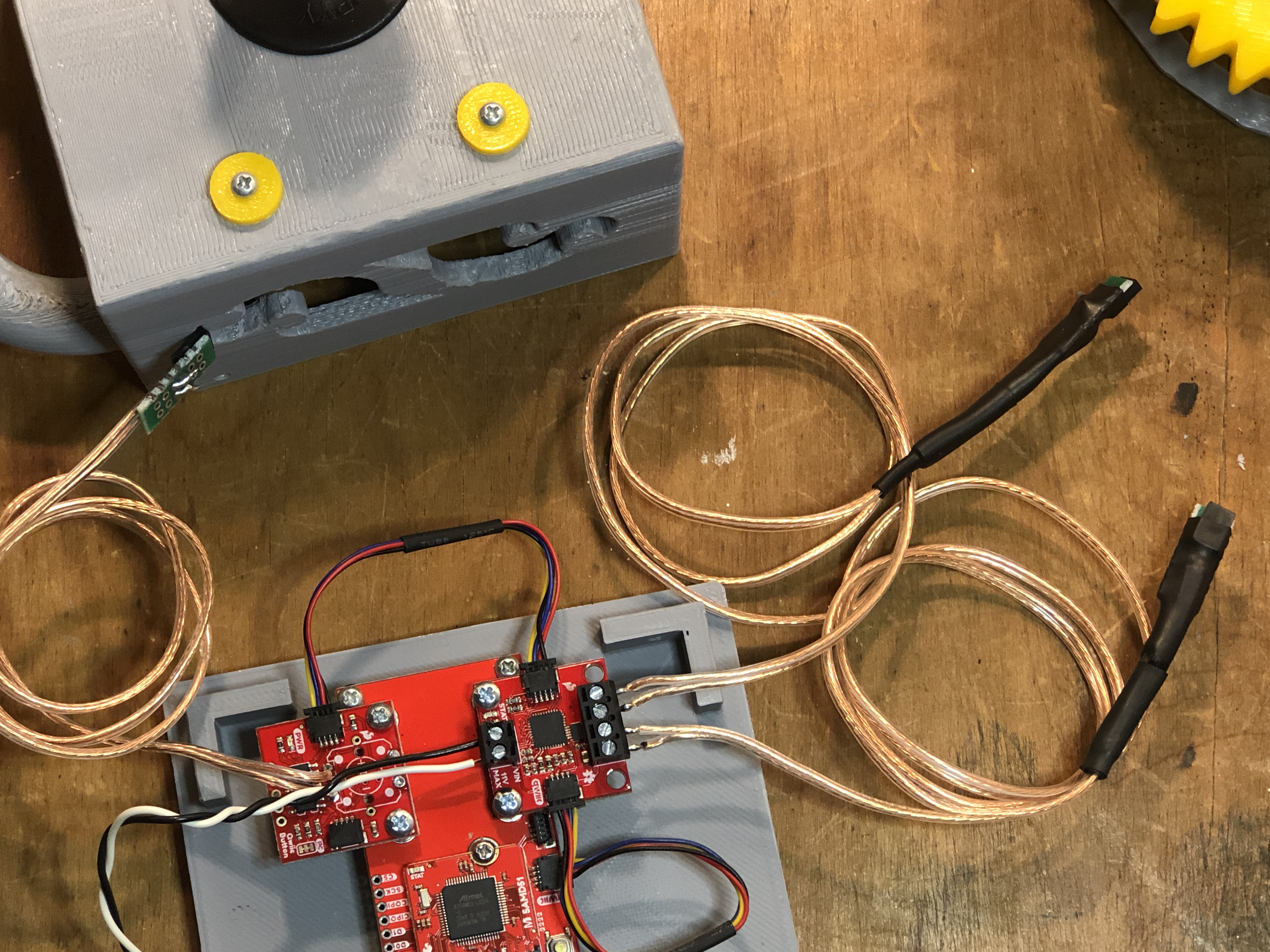
Connect the hookup wires to the Qwiic Button Breakout and Motor Driver
Carefully thread the hookup wires for the motors and limit switch through the hole on the side of the joystick enclosure.
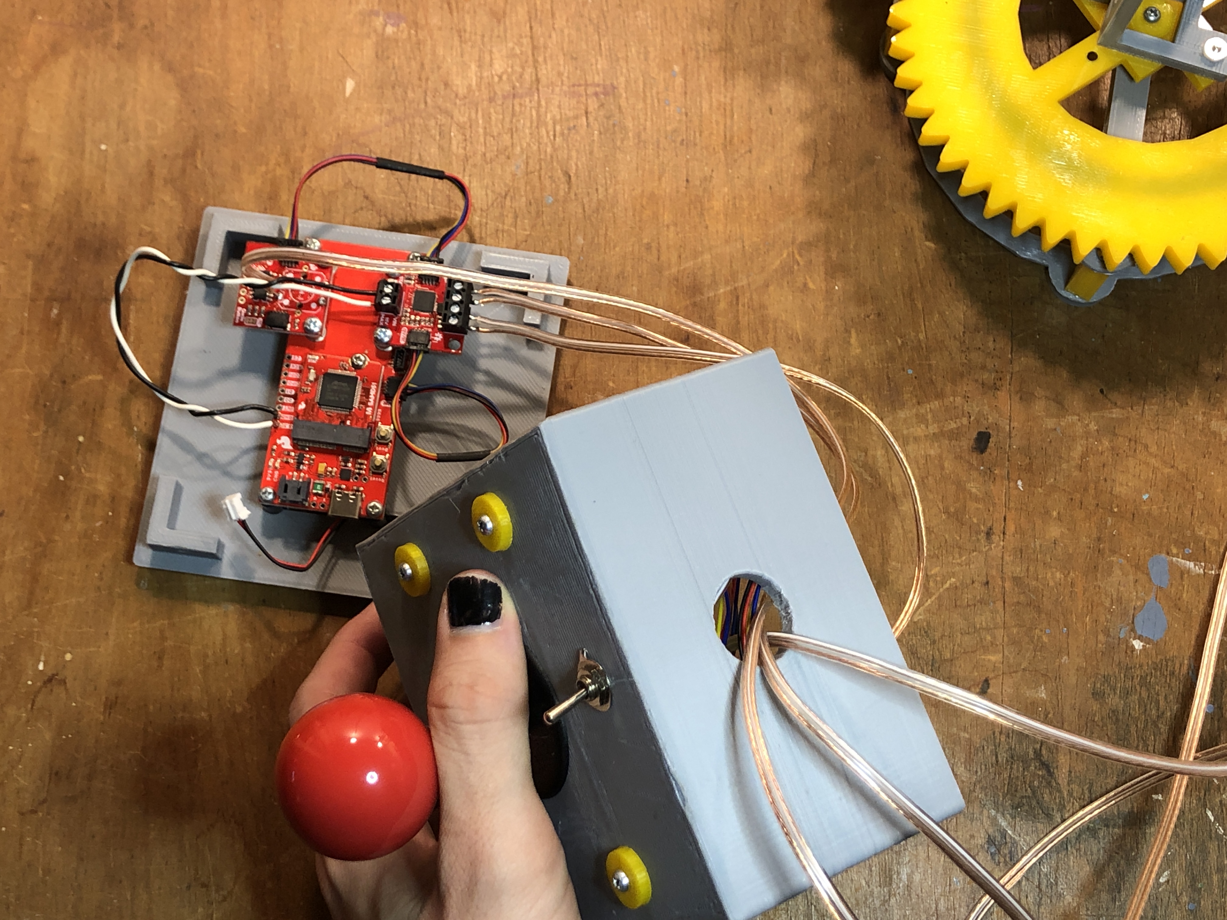
Carefully pull your hookup wires through the hole in the enclosure's top side
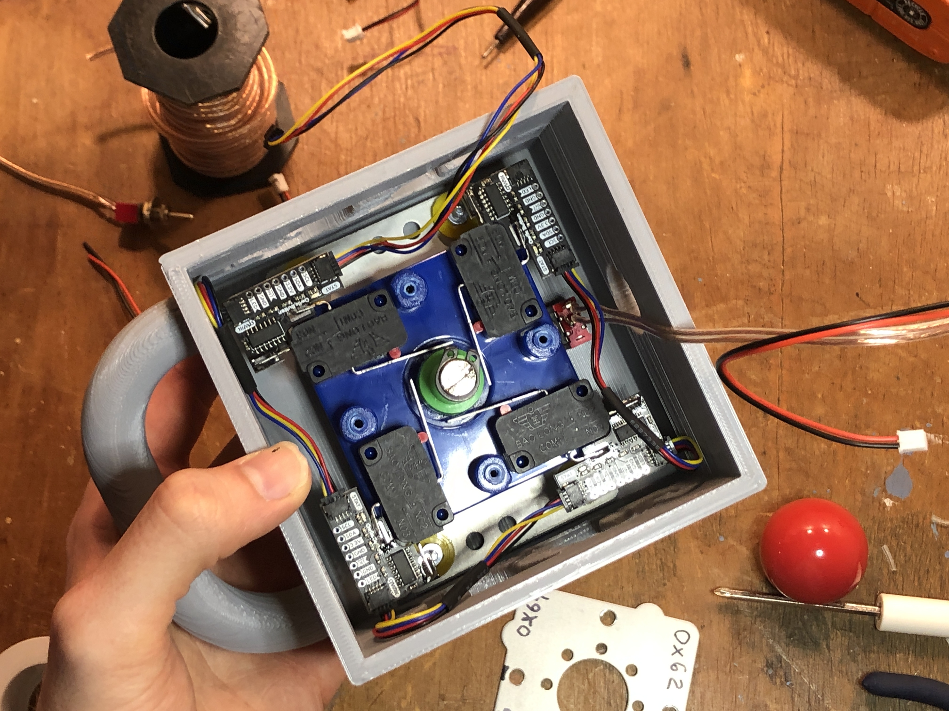
Next, connect the JST connector of the lipo battery to the female connector of the power switch breakout, then connect the JST from the power breakout into the female JST connector on the MicroMod carrier board. If everything is wired correctly, you should see the carrier's power LED illuminate when the toggle is switched on. If you don't see the power light and you are sure your lipo is charged, this could mean you have mixed up the polarity of your power switch circuit and need to double check/redo it. Lastly, connect the joystick's button breakouts to the carrier board with a 200mm flexible Qwiic cable. All four Qwiic Switch breakouts, the Qwiic Button Breakout, and the Qwiic Motor Driver should be connected together via Qwiic cables and connected to the MicroMod carrier's horizontal Qwiic connector. Each Qwiic breakout has a power indicator LED on it somewhere, so if there is a problem with your circuit, a good way to locate it is to first check for lit power LEDs.
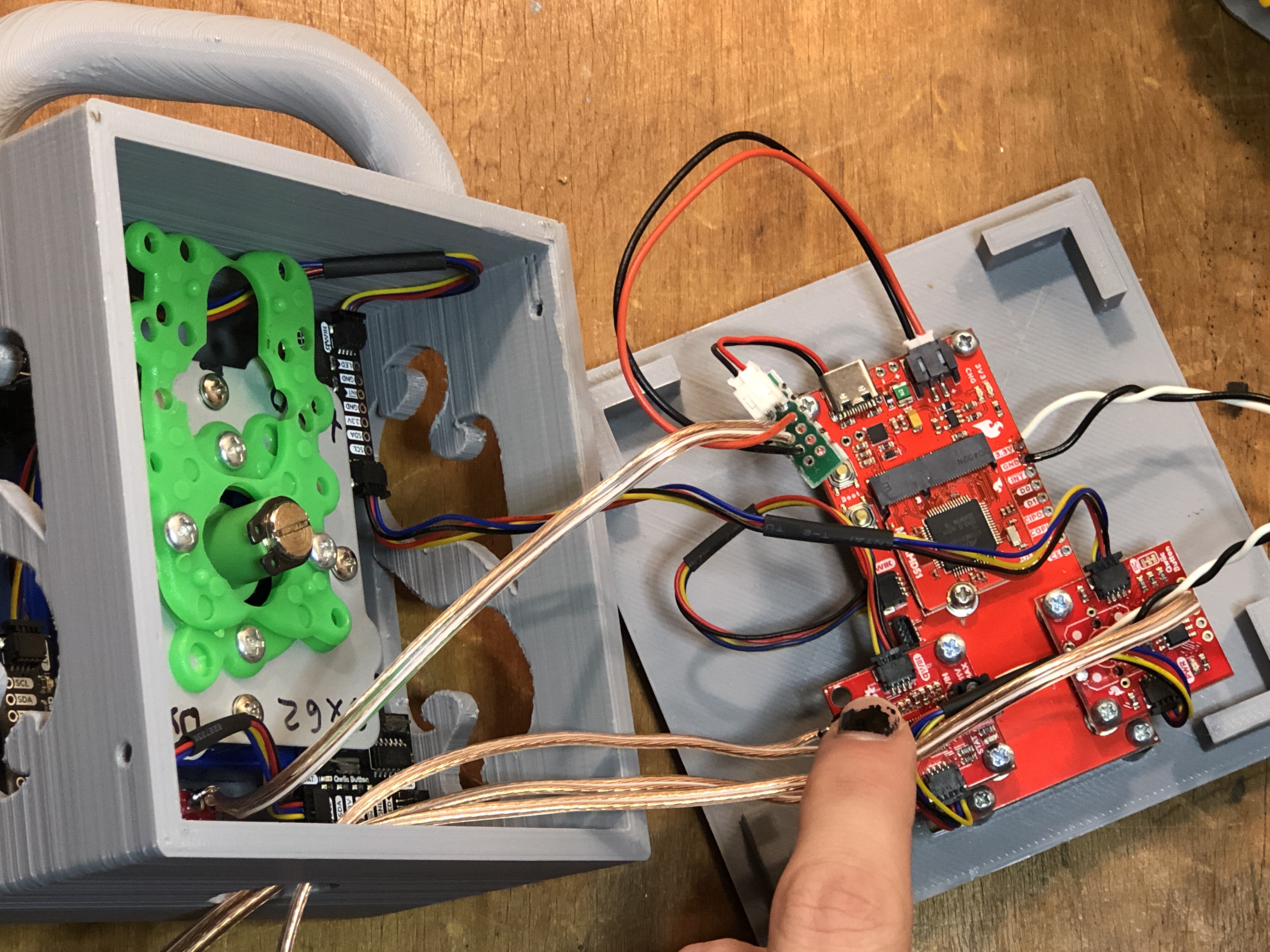
Battery and power switch hookup
With the sketch installed and all the internal wiring connected, we can now carefully sandwich the two halves of the joystick enclosure together, making sure to align the screw holes like so:
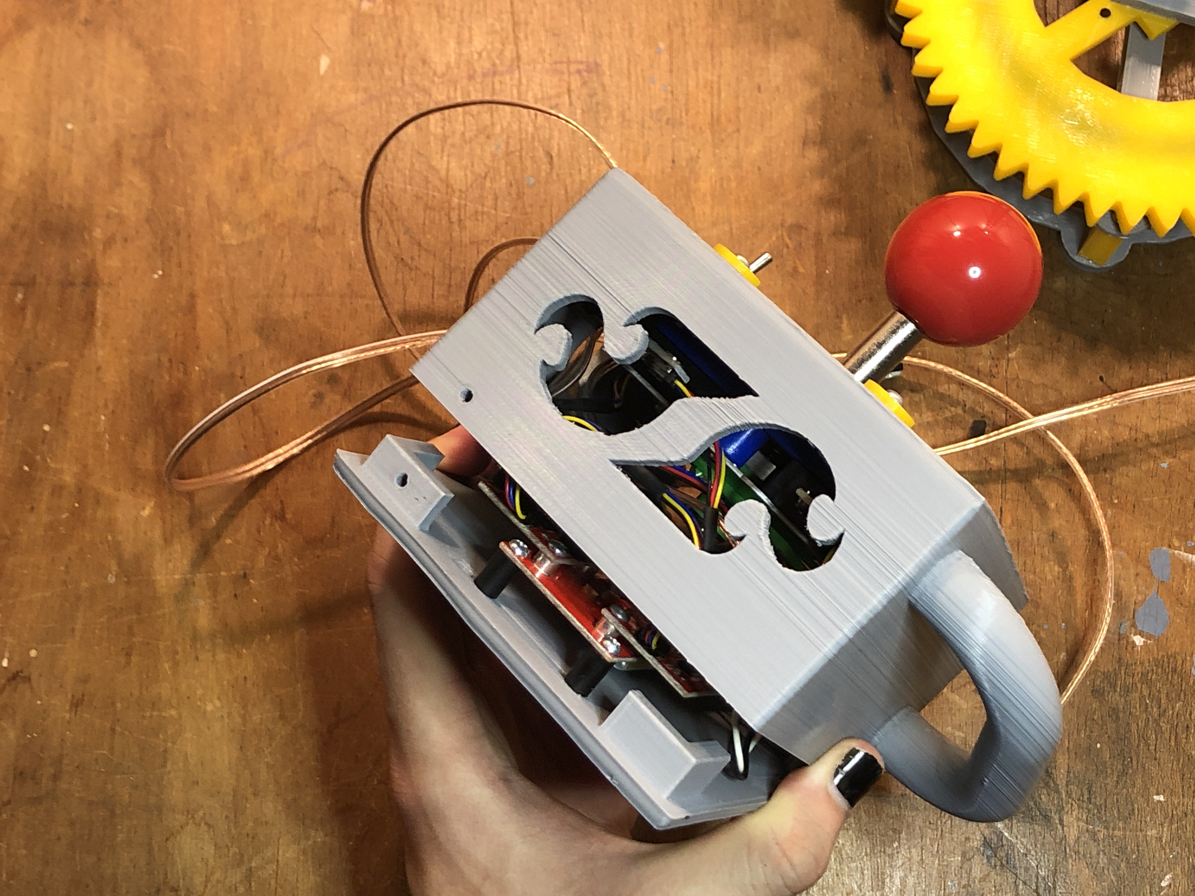
Carefully align the top and bottom enclosure parts
Use just two more 3/4" 4-40 screws to secure everything in place.
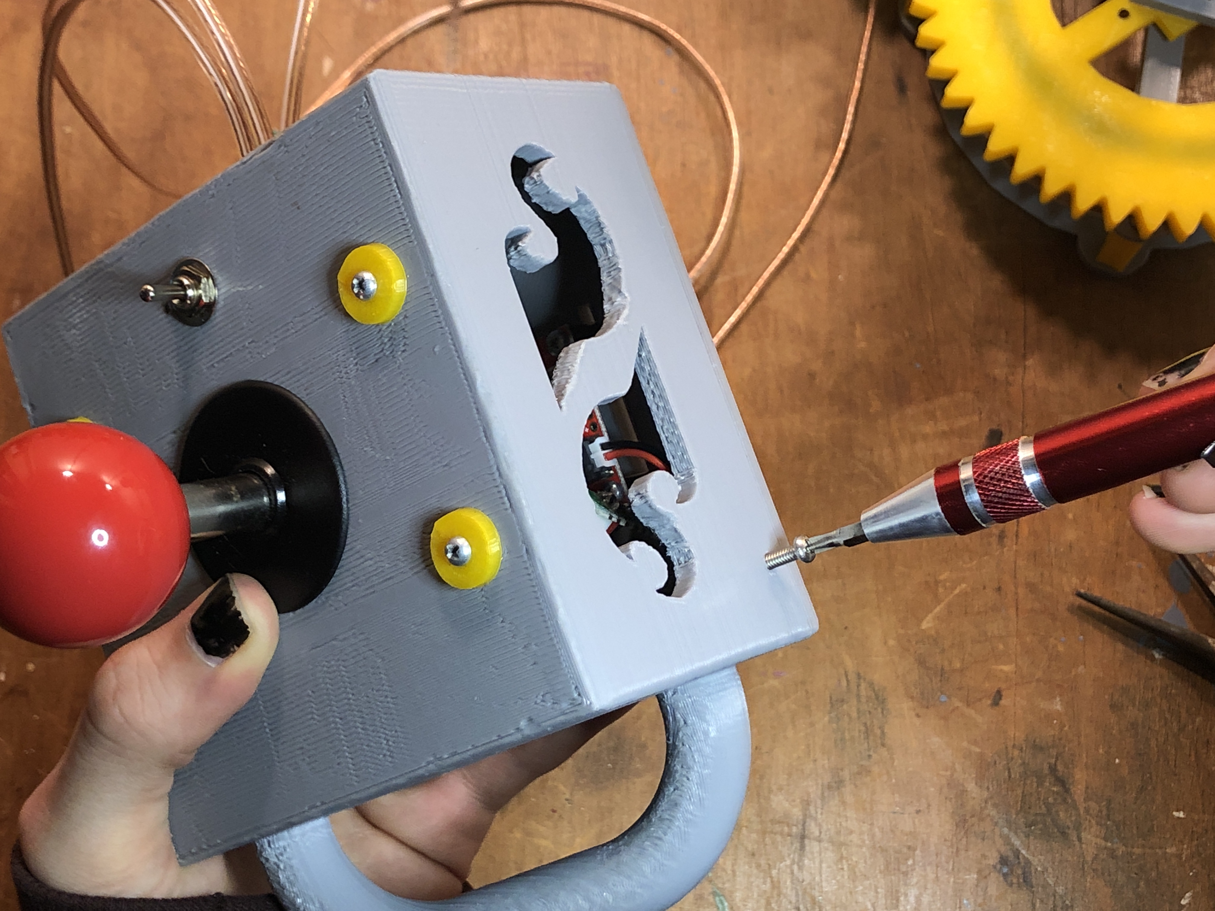
Hold the parts together with a couple screws
Now it's time to attach the wires from our motors and winch limit switch to the controller. The motors attach easily using the female headers we prepared earlier, but the limit switch will need to be soldered (or you could create another female header to connect to the limit switch). Zip ties are helpful to prevent the various cables tangling.
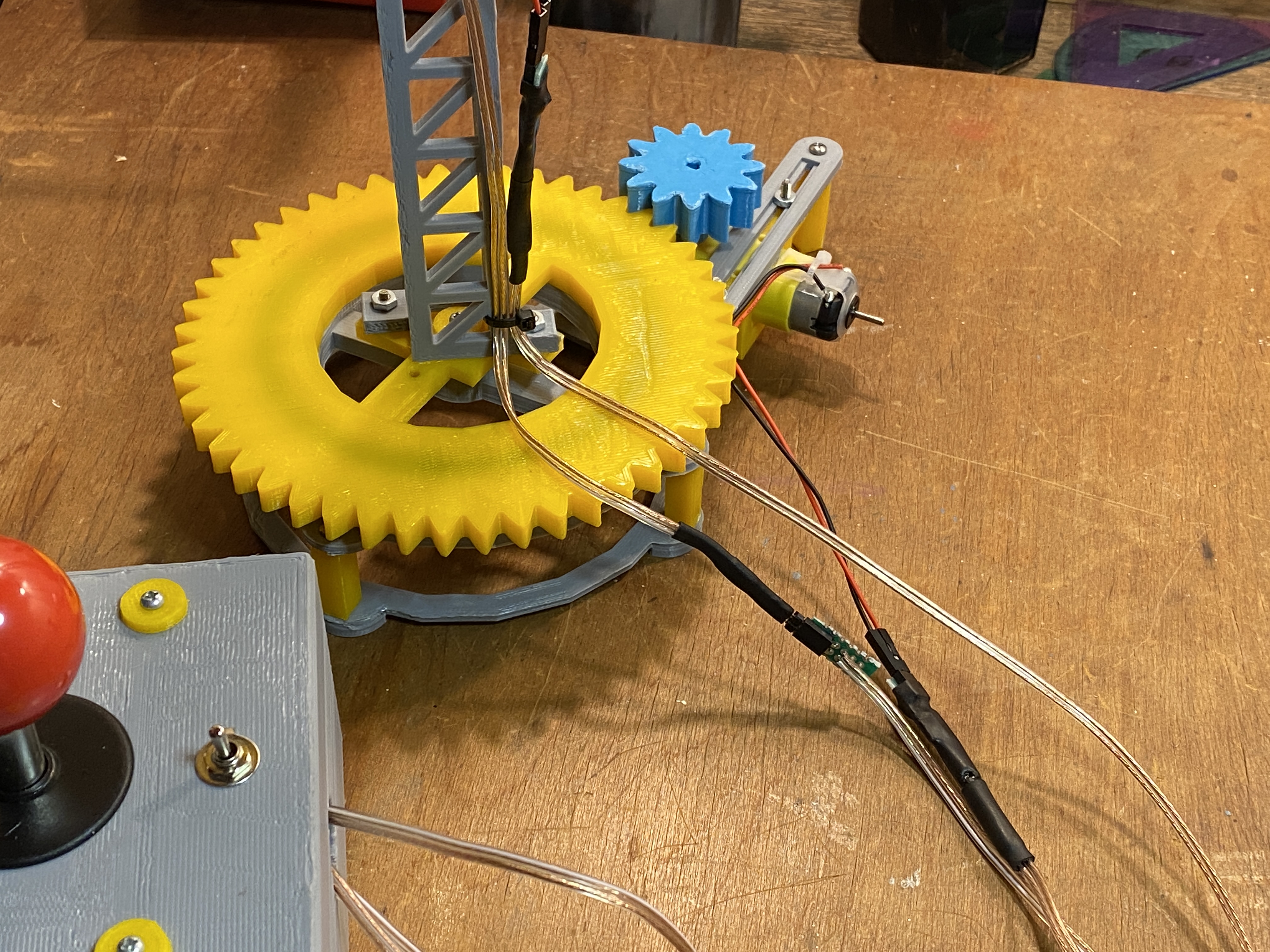
Connect the motors and hoist limit switch and secure with zip tie
With everything connected, the Qwiic Crane should be ready to fire up! You'll need to wind some string onto the winch and thread it over the pulley and through the limit switch apparatus. The 3D files include a hook that you can use, but I simply attached a small plumb weight to my crane for demonstration purposes. If the motors behave unexpectedly, you might need to swap the polarity of your connections, or check on the ordering of your microswitches on the joystick assembly. If you don't arrange your microswitches with the I2C addresses perfectly corresponding to the instructions, you may need to tinker with the Arduino sketch to sort out which address corresponds to which joystick direction. The crane should behave as shown below. If the limit switch is pressed by the winch being raised too far, the crane should automatically lower the winch and prevent a failure. In part two of this project, I intend to address some of the other design mistakes and challenges of the crane by making it wireless, and adding a few other features, so if you made it this far, stay tuned for more!
Everything should be working!


Great little project, and nice write up. I want to thank you, though, for bringing back fond memories of my father telling me of all the developments and improvements in crane technology, and other construction technologies, made by the U.S. Army Corps of Engineers prior to World War II. Dad was in the Corps from about 1937 through the end of the war.
I really would like to know how you used tinkercad to make parts like this. I have had experiences with using tinkercad to make precise and complicated parts, and it can be very hard because tinkercad does not have align and dimensioning tools like more professional cad programs have.
Oooo, cool!