Enginursday: Doing Away with Delay() in a Different Way
A different approach to the problem we solved last week

Last week, my esteemed colleague MTaylor explored a solution to scheduling periodic tasks on Arduino. In the comments, several people mentioned that a Real Time Operating System (RTOS) might be a more flexible and generic solution to the timing and scheduling problem.
I've done a lot of programming with RTOS on larger microcontrollers, like the Motorola 68000 and various ARM7 chips, but hadn't yet used one on an 8-bit micro. This seemed like an opportune time to do a survey of RTOS, hopefully finding one that could fit on small microcontrollers, and that wouldn't take a lot of effort to get working. My goal was to have something that I could use on a RedBoard or ProMini, both of which are based on the Atmel ATMega328P, a member of the AVR family.
I've done surveys like this in the past, and my findings ranged between disappointing and frustrating. It wasn't easy to find an RTOS that ran on the AVR, wasn't broken or incomplete, was well documented, and was compatible with the compliers and debuggers I had available
This time around, however, I found exactly what I was looking for: Bill Greiman (the guy behind the SdFat library) has ported FreeRTOS to work as an Arduino Library, with support for both AVR and ARM based boards.
It seemed to meet my requirements: I've got the Arduino IDE, and from past experience, I knew FreeRTOS is mature, well documented and reasonably full featured. If you're adventurous, he also has Arduino-library versions of ChibiOS and NilRTOS.
Installing and Loading
Moving from plain Arduino to an RTOS is a big conceptual step -- big enough that a single blog post isn't going to be a comprehensive introduction. Rather than getting deep into RTOS therory or application design, let's jump in and get an RTOS working, then examine some code that uses its facilities.
For these examples, I'm using a RedBoard and Arduino 1.6.5.
To install the FreeRTOS Arduino library:
- Get the zip file from GitHub.
- Install the library by copying the folder from /libraries/FreeRTOS_AVR to your local Arduino library directory. On my PC, that's
C:\Users\byron.j\Documents\Arduino\libraries. - Open the Arduino IDE. From the file menu, select
file->examples->FreeRTOS_AVR->frBlink - Build and load the sketch.
That's really all there is to it. The result should be that the pin 13 LED blinks about twice a second.
A Quick Tour
As a quick example of RTOS programming, I've adapted MTaylor's 3-channel blinker example. For the sake of demonstration, I've changed a couple of things. I'm only running two timed blinkers, rather than three. I've also assigned each of them its own LED, rather than sharing a single LED among them. The LED on pin 13 flashes every 200 milliseconds, and I've added a second LED on pin 12 that toggles every 210 milliseconds.
/******************************************************************************
FreeRTOS timed blink example

Byron Jacquot @ SparkFun Electronics>

Porting Marshall Taylor's out-of-synch blinker example
to an RTOS, to show off basic features.

Resources:
Requires Bill Greiman's port of Free RTOS to Arduino
https://github.com/greiman/FreeRTOS-Arduino

Development environment specifics:
Arduino 1.6.5
SparkFun RebBoard with additional LED on pin 12.

This code is released under the [MIT License](http://opensource.org/licenses/MIT).
Distributed as-is; no warranty is given.
******************************************************************************/

#include <FreeRTOS_AVR.h>

// The LED is attached to pin 13 on Arduino.
// Plus another LED on 12
const uint8_t LED1_PIN = 13;
const uint8_t LED2_PIN = 12;

/*
 * First blinker does 200 msec on, 200 msec off.
 */
static void ThreadLED1(void* arg)
{
  pinMode(LED1_PIN, OUTPUT);

  while (1)
  {
    vTaskDelay(200);
    digitalWrite(LED1_PIN, HIGH);
    vTaskDelay(200);
    digitalWrite(LED1_PIN, LOW);
  }
}

/*
 * Second blinker does 210 msec on, 210 msec off.
 */
static void ThreadLED2(void* arg)
{
  pinMode(LED2_PIN, OUTPUT);

  while (1)
  {
    vTaskDelay(210);
    digitalWrite(LED2_PIN, HIGH);
    vTaskDelay(210);
    digitalWrite(LED2_PIN, LOW);
  }
}


void setup()
{
  portBASE_TYPE status1, status2;

  Serial.begin(9600);

  // create two parallel LED tasks at priority two
  status1 = xTaskCreate(ThreadLED1, NULL, configMINIMAL_STACK_SIZE, NULL, 2, NULL);
  status2 = xTaskCreate(ThreadLED2, NULL, configMINIMAL_STACK_SIZE, NULL, 2, NULL);

  if ( (status1 != pdPASS ) || (status2 != pdPASS)) {
    Serial.println(F("Creation problem"));
    while(1);
  }
  // start scheduler - should never return
  vTaskStartScheduler();
  Serial.println(F("Scheduler Returned"));
  while(1);
}

//------------------------------------------------------------------------------
// WARNING idle loop has a very small stack (configMINIMAL_STACK_SIZE)
// loop must never block
void loop()
{
}
If you put a second LED on pin 12 (I inserted mine right into the header, with the anode on pin 12, and the cathode on the ground pin just past pin 13), and load this sketch, you'll get an out-of-sync blink pattern, akin to desynchronized automotive turn signals. They'll appear to blink together for a moment, but after a while, they drift apart.
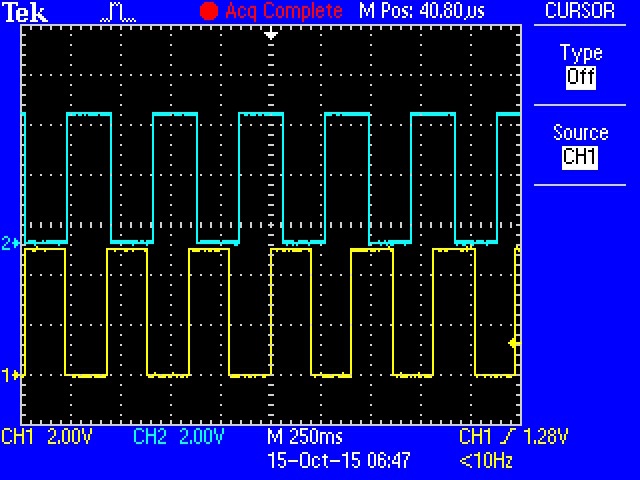
Blue is a little less frequent than yellow.
A Different Structure
Normally, when we add a library to an Arduino sketch, we pick up some new features or functionality, structured for the simple cooperative taking model of Arduino. However, when we use an RTOS, we need to change the way the application is structured.
Let's look at the code above a little more closely, starting at the bottom and working our way up. The new structure will reveal itself.
loop()
//------------------------------------------------------------------------------
// WARNING idle loop has a very small stack (configMINIMAL_STACK_SIZE)
// loop must never block
void loop()
{
}
The loop() function is at the very bottom of the file...and it's empty! The place where we're usually doing the work of an Arduino sketch isn't actually doing any work. As mentioned above, the structure of an RTOS application is very different from a regular Arduino one.
setup()
void setup()
{
  portBASE_TYPE status1, status2;

  Serial.begin(9600);

  // create two parallel LED tasks at priority two
  status1 = xTaskCreate(ThreadLED1, NULL, configMINIMAL_STACK_SIZE, NULL, 2, NULL);
  status2 = xTaskCreate(ThreadLED2, NULL, configMINIMAL_STACK_SIZE, NULL, 2, NULL);

  if ( (status1 != pdPASS ) || (status2 != pdPASS)) {
    Serial.println(F("Creation problem"));
    while(1);
  }
  // start scheduler - should never return
  vTaskStartScheduler();
  Serial.println(F("Scheduler Returned"));
  while(1);
}
Above that is setup(), and there's a little more going on here. Like any regular sketch, this initializes things used by the sketch -- most notably, the two calls to xTaskCreate(...). These calls inform the RTOS of functions that actually do the work. The first parameter of each of these is the name of the routine that implements the timed LED blink, ThreadLED1 and ThreadLED2, respectively. After creating the tasks, setup calls vTaskStartScheduler(). If all goes according to plan, this call will never return.
The LED Tasks
static void ThreadLED1(void* arg)
{
  pinMode(LED1_PIN, OUTPUT);

  while (1)
    {
        vTaskDelay(200);
        digitalWrite(LED1_PIN, HIGH);
        vTaskDelay(200);
        digitalWrite(LED1_PIN, LOW);
    }
}
Each LED is controlled by its own function, ThreadLED1 and ThreadLED2. Aside from the pin it's controlling, and the time values used, these tasks are identical. They configure their respective pin as an output, then enter an endless loop, pausing and changing the LED state.
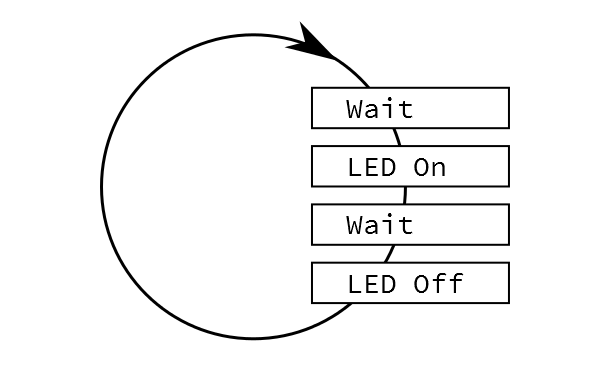
Reading these functions, they are straightforward and understandable: Wait a while, turn the LED on, wait a while again, turn LED off, repeat. The real trick is to make the waiting less expensive.
The whole point of this exercise has been avoiding the Arduino delay() routine. Delay is problematic because calling it keeps the system busy, counting down the specified time. It doesn't do anything else in the meantime. But what if it could?
Instead of delay(), the LED threads call the FreeRTOS function vTaskDelay(). From the perspective of the function, it's pretty similar, but behind the scenes, it allows other things to happen without our LED blink routine having to know about it. When vTaskDelay() returns, the specified time will have elapsed. The xTaskCreate calls told the RTOS about work to be done, and the RTOS figures out when to do it.
You can think of the LED threads as running independently, in parallel. They don't have to worry about anything external. This is a simple example of multitasking, a common feature of RTOS. Adding another LED could be as simple as writing a third function, and starting up a third task.
Going further
Again, there's a lot more going on inside an RTOS than I can cover in one short blog post. Hopefully I've peeled the tarp back far enough that you're ready to explore a bit on your own.
FreeRTOS has a lot of documentation online.
- First, I'd recommend looking over their naming conventions. Their functions and variables look like they're prepended with alphabet soup, but it's actually an application of Hungarian notation, which makes more sense once it's been explained.
- Similarly, there are a number of compiler macros used by FreeRTOS, which are explained here.
- There's documentation of the routines and features of FreeRTOS in their API Guide.
From there, I'd progress through the other examples in Mr. Greiman's library, which demonstrate some different features and instrument some interesting circumstances.
Useful Stuff to Know
Moving from cooperative, single-tasking Arduino to an RTOS involves a different approach to structuring applications. There are bound to be some sticking points.
- The first sticking point is RAM.
- The RTOS approach requires more RAM, as each task needs RAM for its own stack. I generally see this as a small price to pay for being able to write more efficient and better organized code. Moving from the RedBoard to an Arduino Mega 2560 quadruples the amount of RAM, easing that restriction.
- You can also check the amount of free RAM on the system using the
freeHeap()anduxTaskGetStackHighWaterMark()system calls. There's a good example of these in the frBlinkPrint example sketch. - You'll notice that the
F()macro is used on strings in the Serial.print() calls of many examples, so that strings are stored in flash memory, rather than getting copied into RAM when the processor boots.
- The compatibility of existing Arduino libraries needs to be evaluated. Most Arduino libraries use a cooperative-polling approach, which might conceal busy-wait situations.
- An RTOS is a pretty sophisticated piece of code, and as such, it's hard to debug in the Arduino IDE. Serious debugging calls for more serious tools. Atmel Studio 7 adds the ability to create projects from *.ino files. I haven't had time to try it yet...maybe that will be my next blog post.


Awesome post! I have been using freeRTOS for a while, running on an arduino DUE, and i really like it! It has extensive documentation and the forum is very active!
There are a number of example freeRTOS projects for the DUE (cortexM3), so I based my project on one of them and stuck to using a setup with a makefile. I think that this is a good solution for many projects, but it is awesome that freeRTOS now is easily available for the arduino community, the learning curve for my setup was kind of steep... I can not wait to try this library, so many ideas!
This has been on my todo list for months now! Glad to hear it works well! :-)
Could you post the link to what you used for your initial RTOS setup and documentation? Also, did you get it setup with the Arduino IDE or Atmel Studio?
For the initial setup I used Atmel Studio 6, but then exported the project to a normal makefile setup (finding the correct build arguments requred a bit of work). One thing i found frustrating was to get a tool that could upload the binary to the board. I ended up using the bossa binary delivered with arduino IDE. It was somehow different from the other bossa versions I found elsewhere.
I used the freeRTOS website freeRTOS.org for documentation, and I also bought the freeRTOS tutorial book for cortex-m3.
Unfortunately I never used the RTOS analysis tools included in Atmel Studio that you talked about in another comment to this post, but that seems very convenient. Please let us know if you get it working!
Is there a mistake in the code example? I see a line that reads, simply:
#include
Looks like what's supposed to be included is missing...
Wayne
Try
<FreeRTOS_AVR.h>Somehow it fell off in the cut/paste. I'll go fix the example.
A funny effect of intermixing markdown and raw HTML.
The text is correct in our CMS.
Apparently the pointy brackets were being translated as an HTML tag, and not displayed by the page rendering code. I've replaced them with \> and \<, and it seems to be OK.
This is an awesome post, I really loved it. Can wait to get home and put my hands on it. It would be very nice to have more RTOS posts! :-)
I know there's an esp8266 port for rtos (expressif,mattcallow) but does anyone know if it's been made into an Arduino Library like the avr and amd versions here? Is anyone working on that?
Watson, I think I get it. Mind blown. It's like there are threads now on an Arduino and somehow, magically, they all have stacks. Wow. How is that done? I suppose the whole rest of of the program after vTaskStartScheduler() is a series of interupts that schedule more interrupts but I'm still working on how a single cpu stack is managed to do that. Greatest hack ever my vote you have. This means that kids can write simple controllers to run stepper motors in a coordinate way. Robot time. But, I must ask. Will it run two tasks on an Uno R3? 4 tasks?
I got bored after 8 tasks on an R3. Each of those tasks was pretty trivial, not calling any further functions that would put a bunch more on the stack (IE: not calling
printf()). This was using only theMINIMALstack size, which I believe is 100 bytes.The stacks are allocated on the heap when the task is started.
One of the nice things about this FreeRTOS port is that it's distributed as source code. If you want to see how something is implemented, you can go read it. Actually reading it can be a little challenging, though, because it uses several layers of macros to keep it portable, and sometimes you have to unravel a bunch of nested references to find out what something really is (thus my hedge on the actual size of minimal stacks...).
Good discussion. I'm surprised the TimedAction library hasn't come up in this or last week's post. Definitely not an RTOS solution, but it's insanely simple and 'good enough' for many timed task scenarios. It basically abstracts the execution of tasks on a regular period (ms) using only a handful of simple methods.
Energia, the fork of Arduino for Texas Instruments' boards, features the TI-RTOS on the MSP432 and CC3200 LaunchPads.
Learn more at LaunchPad MSP432: RTOS for Everyone and Exploring RTOS with Galaxia on Energia MT.
I would like to see this topic continued! RTOS are used in so many things, you got to start somewhere right :-)
I have been meaning to download Atmel Studio, there is a plugin to include FreeRtos to the IDE with some fancy analysis tools showing the time slicing of the tasks and the simulated load on the processor. It might be worth checking out and writing a article on it :-)
Cool write-up.. it inspired me to take a look into this RTOS in the very near future. Thanks!
Very cool article.. I can see many arduino apps that would benefit from a structure like this.. One question that I'll ask here to maybe inspire a more complex example code, but then probably go just read about myself, is how variables are managed between threads? If thread 1 is monitoring a couple sensors and making calculations, are the variables all global in nature, so they can be monitored, acted upon, or adjusted by the other threads?
This is actually a huge topic in RTOS programming -- big enough that I didn't want to even try to touch it in the post.
You're correct to assume that chaos can ensue if the data is freely accessible by any task. A given RTOS will have a number of features to allow data to safely move between threads. Different types of interaction call for different schemes, and learning how to use them is a big part of RTOS programming. The FreeRTOS structors for this are documented in their Inter Task Communication document.
If the data in question is flowing unidirectionally from the one thread to the other, the monitoring thread could send a message to the other thread when data is ready. Messages can flow through queues (somewhat akin to pipes in unix/posix).
Threads can also send simple binary indications between one another using semaphores -- a semaphore being a more rigorous version of a flag. The frBlink demo sketch has an example of two threads using a semaphore.
If the system is a free-for-all, with multiple threads all trying to read and write the global data, you can protect the data using a mutex, so that only one thread has access to it at a time. In my mind, A situation like this is an indication that the design might need further refinement -- perhaps the data needs a thread of it's own, with a more formal interface.
Wow.. that is pretty mature.. Amazing to think that such things have been ported down to be available on something like an Arduino.. If only there were more hours in the day, I could someday hope to play with all of that!! :-) (where is that winning lottery ticket, anyway!!) Thanks for a great explanation, and all the links!
In multi-threaded programs, the threads share the same address space so global variables can simply be declared and accessed from either thread. It's the simplest approach, but not necessarily a good idea. If both threads are only reading, that's usually OK, but if either is writing that can cause trouble. In that case you have to synchronize the threads' accesses with semaphores and/or mutexes.
In the comments of your example, right before the loop() you have
It doesn't really matter as loop() will never be reached (unless freeRTOS calls it). This is because of two reasons, both in setup(). If vTaskStartScheduler() never returns as expected, then setup() will never return. Even if vTaskStartScheduler() does return, the next line is
which will never end. Thus, because loop() is never reached, who cares what it is in loop(), even if it is blocking? It's just dead code.
Remember, when compiling in the ArduinoIDE, the middleware creates a .h file that enumerates all the functions, and includes main.cpp that contains the following main() function:
So you can see that as far as the C++ compiler is concerned, if setup() never returns then loop() is never reached.
Sorry, after babbling I forgot to finish my thought...
Shouldn't that comment instead read something to the effect of:
Nevermind, see the sub-thread on Byron J's comment. FreeRTOS does call it.
There's one little piece of trickery in FreeRTOS you've missed.
FreeRTOS has some hooks that allow the user to add functionality to the heart of the system. You can read a bit more about it in their Hook Functions page.
This port assigns the
loop()function to the idle task (in FreeRTOS_AVR/idlehook.c). It's not called by the Arduino boilerplate, instead by the scheduler when no other tasks are ready to run.Ah. I didn't go into depth reading about how FreeRTOS works. My bad for not researching before I commented.
I think it's a perfectly fair criticism of the example. Bringing familiarity of Arduino, and reading the example I posted, you reached what appears to be the obvious conclusion.
FreeRTOS under Arduino quickly reaches a point where two very different approaches to structuring applications are coexisting, and we need to understand some of the subtleties of both approaches to get them to work together effectively.
These last two Enginursdays have been great! These topics are a little more on the advanced side, but they are good introductions on how to handle timing issues. These days I default to using a RTOS whenever I'm dealing with multiple events. My 'simple' programs always seem to grow and it's easier to start with an RTOS then to try to manage multiple threads manually.
That's nice, but why not get rid of the Setup/Loop paradigm altogether?
Empty your .ino file and add a .cpp file to your project that has the main() program, this file must have a different name than your .ino file. Four caveats: (1) Your .cpp file(s) must (each) #include <Arduino.h> (2) To use the Arduino timer libraries you must call init() first thing in main(). (3) Your .ino file must have the includes for all the Arduino libraries you are using, otherwise they won't be brought in, e.g., #include <SPI.h> and nothing else, no setup() or loop() (4) To use C++ in all its glory you will need .h files to declare all your classes and functions, and .cpp files for the implementations. This means 2 or 3 times the lines of code over the simplistic Arduino approach, but your executable image size won't increase.
If you are going to go through all that, why stick with the ArduinoIDE? All the hidden middle-end work that the ArduinoIDE does is pointless if you are going to "use C++ in all its glory". May as well us an actual C++ IDE that supports avrdude (either internally or through plugins) and skip using .ino files altogether.
Good article, thanks for your work and research.
This seems like overkill for an 8-bit AVR though. Going down the road of more and more libraries and layers of abstraction, you eventually end up with something that is more complicated than the original starting point. Configuring a timer and ISR in Atmel Studio is no more complicated-looking than the code shown above, and actually teaches the programmer what the AVR is doing behind the scenes. It's the difference between having control over the device, and relying on someone else's abstraction to gain the appearance of control.
You might also considering doing one of these articles on ARM devices and showing off the SysTick timer.
Great article. The first line of code in the example is:
include
Shouldn't there be something included?
Also, what version(s) of arduino does RTOS run on, Uno, Leonardo, Teensy?
From the ReadMe.md on GitHub
"This is a port of FreeRTOS as Arduino libraries. The documentation for FreeRTOS is located here: http://www.freertos.org/ FreeRTOS is version 8.0.1
These libraries were tested with Arduino 1.05 for AVR boards, Arduino 1.5.7 for Due and the 1.20RC2/1.0.5 version of the Teensy 3 software."
I've used it with a RedBoard (Uno equivalent) and ProMini, under Arduino 1.6.5.
I haven't looked any closer at the ARM side of the family, so we'll have to take the readme at it's word.
Good little intro to an arduino friendly RTOS. Although putting one on an 8 bit micro seems like a square peg, round hole situation to me. There is a small error/typo in the paragraph immediately after task image. "The real trick is to make the waiting less inexpensive."
I just published a state machine based framework for Arduino called Automaton that can do this kind of thing very elegantly as well. I guess it could fit your round hole a little better.
Have a look on github if you're interested: https://github.com/tinkerspy/Automaton (docs in the github wiki)
A Sparkfun article on state machines was one of the things that inspired me.
I'd like to run MicroC OS on an arduino. The priority based task structure lends itself well to embedded systems I think.