
If you read my last Enginursday post, you saw that I've been tinkering with Teensy Audio. I'd like to take this opportunity to unveil a what I've been working on since then.
The design files for the whole thing are on GitHub. I'll admit that I've been working quickly, and the repo is somewhat roughshod. This very post is an attempt to document the underlying design!
Hardware Architecture
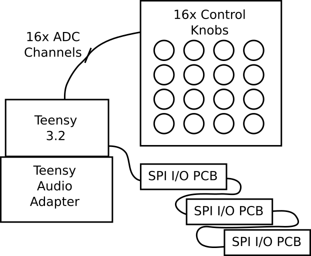
The hardware is fairly simple. The heart of it is a Teensy 3.2 with the Audio adapter. The buttons and LEDs are attached to the processor via the SPI bus, using daisy-chained shift registers. Every otherwise unused ADC channel has a potentiometer on it, for a total of sixteen.
The enclosure is a combination of technologies. The control panels are made from laser-cut acrylic, while the wooden ends were milled with a Shapeoko.
DSP Architecture
The signal processing in TeenyBoom is built out of Teensy Audio modules. They further break down into modules already present in the Teensy Audio libraries, and new ones that were written specifically for this project.
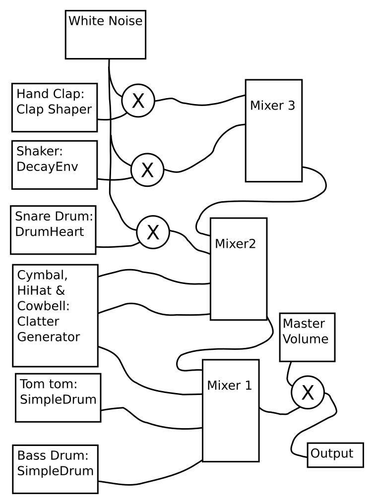
TeensyBoom Voice Architecture
A lot of the "plumbing" is from the Audio library - the filters, white noise source, multipliers and mixers.
Most of the drum-specific tone generation was written for this project based on analog circuit emulation. All of the sound is generated mathematically, and doesn't involve any prerecorded tones.
The bass drum and tom-tom are two instances of the "simple drum" module. The snare drum is a related module that allows white noise to be added in. The hi-hat, cowbell and cymbal share a central module, the Clatter Generator, with design informed by the TR808 cymbal analysis paper by Werner, Abel and Smith. (There's also a related [bass drum]((http://www.dafx14.fau.de/papers/dafx14_kurt_james_werner_a_physically_informed,_ci.pdf) paper, but I didn't discover it until after selecting a different implementation).
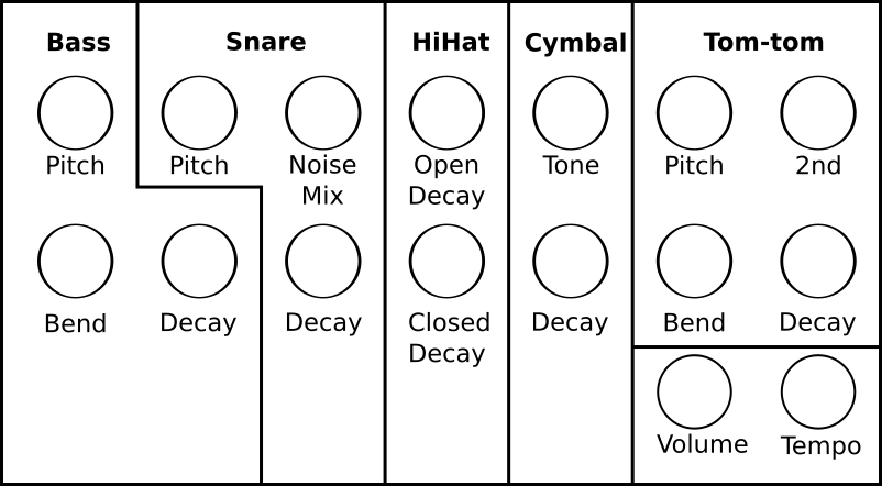
Mapping of controls to voice parameters.
Control over the sound parameters is done with the processor ADC. It reads the potentiometers and updates the corresponding values in the synthesis modules.
Firmware
When I started this project, I had a number of requirements for the software. The basic composition and playback scheme is borrowed from the Roland TR series, with a few additions and improvements.
- I wanted to be able to do most operations without stopping playback. The user can switch between pattern selection and editing without stopping, so compositions can be built up on the fly. The only operations that can't be performed while playing are those that would be destructive to smooth playback, like reading and writing patterns from the SD card, or completely erasing patterns.
- There is a "voice mute" mode that allows individual instruments to be turned off so the user can make variations of a pattern on the fly.
- I borrowed the "pattern chaining" feature from the X0Xb0x. It's an easy way to make patters that are longer than sixteen steps.
The application is written as an Arduino sketch. To keep things organized, it follows a variant of the "Model-View-Controller" design pattern.
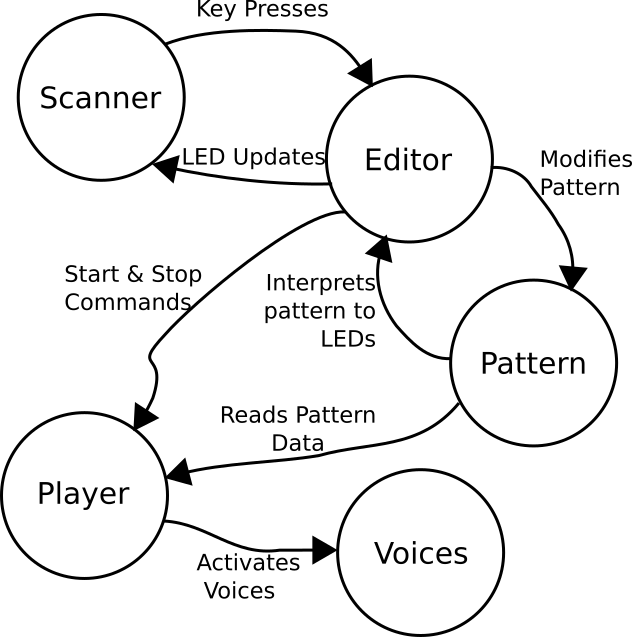
The View is how the system represents data to the user. The LEDs on the control panel are an obvious aspect of this, but they're only a small part of the system. Since the sound generation also delivers information to the user, and is more important and complex, I count it as part of the View.
The Model contains the data in the system. In this case, it is a data structure that represents the Pattern being played.
The Controller gathers input - it's how the user interacts with the model (eventually pushing information back to the view). The user presses the buttons and twists knobs to generate input, which are interpreted into changes in the model and view.
It can be hard to rigidly apply MVC to an embedded system, because the underlying concepts don't always translate (for instance: because they share an SPI bus, my controller input and view output are tightly linked). Still, there is significant value in dividing the work into sensible portions, and partitioning the system into a set of smaller modules. It keeps things organized, making extending and debugging the system easier.
It's easier to determine why an LED is mistakenly stuck on if the LED update code is in an identifiable area!
Large Firmware Projects in Arduino
This is the most ambitious project I've ever written in Arduino. I've stumbled on a couple of issues related to organizing and managing the project.
The biggest issue is relatively simple: the Arduino IDE gets cumbersome if you've got too many files in the project. Once the tab-bar across the top of the Arduino IDE is full, it doesn't handle additional files gracefully. The solution was to create an additional library for the DSP classes. As the signal processing code reaches maturity, it gets moved into the library, where it doesn't crowd the IDE.
The Punch List
While it's in good enough shape to demonstrate, projects like this tend to grow organically: dream up a feature, implement it, repeat until finished.
- Based on my previous success with FreeRTOS, I was hoping to carve the application into a set of FreeRTOS threads. In a casual attempt, it didn't appear that FreeRTOS and the Audio library coexist -- I'm guessing they both use the same timer IRQ. As it stands, timing and tasking in the application are pretty crude, counting milliseconds and triggering tasks.
- The hardware block diagram above omits anything related to a power supply. The whole thing has just been powered from the USB port on the development PC.
- There's no provision for per-voice volume control -- the knobs have been allocated to other functions. I've been considering how to address this. One way would be to add an analog multiplexer and some more potentiometers, but building hardware takes more resources than writing software, so a clever software solution is more likely.
As I said above, it has its own GitHub repository. You're welcome to clone & mutate as you see fit!


Got it working on my Teensy 4. Added MIDI in.
Some great ideas in this project, re: creating custom envelopes and synthesizer classes. I just tried (here in 2020) to build this repo. I think a lot must have changed. For one, the Audio library is now jarred-in to the Teensyduino binaries, so you can't play c++ kung fu with path names like this. I used to say, I have never tried out someone's C++ library without having to override their path definitions.
What does the 74AHC1G126 do on the pcbs?
Nice project! Could you please provide more details about the hardware and software for the button's section?
The buttons & LEDs are tied to the SPI port of the microprocessor using shift registers. A daisy-chain of three parallel-to serial for the buttons, three serial-to-parallel for the LEDs. They're read using an three-byte SPI transaction. It reads the switches, and as a side effect, updates the LEDs.
The switches are on a PCB I designed for the purpose - there are three of the PCB in the system.
Once it's read the three bytes from the registers, it compares the new values to the previous values. If they're different, it sends button pressed messages to the editor routines. The editor routines translate button presses into actions.
If you want more specific details, check the source files -- everything is in the repository. The PCB is under /hardware/, and the software is under /TeensyBoom/. Panel-scanner.h/cpp, editor.h/cpp, and editor-modes.h/cpp are the foundation of the button interface.