Enginursday: I2Considerations
In this Enginursday, we'll explore some of the problems that can creep up when connecting I2C devices

When it comes to microcontrollers, it's easy to run out of IO pins before you run out of programming space. Back in 1982, NXP Semiconductor (formerly known as Philips Semiconductor) came up with a solution called Inter-Integrated Circuit, or I2C. With this technology, designers are able to connect up to 127 devices using just two pins for clock and data. I2C not only frees up I/O pins but also maintains the measurement from the source to the device reading the measurement. With analog outputs, the output is susceptible to noise, which will need to be filtered through hardware or software. Because I2C is digital, noise can often be ignored, but that doesn’t mean it’s problem free, and there are design considerations that need be addressed --- no pun intended.
One of the first things to look at is the speed to communicate between the microcontroller, known as the master, and the device that is being controlled, known as the slave. For Arduino, the Wire library defaults to 100kHz, but depending on the master and the slave device, you could communicate as low as 10kHz (low-speed mode), to as fast as 3.4MHz (high-speed mode). The faster you communicate, the less amount of capacitance is tolerated on the line, due to the increased rise time of signals. The standard maximum capacitance for I2C lines is around 400pF.
What creates the capacitance, though? There is some capacitance from the devices themselves (around 20pF), but the bulk of the capacitance comes from the wires to connect the devices together. On a circuit board, capacitance isn’t that big of a concern, but there is some created just by having the traces run closely to the ground plane. On cables, however, you could create 40--120pF per meter. For example, with CAT5 cable used for wired internet connections, the capacitance must not exceed 50pF per meter. Shielded cable is higher at 114pF per meter.
What does this mean for the real world? I set up a test using two cables. One was 6 inches long, and the other was 6 feet long. In order to see the effect of cable length more clearly, I removed the pull-up resistors that are normally required for I2C communication.

6-inch cable
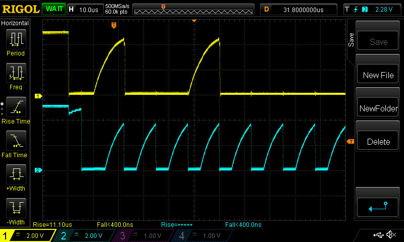
6-foot cable
With the 6-inch cable, the SDA line (in yellow) sort of looks like a square wave with a rise time of 3.8us. In the 6-foot line, however, the data line looks more like a saw-tooth wave than a square wave with a rise time of around 11us. This is a result of the capacitance of the wires, and grounding the other wire of the twisted pair from the CAT5 cable would increase the rise time even more.
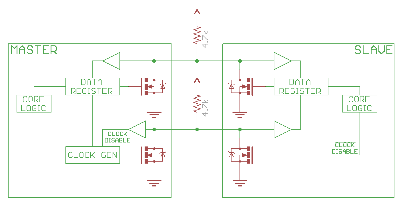
The second half of the design is the pull-up resistors used. I2C uses open-drain technology, meaning that the devices are able to pull the signal down to ground, but are not able to pull the signal high. For that reason, all of our boards that use I2C have pull-up resistors on them. The resistors need to be of a certain value, though. If the resistor value is too high, the rise time of the signals can be too large to be read.
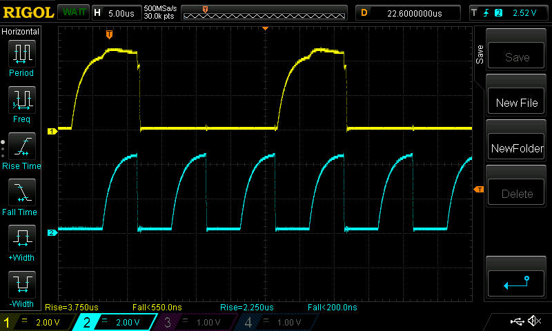
6-inch cable with a 100 kΩ pull-up resistor

6-foot cable with a 100 kΩ pull-up resistor
And if the value is too low, oscillations known as ringing can be large enough that the master or slave devices misread the data on the lines. Too small of a resistor value can also prevent the signals from reaching a low enough voltage to be read as a logic 0.

6-inch cable with 100Ω pull-up resistor
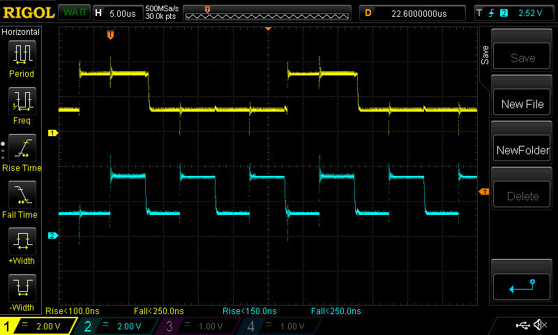
6-foot cable with 100Ω pull-up resistor
Looking at the waveforms, we can see the ringing when the signals switch from low to high, as well as some crosstalk on the data line when the clock line switches. We can also see that when the signal is low, the voltage is around 1.2V. If our sensor were powered off of 3.3V, that voltage could be too high to be read as a logic 0.
Here at SparkFun, most if not all of our boards use 4.7kΩ pull-up resistors. The value doesn't need to be too specific, 1kΩ to 10kΩ would work just as well. With 4.7kΩ, though, you can connect a couple devices together without having to disable the pull-ups. But if you're planning on using a few or more boards on the same I2C bus, make sure you disable the pull-ups on all but one of the boards using a hobby knife.


I'm wondering if anyone could elaborate on why, if using more than a couple of boards, you should disable the pullups on all but one.
It's to avoid the ringing in the clock and data lines as preventing the logic low voltage from becoming too high. With two boards, the impedance becomes 2.35k and with three boards it becomes ~1.57k and so on.
The TMP102 for example, considers any voltage between -0.5V and 0.3*VCC. So with a supply voltage of 3.3V, a logic low is any voltage between -0.5V to 0.99V. In the example where a 100 ohm pull-up resistor is used, the logic low was 1.2V, so the TMP102 would see that as a logic high still.
Great article, but you missed the chance to talk about active terminators for I2C. Active terminators can clean up those slow I2C signals a lot and make a marginal I2C bus rock solid. Even better would be to introduce a new Sparkfun breakout board containing just an I2C active terminator.
That's a good point and you nailed the reason why I didn't test (and therefore mention) active terminators, because we don't have an active terminator that I could test with.
Muy interesante tu articulo