Enginursday: Qwiic Control Panel
How to use Qwiic connectors to make versatile control panels that can control a myriad of electronics projects.

Sometimes the best interface is a physical interface. Buttons, switches and knobs have always been more entertaining to me than typing away at the command line. However, wiring up such control panels can often be quite the task. With a variety of connectors that are becoming more widely used, this task has become much less of a chore. SparkFun's Qwiic connect system is one such ecosystem that allows for easier connections and faster build times. In this post, I will show you how to use a variety of SparkFun parts to create a generic control panel that can be used with a number of projects, all using just four wires!
A while back, I came to possess a rather impressive aquaponic control system after befriending one of the co-founders of Grove, an aquaponics startup based out of Massachusetts. The system came from a first-generation Grove Aquaponic Garden. These gardens sell for a pretty penny, thus the control system was something I was eager to reverse engineer. After finding datasheets for all the ICs on the board, it was time to start piecing it all together.
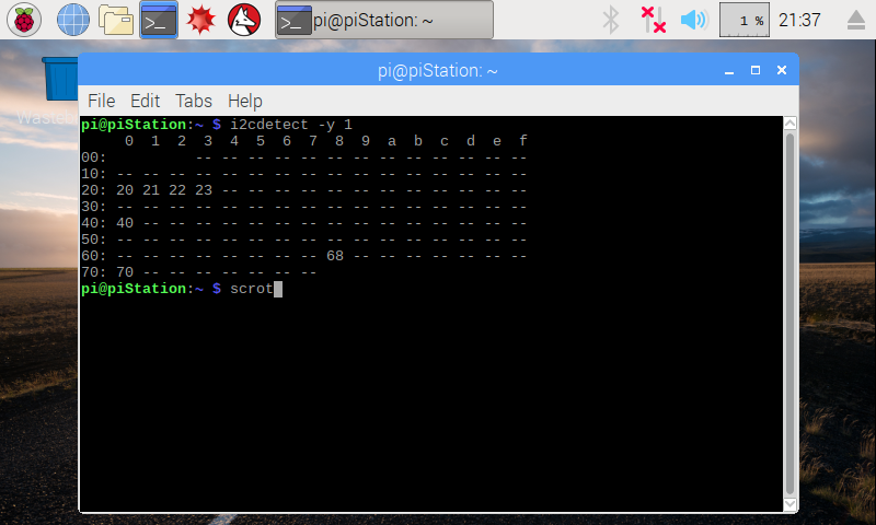
Pro Tip: The Raspberry Pi is a great tool to ping all devices on an I2C bus.
All of the ICs on this board communicate over I2C. There were several of the same I2C I/O expander IC - the MCP23017 - each with a different address set via hardware. It was simple enough to look up each address in the respective datasheet, but it never hurts to have a simpler and more reliable solution. Using a Raspberry Pi, I was able to connect to the I2C lines of the board and ping every I2C device on it. To do so, all you need to do is connect GND, SDA and SCL to the bus you'd like to ping. Make sure you have enabled I2C communication via raspi-config and installed the I2C tools sudo apt-get install -y i2c-tools, then run the following command i2cdetect -y 1 (see this tutorial for more details). Here is a screenshot of the output after running the command on the Pi connected to the Grove board.
With addresses in hand, it was time to start figuring out which peripherals were connected to which I/O pins. After much time with the multimeter, I mapped out each connection. The board contained a variety of inputs and outputs including a handful of relays, LED light controls, a real-time clock module, analog inputs on a number of current sensing ICs (ACS712s), and a number of configurable DIP switches. The main microcontroller for all these peripherals is the Particle Photon. The Photon is my personal favorite internet-connected device. However, when using it remotely, you must have some sort of screen attached if you want to print data rather than sending it to a website or service (you can still Serial.print when it's connected to a computer). To confirm each peripheral was connected to the pin I had mapped, I wrote code that would turn each I/O pin on then off, and print which pin was being controlled to a Photon Micro OLED Shield.
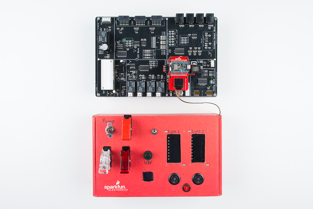
Once I knew which pins controlled which peripherals, it was time to start building my control panel. I went a little crazy with the panel-mount buttons and switches, adding more than I actually needed. My intent was to make this a controller that could be used in any project, with room for growth.
Let's see what's on the inside of the panel!

To control the PWM signal that changes the brightness of the two LED lights, I added two SparkFun Touch Potentiometers. These devices are great when it comes to daisy-chaining multiples together. Their I2C addresses can be changed on the fly, allowing for more potentiometers than you'll likely ever need on one bus. With the addition of a couple Qwiic Adapter boards, connecting them together was a breeze!
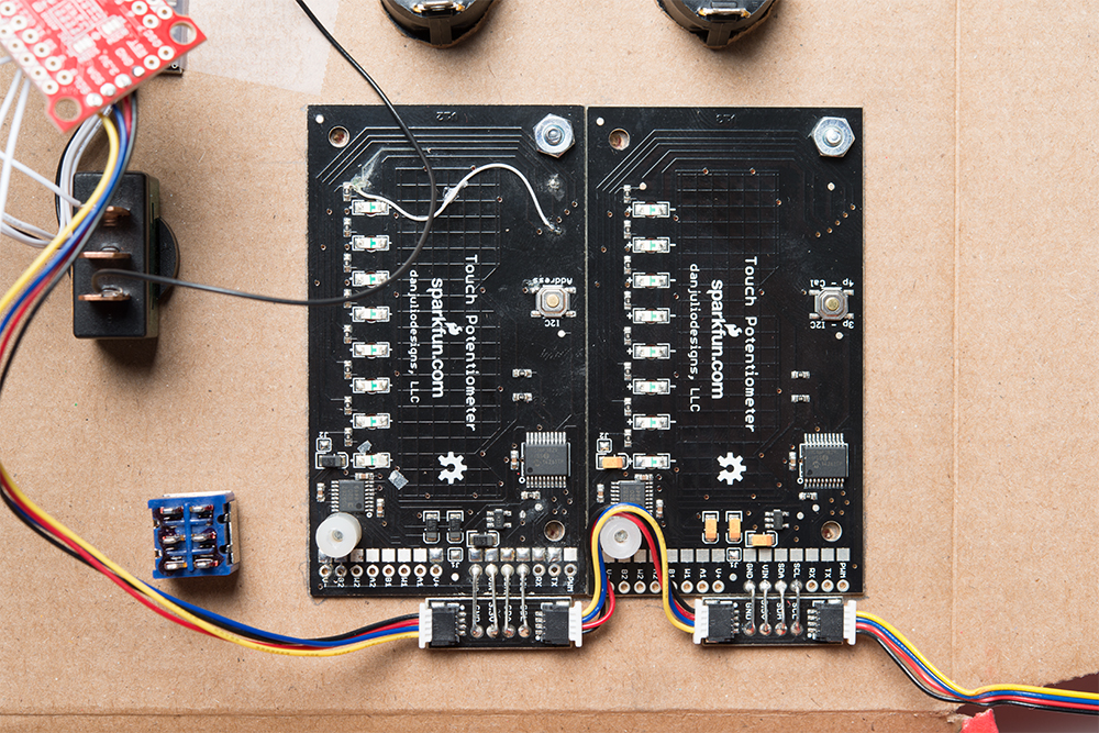
Connected to the touch pots is a SparkFun SX1509 I/O Expander. Just like the MCP23017 IC found on the Grove board, the SX1509 allows you to read or write digital I/O over the I2C bus. Using this breakout, I was able to add all the switches I needed for controlling the relays, which in turn control pumps and other accessories in the system. Rather than connecting Qwiic adapters, I wired some Qwiic cables directly to both ends.

Pro Tip: Though it may be tempting to use the longest Qwiic cables available, it is advised you use the shortest length that will work for your project. I2C communication is susceptible to noise, and keeping the bus short is your best defense.
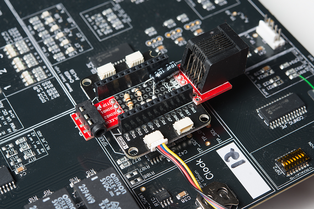
From the SX1509, the I2C bus connects to a Qwiic OLED board. These OLEDs may communicate more slowly over I2C than SPI, but they make up for their loss in speed with their ease to install into a project. They are perfect for displaying data, and having an extra screen came in handy for this project. With this screen and the one on the Photon OLED shield, I can print out a plethora of information. In this case, they were used to print the current being sensed by each individual ACS712, and thus individual and total power consumption of all the peripherals.
Pro Tip: Make sure you keep track of which devices have their I2C pullup resistors enabled, and which don't. Most SparkFun products have a jumper to enable or disable the resistors. If the resistance is too high or too low, you may start to see some loss in signal integrity or get bad data.
Last, the entire panel connects to the Grove board using a Qwiic Shield for Photon. With more new Qwiic products in development, adding sensors, actuators and inputs to a system such as this is about as easy as it gets!
This same control panel can now be plugged into another I2C system and used just as easily to control audio electronics, motors, robots, fabrication equipment and much more! What sort of things would you like to build a control panel for? What components would you like to see added to the Qwiic ecosystem? Let us know in the comments below. Thanks for reading!


