Everything You Didn't Want to Know About RGB Matrix Panels
When SparkFun got a shipment of 1:8 scan rate panels, it fell on me to make them work with the wrong library.

A few weeks ago, SparkFun got a shipment of 1:8 scan rate RGB matrix panels by mistake. We had ordered 1:16 scan rate, because this is the most common panel among hobbyists and is directly compatible with a number of Arduino libraries. When we realized that these panels weren't exactly what we had ordered, we decided to turn lemons into lemonade and write some supporting Arduino code. What followed was nearly two weeks of unspooling and modifying Adafruit's RGB-matrix-panel library. While I reverse engineered Phil Burgess and Limor's excellent work, I learned more than I've ever wanted to know about these types of displays and what it takes to drive them in full color.
1:8? 1:16? What's the difference?
If you're anything like me, it's probably not immediately obvious what's meant by "scan rate" or why it's given as a ratio (or sometimes a fraction). In order to understand you'll need to know a little bit about how these displays work.
RGB matrix panel displays are fundamentally different from other types of panel displays like our Flexible LED Matrix, for instance. Whereas the Flexible LED Matrix is built from a grid of addressable WS2812B LED modules daisy-chained together, the RGB Matrix Panel is actually comprised of standard tri-color LED chips. Each color of each LED is driven by one bit of a shift register and all of the shift registers are then daisy-chained together, allowing you to drive all of the LEDs by clocking in high or low bits for the red, green, and blue LEDs individually. Because the LEDs are driven by shift registers, there is no individual PWM capability and thus these displays are natively 8-color displays. There is a clever way around this that we'll talk more about later.
To better understand how this shift register business works, let's have a look at a simplified model. I've put together an animation of a single color, 4x4 matrix. Take a moment to study that and then we'll walk through the cycle.
It may be silly to drive 16 LEDs this way, but when you start getting into larger numbers it's incredibly helpful. Sure, you could drive all 16 of these LEDs at once, but if you have a matrix of 1024 LEDs you're not going to just clock in all those pixels and latch them out at once because the current consumption would be huge! Instead, the trick is to take advantage of an effect called "persistence of vision" in order to build the image a few pixels at a time by "scanning" your way across the display.
For each row of pixels, we repeat the following cycle of steps:
- Clock in the data for the current row one bit at a time
- Pull the latch and output enable pins high. This enables the latch, allowing the row data to reach the output driver but it also disables the output so that no LEDs are lit while we're switching rows.
- Switch rows by driving the appropriate row select lines.
- Pull the latch and output enable pins low again, enabling the output and closing the latch so we can clock in the next row of data.
If we repeat these steps quickly enough your eyes won't be able to tell that only one row at a time is lit and the complete image will appear on the display. Obviously, the more bits we need to clock in, the more slowly this cycle goes. To address this, RGB panels are built to allow us to clock in the bits for our red, green and blue LEDs at the same time. On our 16x32 displays, data is clocked in 3 bits at a time on 3 input lines. Each clock cycle, then, represents one of the 512 pixels of the display. On larger displays, like our 32x32 display, data is clocked in 6 bits at a time: 3 represent a pixel at the top of the panel and 3 represent one at the bottom. Each clock cycle in this case represents 2 pixels of the display, so to write to the entire display in both cases would take 512 clock cycles. The scan rate, then, describes how many pixels we're scanning at a time. In a 1:16 scan rate panel, we're lighting 1/16 of the pixels at any given time. on a 32-pixel wide display, this is pretty convenient as each of those 16 groups of pixels becomes 32 pixels long, exactly one row.
Taking all of this information together, we can see that the scan pattern for a 32x32 1:16 display looks like this:

In a 1:8 scan rate panel, we're lighting 1/8 of the pixels at a time. For a 32x32 panel that's 2 whole rows. The manufacturers of these panels usually stagger the rows so that "old" pixels don't get grouped together on the display and cause inconsistencies in the image while it's updating. Because of this, the scan rate for 1:8 panels looks like this:

Already, it's easy to see why running a 1:8 scan rate display with code written for 1:16 won't work the way you expect. But there are even more layers to this problem when we want more than 8 colors...
A Rainbow of Planes
The traditional approach to making lots of colors from an RGB LED is Pulse Width Modulation, or PWM for short, and it works really well for a handful of LEDs. The idea behind PWM is simple, you switch the power to an LED on and off really fast and it changes the brightness. If you do this for the three LEDs in an RGB module, you can mix red, green, and blue to different ratios and generate a whole bunch of colors. Unfortunately, using only an 8-bit Arduino running at 16MHz, we don't have enough timers (or indeed time) to keep track of when the red, green and blue components of all 1024 pixels in our panel should be on. The RGBmatrixPanel library uses two clever tricks to get around this problem:
BCM
First, it takes advantage of a technique called Binary Code Modulation, or BCM. Whereas PWM is really only practical using dedicated hardware — like the PWM capable pins on the Arduino — BCM is much more economical. This is because unlike PWM, which uses a number of interrupts to maintain a fixed frequency, BCM takes advantage of the nature of binary numbers to alter the duty cycle of an output pin. Consider a 4-bit number in binary: Starting from the least significant bit and moving left, each number place doubles in value from 1 to 8. If you assume that value to be the length of a delay then you wind up with a 4-bit number that describes 15 "time-slices," starting from 1 slice at the least significant bit, then 2 slices, then 4, then 8. These slices can be mixed and matched to whatever duty cycle you need. If you consider that having no slices is a valid state, you wind up with 16 possible duty cycles. For instance, if our 4-bit number is 0101, it represents a 5/16 or 31% duty cycle. Because we're switching the state of our LED at fixed intervals, the BCM method requires a fixed overhead for any number of outputs at a given precision. This makes BCM very attractive for situations where you either need to spend your clock cycles carefully or you need to be super fast, both of which apply here.
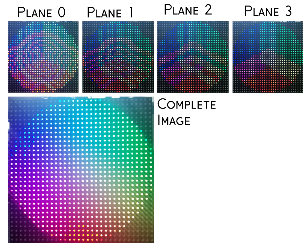
Image Planes
The second trick, in a way, is a natural extension of the first. Because we need to modulate entire rows of LEDs at once, we need to decide ahead of time which LEDs in each row will be lit during each of our "time slices". Basically, we're going to create four image buffers, each of which essentially contains an 8 color version of our image that represents which color channels need to be on during that "bit" of the total time-slices. As we count up through the 16 states that our BCM can be in, each of the four bits will correspond to one of these buffers or "image planes".
Building a Buffer
So how do we arrange all of these image planes in the buffer so that we can write them out to the panel as quickly as possible? Well, there are probably a few different ways to do it, but the way that it's done in the RGBmatrixPanel library is as follows:
The images themselves are made using the adafruit_GFX library which is included as a dependency to RGBmatrixPanel. That library takes care of things like rendering text and geometric primitives as well as assigning colors. Whenever that library wants to interact with the RGBmatrixPanel library, it does so using RGBmatrixPanel's version of the "drawPixel" function. This is the function that knows how to split each pixel into four planes and pack them into the buffer. Because each plane is 6-bits (two 3-bit values for each clock cycle, because we write to the top and bottom of the display at once) and because we need to store four of these planes per pixel, we use a packing scheme wherein each pixel is represented by 3 bytes. The six upper bits of byte one is plane one, the six upper bits of byte two is plane two, the 6 upper bits of byte three is plane 3. Finally, the unused lower two bits of all three are used to store plane 0.
Now, we could line up these 3-byte packages one after the other across an array and call that our buffer, but let's take a moment to examine how this data is going to be read. Remember that we're going to clock out an entire row of pixels from the same image plane before moving on to another. Doesn't it then make more sense to line up all of the "plane 1" bytes for the whole image and then all the "plane 2" bytes, etc.? Well, that would imply that we're going to update the entire image plane at once, which would work fine for still pictures, but if we want to do animation then we could run into problems with "tearing." Effects like this become much less noticeable when you update only one row at a time and then move on to the next. So let's line up all of our "plane 1" bytes across one row and then all of the "plane 2" bytes for that row, etc. Now we just rearrange our buffer to look like this:
In the case of the 1:16 scan rate displays, a "row" is 32 pixels and so it really is a single contiguous row of the display. This makes writing our buffer data out to the display very straightforward from here. We just step through each row and clock out every image plane for the correct amount of time. For plane one, we just push the upper six bits to the port of our controller that the row select pins are on. Do this for each pixel in row one and we're done! For plane two, we do the same thing but now we've started where we left off in the buffer, which is the first pixel plus the length of a row, so we're now clocking out "plane two" bytes. Then the same with plane 3. Plane zero requires a little more effort as we need to reconstruct it from the lower 2 bits of the three previous bytes. Luckily, since we're using BCM, we can arrange our planes so that plane three has the most time slices thus covering for the time plane 0 needs to get rearranged.
If this is still a little bit confusing to you, you're not alone. It took me about a week and a half to wrap my head around this. It may help to kind of "zoom out" and look at the buffer this way:
Or possibly even this way:
If I haven't lost you yet, follow me a little further and we'll go over the changes I had to make for all of this to work for our 1:8 scan rate displays...
Changing Stuff! (or "Rows by any other name")
Instead of dragging you through my changes to this library chronologically, as I figured out what worked and what didn't, I'm going to see if I can describe logically how I got to where I am. Let's start by outlining the technical differences between the 1:16 panels that the library was written for and the 1:8 panels that I had to get flashing.
- Fewer, longer strings of LEDs. This means that each time we increment the row selector, we need to clock out 64 pixels and not just 32.
- We only need 3 row selector pins now because each "row" is twice as long so we now have 2^3 rows.
- The order of the pixels on this display is a little weird in an effort to avoid image tearing.
Each of these major difference required its own hack, so let's address them one at a time... oh, but let's do it in reverse order because I think it will make more sense:
Weird Scan Order
Remember this animation from earlier? It shows the order that rows are addressed on a 1:8 scan rate display:
It looks very straight forward but what it doesn't show you is the pixel order, or in other words, the relationship between a pixel's location in the buffer and its location on the panel. You might imagine that as you clock in pixels, they fill up all 32 slots in the first row and then, based on this animation, they fill up all 32 slots on the eighth row — and this is what they do — just not precisely in that order. In reality, they fill up the first 16 slots of the first row, then it jumps to the eighth row and fills all 32 slots before jumping back up to the first for the last 16 before moving on to the second row. This diagram shows the physical position of the first 64 pixels in the buffer:
So if we don't want our image to get scrambled on its way to the panel, we need to "reverse scramble" it first! We could do this by transforming the entire buffer but it would be hard to guess when is the right time to do that, since we don't necessarily write over the entire buffer every time we draw pixels. Instead, I opted to create a mapping function that transforms a pixel position received from the adafruit_GFX library into the appropriate "reverse scrambled" pixel position in the buffer. This was achieved using a pair of arrays which I constructed by mapping the target x and y positions of every pixel in the buffer according to their respective positions as reported by the GFX library. To get a "reverse scrambled" pixel location, you use the x and y positions from the GFX library to get the variable at position (y * 32 + x) in the array. There is one array that contains x coordinates and one for y coordinates. Together, these allow us to write our pixels to the correct locations in the buffer.
Row Selector Pins
Even though — physically speaking — our 1:8 display has the same number of rows as our 1:16 display does, electrically it only has half as many. This means if we leave the timing of the 1:16 library intact, we'll get strange errors as it counts from 0 to 15 on the four row select output pins but our display is only listening to three of them. Luckily, this is a very minor fix as the RGBmatrixPanel library is designed to work with 32x32 as well as 16x32 1:16 panels and so there's already a conditional expression that controls whether it continues counting when it reaches 7 or just starts over. All we need to do is make sure that conditional never forks in the "keep counting" direction. In my case, I did it by removing the conditional branch entirely. No problem.
64 Pixels per Row
This part turns out to be the most confusing of all, and could probably be avoided by properly rearranging the buffer. But here we are and this is what I was able to get working so...
In a 1:16 display, a physical row is the same as an electrical row. That is to say, if we clock out 32 pixels and advance our buffer pointer each time then we land on the start of that row in the next plane. Once we've worked through all of our planes, we land on the start of the next row. Our pointer is always where it needs to be simply by incrementing as we write out our bytes. In the case of the 1:8 displays, however, it's not so simple.
Speaking of simplicity, the fact that electrical rows and physical rows are different is going to get confusing. Let's call the physical rows on the display "lines" instead.
We need to write out pixels, but remember that our planes are divided into groups of 32. If we simply clock out 64 pixels in a row, we'll end up clocking out the first 32 pixels of line0/plane1 followed by the first 32 pixels of line0/plane2. What we need to do is to clock out 32 pixels and then increment our pointer past the line0/plane2 and line0/plane3 data and then continue clocking out the following 32 pixels (which will be line1/plane1). This will land our pointer, however, on the beginning of line1/plane2, which isn't where we want to be, so we need to decrement the pointer back to the beginning of line0/plane2. Finally, when we're ready to move to the next row (line 2) our pointer will be at line1/plane1 so we'll need to increment again to skip over the entirety of line 1. To get a better feel for how this works, let's unroll some of the code.
When our pointer is at zero, our first job is to clock out plane 0. This plane needs to be reconstructed from the lower 2 bits of three separate bytes so we construct our byte using left-shifts, ORs and bit-masks and then assign it to DATAPORT. That variable is actually defined as the output port that the row select pins are connected to, so as soon as we assign a value to it, the pin states on the microcontroller change.
As you can see in the code below, we start at the current pointer position (ptr+0) and go to ptr+32, then we skip to ptr+96 and clock out pixels until ptr+128. Because this is plane 0 and we're mixing and matching bits from all over the place, we don't actually advance the pointer, because we want plane 1 to pick up at the current address.
for(uint8_t i=0; i<32; i++) {
DATAPORT =
   ( ptr[i]    << 6)         |
   ((ptr[i+32] << 4) & 0x30) |
    ((ptr[i+64] << 2) & 0x0C);
  SCLKPORT = tick; // Clock lo
  SCLKPORT = tock; // Clock hi
}

for(uint8_t i=96; i<128; i++) {
DATAPORT =
   ( ptr[i]    << 6)         |
    ((ptr[i+32] << 4) & 0x30) |
    ((ptr[i+64] << 2) & 0x0C);
  SCLKPORT = tick; // Clock lo
  SCLKPORT = tock; // Clock hi
}
The other three planes are a little more straightforward because we don't need to construct our output from bits of other bytes. Let's take a look:
for(uint8_t i=0; i<32; i++) {
  DATAPORT = ptr[i];
  SCLKPORT = tick; // Clock lo
  SCLKPORT = tock; // Clock hi
}

for(uint8_t i=96; i<128; i++) {
  DATAPORT = ptr[i];
  SCLKPORT = tick; // Clock lo
  SCLKPORT = tock; // Clock hi
}

buffptr = ptr + 32;
if(plane == 3){buffptr = ptr + 128;}
Here, we clock out pixels from the current address to ptr+32, then skip to ptr+96 and clock out through ptr+128, just like in plane 0. There are a few differences this time, however. First off, we can write each byte directly to DATAPORT since it's pre-composed in the buffer. Secondly, we advance the pointer 32 bytes for each plane so that we will continue to move through the buffer and not clock out the same row over and over. Finally, if we're clocking out plane 3, we make sure to increment the pointer 128 bytes when we're done. This is to skip over the line that we've already clocked out by jumping ahead 96 bytes between for loops.
The original library optimized the code for planes 1-3 quite a bit by writing them directly in assembly language to take advantage of an instruction that allows a pointer to be incremented after it's loaded. The compiler didn't recognize the opportunity to use this instruction, so the programmer forced the compiler to implement it, saving precious clock cycles. After playing with it a little bit, I decided it was a lot of squeezing for not much juice, especially after you add our goofy logic to jump the pointer around all over the buffer.
Speaking of timing, there are a few places in the code where timers are configured or referenced and it's worth taking a quick peek at them. First of all, we have the chunk that sets up the interrupt which will trigger the updateDisplay function:
  // Set up Timer1 for interrupt:
  TCCR1A  = _BV(WGM11); // Mode 14 (fast PWM), OC1A off
  TCCR1B  = _BV(WGM13) | _BV(WGM12) | _BV(CS10); // Mode 14, no prescale
  ICR1    = 100;
  TIMSK1 |= _BV(TOIE1); // Enable Timer1 interrupt
  sei();                // Enable global interrupts
}
The most important line here is where they set ICR1, which is the Input Capture Register. In this case, however, that register stores the top value of the Timer1 counter. In other words, they've set up an interrupt that fires every time that the Timer1 counter reaches the value in ICR1. This value, then, determines the frequency of our updateDisplay interrupt and we'll be updating that variable as we switch planes in order to achieve proper BCM timing.
Next, we have some magic numbers that are used to calculate the new ICR value for each image plane. These numbers are CALLOVERHEAD — the number of ticks between when the interrupt fires and when the updateDisplay function actually starts running — and LOOPTIME — the number of ticks spent inside plane 0. These were apparently measured and then some extra wiggle room was added to account for compiler differences. The changes that we made to the code won't affect the CALLOVERHEAD duration, but the LOOPTIME duration is probably about double (the published version of my 1:8 hack for Adafruit's library indeed doubles this value from 200 to 400) because we need to clock out twice as many pixels per row.
The new ICR value (or the interval before we write new pixels to the display) is determined by doubling the CALLOVERHEAD value (to account for the time it takes to get into and out of the interrupt function) and adding it to the LOOPTIME value. Then, for each successive plane, we double the LOOPTIME value in order to establish our BCM timing wherein each plane from 0 to 3 is displayed for twice as long as the last.
With those changes made, the library will now drive 1:8 scan rate 32x32 displays. Hooray! But it still needs to be published and that turned out to be a little weird as well...
Credit Where Credit is Due
Generally speaking, whenever you add new functionality to an existing open source library, you should contact the author and suggest they pull your work into their original library. In this case, that would entail filing a pull request to the Adafruit GitHub repository. One stipulation of a proper pull request, however, is that your additional features don't break the existing feature set. In other words, I would need to expand the RGBmatrixPanel library to accept an argument switching it into 1:8 scan mode. Furthermore, for the sake of completeness, I would need to preserve the ability to operate both 32x32 and 16x32 panels at both scan rates. Because of the way the library is structured, this would require considerable alterations that might stretch the scope of what it was written for. I decided that the best course of action was to distribute the modified library as a separate utility specifically for driving 32x32 1:8 panels.
It would be disingenuous, however, to publish this as a brand new library because it's essentially an alteration of the RGBmatrixPanel library. Adafruit's RGBmatrixPanel library is released under a BSD license which contains no stipulations for derivative works but keeping in the spirit of FOSS, it's always best to give attribution at the very least. In this case, I opted to treat my derivative work as if it were a redistribution and I left their entire copyright notice intact — with minor alterations to avoid confusion about its compatibility with their products. I added to it a section explaining my alterations and reaffirming the BSD license. The MIT license is SparkFun's permissive license of choice, but the two are roughly equivalent depending on which version of the BSD license you're talking about. Here is the added section, an homage to the era of ASCII Artpacks:
/*

  /$$$$$$                                /$$       /$$   /$$
 /$$__  $$  HAXX0RD FOR 1/8 SCAN RATE   | $$      | $$  / $$
| $$  \__/  /$$$$$$   /$$$$$$   /$$$$$$ | $$   /$$|  $$/ $$/
|  $$$$$$  /$$__  $$ |____  $$ /$$__  $$| $$  /$$/ \  $$$$/
 \____  $$| $$  \ $$  /$$$$$$$| $$  \__/| $$$$$$/   >$$  $$
 /$$  \ $$| $$  | $$ /$$__  $$| $$      | $$_  $$  /$$/\  $$
|  $$$$$$/| $$$$$$$/|  $$$$$$$| $$      | $$ \  $$| $$  \ $$
 \______/ | $$____/  \_______/|__/      |__/  \__/|__/  |__/
          | $$ BY NPOOLE, SPARKFUN ELECTRONICS 2018
          | $$
          |__/

          NOTES:

          - THIS IS A DIRTY HACK TO MAKE THIS LIBRARY PLAY
            NICE WITH 1:8 SCAN RATE 32X32 MATRICES
          - I BROKE IT SO BAD FOR EVERYTHING ELSE THAT I'M
            RELEASING IT AS A STANDALONE LIBRARY INSTEAD OF
            TRYING TO SHOEHORN IT BACK INTO THE 1:16 LIBRARY
          - THE ORIGINAL WORK IN THIS LIBRARY WAS BEAUTIFUL
            AND CLEVER, I'VE UNDONE SOME OF THAT WORK SO
            THIS HACK MAY NOT RUN AS QUICKLY OR SMOOTHLY

          CHANGES:

          - ADDED TRANSFORMATION TABLES TO REARRANGE PIXEL
            COORDS FOR THE 1:8 MATRICES' WEIRD LAYOUT
          - CHANGED THE DISPLAY UPDATE FUNCTION TO WRITE
            OUT 64 BYTES PER SCAN. BECAUSE THE BUFFER IS
            STILL ESSENTIALLY 32 BYTES "WIDE," THE FUNCTION
            WRITES 32 BYTES, SKIPS AHEAD 96 BYTES, THEN FALLS
            BACK 64 BYTES. EVERY FULL CYCLE OF THE IMAGE
            PLANES, WE SKIP AHEAD TO THE NEXT ROW BY
            ADVANCING 128 BYTES.

          ADVERTS:

          - 1:16 SCAN RATE RGB MATRICES FOR USE WITH THE
          UNMODIFIED LIBRARY ARE ALSO AVAILABLE HERE:
          https://www.sparkfun.com/products/14646
          - 1:8 SCAN RATE RGB MATRICES FOR USE WITH THIS
          HACKED LIBRARY WILL BE AVAILABLE FOR A LIMITED
          TIME HERE:
          https://www.sparkfun.com/products/14633
*/
If you think that I'm wrong about 1:8 compatibility being out of scope for the RGBmatrixPanel library, I won't be at all bothered if you use the information outlined in this post to write a properly integrated library and submit a pull request of your own!
"Congration. You Done it."
Well, there it is. That's what it takes to drive an RGB LED matrix panel. Luckily, there are people out there doing the really heavy lifting and all that mere mortals like you and I need to do is install their libraries. With any luck, this blog post will be a trail marker for other people who are hacking on these displays, I tried to build the resource that I wish I had found. In the interest of being thorough, here are a few links:
- Buy one of our 1:8 panels while supplies last
- ...or grab one of our 1:16 panels
- Repository for the Altered Library (for 1:8 scan rate)
- Repository for Adafruit's RGB_Matrix_Panel library (for 1:16 scan rate)
- Very Good Article about BCM for LEDs
Happy Hacking!

Interested in learning more about LEDs?
See our LED page for everything you need to know to start using these components in your project.


I’ve got to say this is the best description and explanation I’ve seen on led matrices. Actually, this one of the best article I’ve read on Sparkfun period. The graphics really drive the points home. Nick must have spent some time on this. It’s also great timing for me as I just picked up a case of 12 64x64 1:32 matrix panels. Although I knew the basics, the discussion on BCM, planes, and buffers really gave me insight to the driver.
Thanks Nick! - Tim
Thanks, I'm glad it was helpful! Good luck with your case of panels!
Hi Nick, have you read my comment? I really need your help.
Please give me a feedback.
Thanks Nick.
Hi! I really appreciated your explanation, it has helped me a lot to control a led panel by myself and to modify the adafruit library to make it work with a 16x32 panel with a 1/4 scan rate. I found a little mistake in the plane 0, blue an green are stored in the 2 first bits of plane 1, red is stored in the second bit of plane 2 for the top display, and blue is stored in the first bit of plane 2 and green and red are stored in the 2 first bits of plane 3.
TOP display Plane 1 |B|G|R|B|G|R|tB|tG
Plane 2 |B|G|R|B|G|R|tR|bB
BOTTOM display Plane 2 |B|G|R|B|G|R|tR|bB
Plane 3 |B|G|R|B|G|R|tG|tR
Hi! excellent explanation Nick! Now I understand many things about how this panels work. Unfortunately I am not a C++ programmer and I can´t modify the library to adapt it to my needsI
Dear member #1541733, I want to know if you are interested in share your modified files, I have a 16x32 1/4 scan panel too but Im having problems to make it work, I found at arduino´s forum someone who modified the Adafruit´s library too to work with 1/4 scan but it only partially works for me, the issue is the "y" axis is wrong on both rows of the panel, for example, if you draw a pixel at x=0, y=0 it appears at x=0, y=4, on the other hand if you draw the pixel x=0, y=4 it appears at x=0, y=0 and is the same with the lower row, if you draw a pixel at x=0, y=8, it appears at x=0, y=12 and if you draw a pixel at x=0, y=12 then it appears at x=0, y=8.
If you write some text the letters are cutted by the half.
The module has printed this model: YLR-P10RGB-3535-4S-V3.3
I hope you can help me, it will be really appreciated.
Thank you :-)
Alberto
"The scan rate, then, describes how many pixels we're scanning at a time. In a 1:16 scan rate panel, we're lighting 1/16 of the pixels at any given time." If what you say is true, we need to lighting 256 LEDs each time on a 64x64 1/16 panel (64x64/16 = 256), but we still lighting 2 rows and 128 LEDs. I am currently experiencing the same problem with a 64x128 1/32 panel. I can't find how many lines are lighting each time. I think Nick should explain the scan issue a little more.
Hi Nick, Thank you very much for this blog. It explains very much about the RGB matrix panel, which I have never ever heard about, previously. Thanks a lot for the descriptive explanation.
Like you, I have a 1:8 scan rate, 32x32 RGB matrix panel. So I am using 'RGBmatrixPanelHalfScan' library. While testing 'testshapes_32x32.ino', I found some malfunctioning so I tried drawing just a pixel using matrix.drawPixel() API.
For matrix.drawPixel(0,0, matrix.Color333(7, 7, 7)), it draws a pixel on LED Panel location (0,8) & an extra pixel on location (0,9). This scenario with different values is explained in this image. Please go through it & let me know what should be the issue with my setup.
If you have any doubts regarding my question, please feel free to ask me.
Nick may help you out, but as a heads up (in case you don't get a response from him)... we don't offer consultation services on custom code.
That being said if you have a bunch of panels and you are using the same connections and code, but not all the panels respond the same... it sounds like some of those panels aren't the same.
What is the BCM abbreviation to expansion. Bit Count Monitoring or another etc . what ? I want to extensive research, but always find healt information as body and heart . Or can you send a link .
The information conflicts with the adafruit library or wrong. adafruit library save data
|Bb|Gb|Rb|Bt|Gt|Rt|P0d|P0d|
small b = bottom, small t = top , P0d = Panel 0 data;
So , According to adafruit, first side 8bit (left side 3 bit) down-row section data, then (right) upper-section-row data. sample. if you want to turn on the first led red at the top of the panel ,you should type -> 00000100. If you want to turn on the first LED of the down-row section in red, you should type -> 00100000.
and Plane 0 data ordering false (for adafruit library).
plane1 data |x|x|x|x|x|x|P0bBd|P0bGd|
plane1 data |x|x|x|x|x|x|P0bRd|P0tBd|
plane1 data |x|x|x|x|x|x|P0tGd|P0tRd|
P0bRd = Plane 0 bottom Red databit
P0tBd = Plane 0 top Blue databit
Other side ; excellent explanation Nick! thank you. Because this information , made me understand RGB panels. like that, I even started to find mistakes. :) :)
I don’t understand the explanation for scan rate. Is it the ratio of the number of LEDs lit in parallel (simultaneously) to the number of LEDs on a row?
So 1:8 on a 32x32 matrix means 4 pixels lit across 32 columns?
Nick goes a little further into the details, later on, but this is the general idea of the scan rate.
Nick, 100 kudos to you for writing this. I thought I mostly knew how those panels worked, but your page does a fantastic job explaining the details.
Hello
You are my Matrix-Hero. I have also a 1:8 scaled Matrix. When i use your librarie. I have 8 blocks. But not on the corectli Position. what i can do? Have you an idea?
Thanks a lot
Patrick
Beautiful and clever explanation and coding, I can't imagine that I can do what you did Nick.
I have try to hack for 32x64 1:8 so bad, but still nothing.
I need the 32X64 1:8 so bad...
Can you help me Nick?
I will pay for your effort if necessary...
Hoping to hear for your reply Nick.
Thanks...