Thirty Years of Test Controller Design Progression
Guest author Kelly Small shares his experience with the evolution of test controllers from the 1980s through today.

Pete Lewis here! This blog was written by a guest author, Kelly Small. We really appreciate his contributions to our community, and are very excited to help spread his extensive knowledge here on our homepage. The conversation about testbed design has been a great one, and if you'd like to read more about SparkFun's own testbed design history, please check out our previous posts here:
And now, onto the amazing story that covers more than thirty years of testbed progression in Kelly's career. Enjoy!
Working as a test engineer for many decades, I have seen remarkable changes and advancements in the field of electronics. My job is to develop test systems that our factories use to verify our products are built correctly and function as expected. These products include everything from a simple cable to a complex module composed of multiple PCB’s with as many as 16 layers. The circuitry can consist of multiple processors, FPGAs and complex analog systems.
Test Architecture
To test our products, which we refer to as UUT’s (Unit Under Test), our test flow consists of several steps. The first test step is in-circuit testing (ICT), where all the UUT’s are tested with a fixture that presses pogo pins into test points on the board, and makes test measurements of all the components on the board. This type of testing can weed out a lot of possible problems with the UUT, such as solder bridges and open runs, as well as wrong parts, missing parts or bad parts.
The next step is programming stations that program unique information into each UUT, such as serial numbers and MAC addresses. Next are the functional testers, which vary somewhat with the product, from a simple bench test to environmental tests, which use a chamber to rapidly heat and chill the UUTs while electrically testing its functions.
While the ICT testers are commercial systems that are purchased and installed at the factories, most of our other test systems are designed, programmed and built within our test engineering group. The heart of these various testers is what we refer to as a test controller. The test controller is a standalone embedded platform that controls power, input stimulus, output measurements and communication with the UUTs being tested.
The Test Controller
Around 1985, we developed the first test controller to support functional testing of a new product line, which included I/O modules of various types. These included Digital Inputs, Digital Outputs, Analog In, Analog Out and others. Modern test systems would most likely be comprised of a PC with a host of data collection modules, but in 1985 very few PCs existed. Those that were in use were 8-bit XT systems with very little in the way of hardware and software for test purposes. We selected the Intel 8051 microcontroller for the brains of our test controller, which has very few peripherals on board. The rest of the kernel consisted of a 32KB SRAM and a 32KB EEPROM. This EEPROM is where the code was stored, typically a 27C256. This chip was programmed one time and then you had to use a UV eraser to erase the chip before you could program it again. This erase process took 20-30 minutes, so you wanted a tube of chips on hand to make constant code changes during a debug session. The rest of the electronics were a group of I/Os used for connection to the UUTs being tested.
- 21 digital outputs
- 8 digital inputs
- 16 analog inputs with 12-bit resolution
- 8 analog outputs
- On-board power sources +5, +15, -15, +24
- 24-volt power supply, adjustable from 10-24 volts
- 2-channel RS-485 ports running 375KBaud
- 1 RS-232 port that communicates with a PC
This group of I/Os is referred to as the common electronics; the intent was to use it as a starting point for each test design and add additional circuitry (point logic) as needed.
The test controller is connected to a PC via the serial port, but while the test controller runs the test sequences, the PC is only used to monitor test operation and report test results to the human operators. As mentioned earlier, PCs were uncommon and very expensive, so one PC was connected to 10 test controllers, and each test controller was capable of testing eight UUTs. This allowed one PC to monitor testing of up to 80 UUTs at the same time.
The test controller was built on a 9”x11” PCB, with a pair of 96-pin DIN connectors at one end.
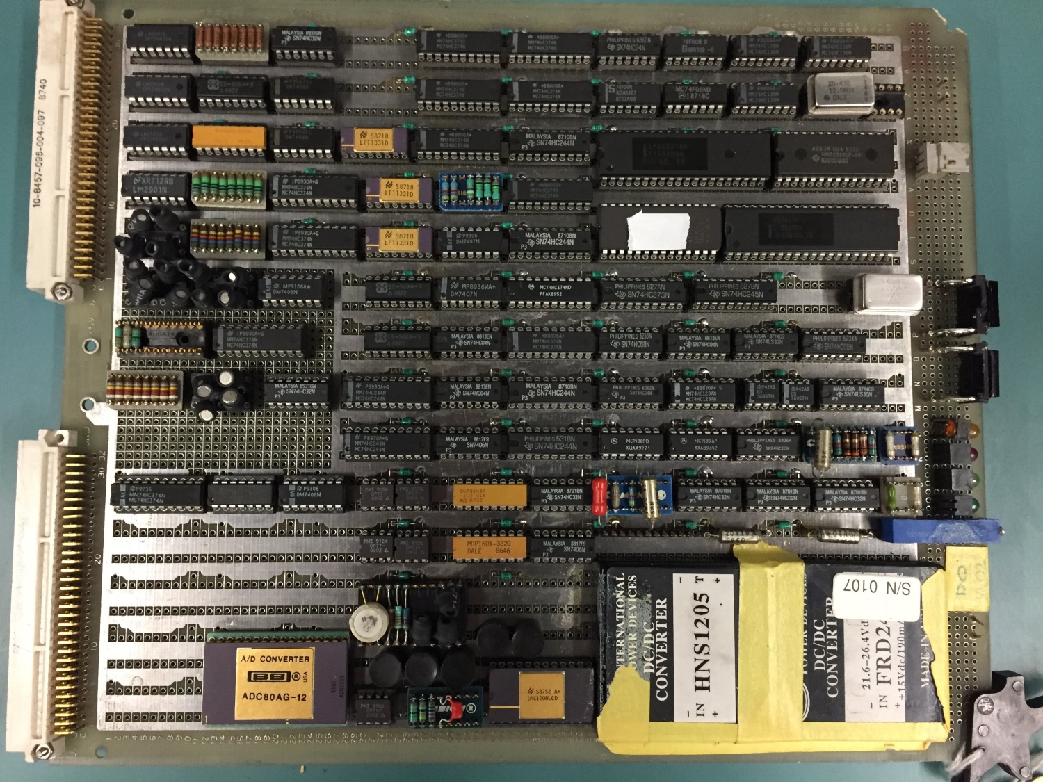
From 1986, the first test controller (top side view)
This first test controller, shown above, had an 8051 kernel and no programmable logic!
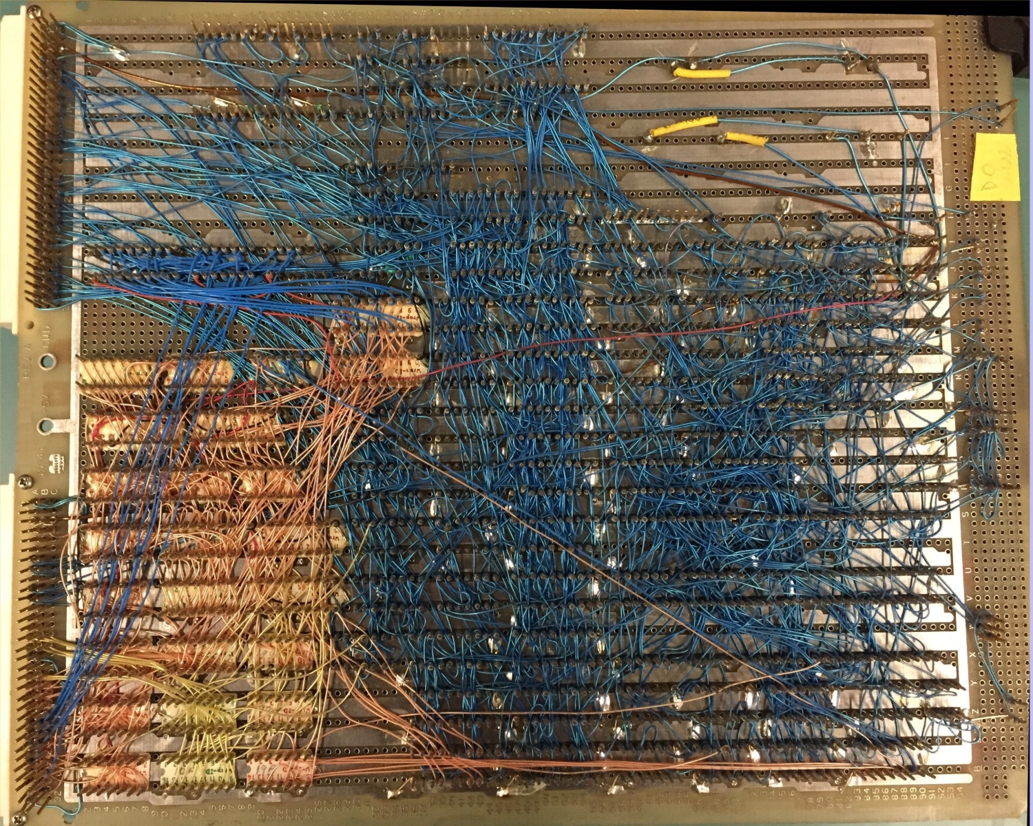
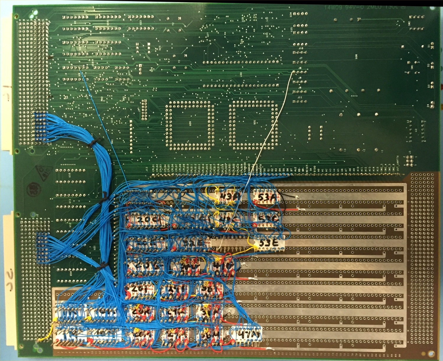
From 1986, the first test controller (bottom side view)
As you can see in the picture above, all of the connections were made with 100 percent wire-wrap.
Around 1987, we created a new PCB that had all the common electronics in a copper artwork section, while the rest of the board was laid out to support wire-wrapping of .3” DIP sockets for the point logic. This reduced the amount of wire-wrapping by a considerable amount.

From 1988, the test controller with "copper artwork section" (top side view)
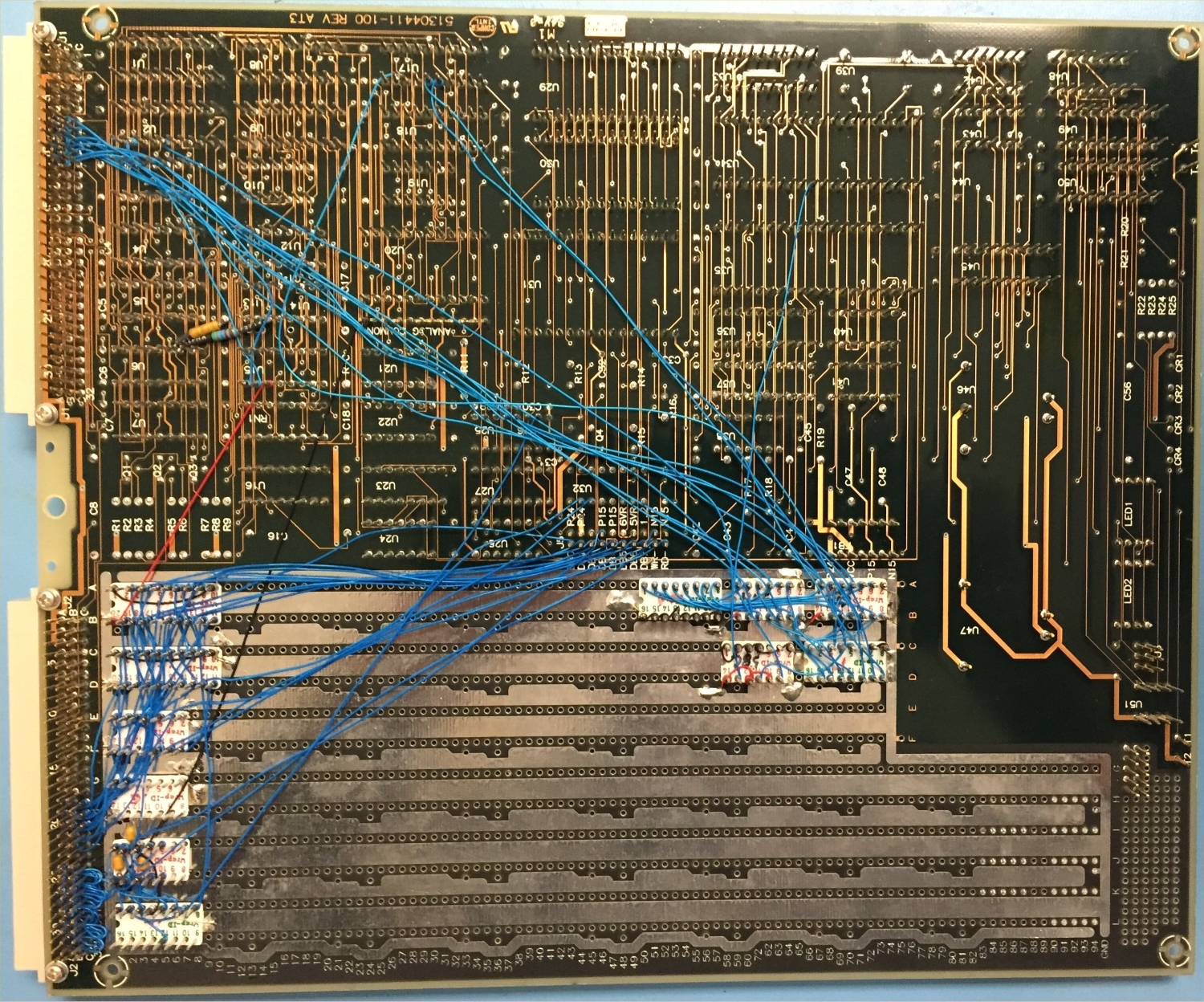
From 1988, the test controller with "copper artwork section" (bottom side view)
This 1988 design served us well, and we still have fixtures today using these test controllers. One of the benefits of this setup is that we’re immune to all the changes in PCs over the years, including the introduction of Windows. We continued to use our DOS software until around 2012, when a Windows version was finally introduced.
In 1996, a new product was introduced, so we took the opportunity to make a new test controller design. We switched to an 80C251 processor (16-bit), and other features included an analog section that was self-calibrating, and the introduction of a pair of CPLDs. These CPLDs were used for some of the common logic, but were mainly intended for use in building the point logic with software, rather than a mass of wire-wrapping.

From 1996, the test controller with CPLDs to further reduce wire wrapping (top side view)
Technology marched on, and in 2004 we were once again looking at a new product to test, and so went after a new test controller as well. The 82C251 never caught on, and there were better 8051 variants available. We went with a P89C51RD2, which had SRAM, FLASH and EEPROM on board. Running at 24MHZ and six clock cycle instructions instead of the original 12, we also saw some decent speed improvements. The RS-485 links were bumped to 750K to support faster speeds that the newer product was using. It was getting difficult to find through-hole logic, so some of the common area were now surface mount. We continued to use socketed parts for the buffered signals going to and from the product being tested, which allowed for easy repair at the factory. If damage occurred to the SMT common electronics, field repair was difficult to do, and the test controller was typically sent back to our facility for repair.
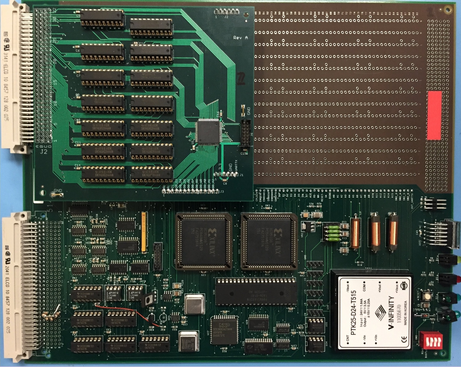
From 2004, the test controller with many advancement including more SMD parts (top side view)
From 2004 the test controller with even fewer wire wrap connections (bottom side view)
In 2012 I started using PCB-based daughter boards for the point logic. This reduced the wire-wrapping to very little, if any.
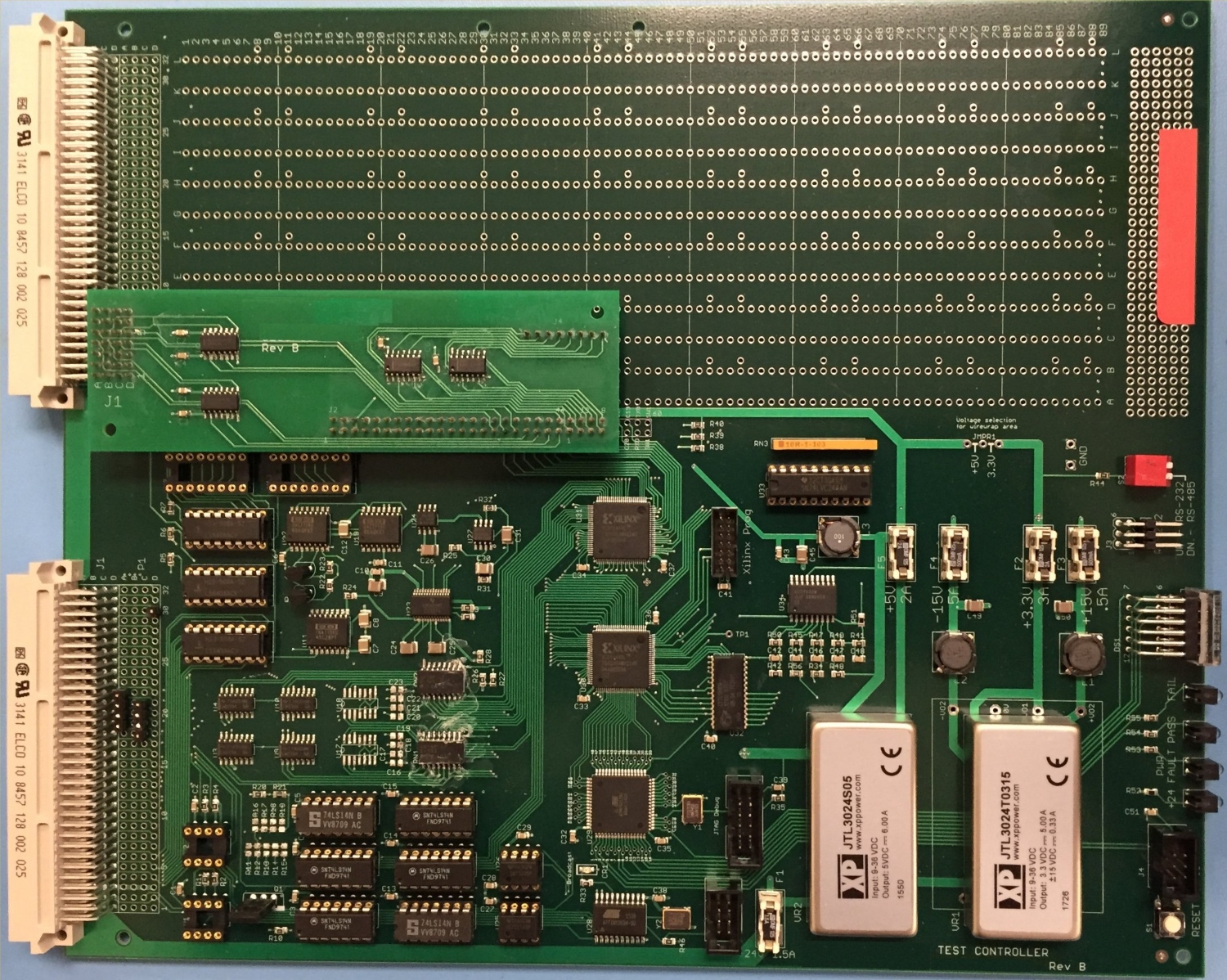
From 2012, the test controller with daughter boards (top side view)
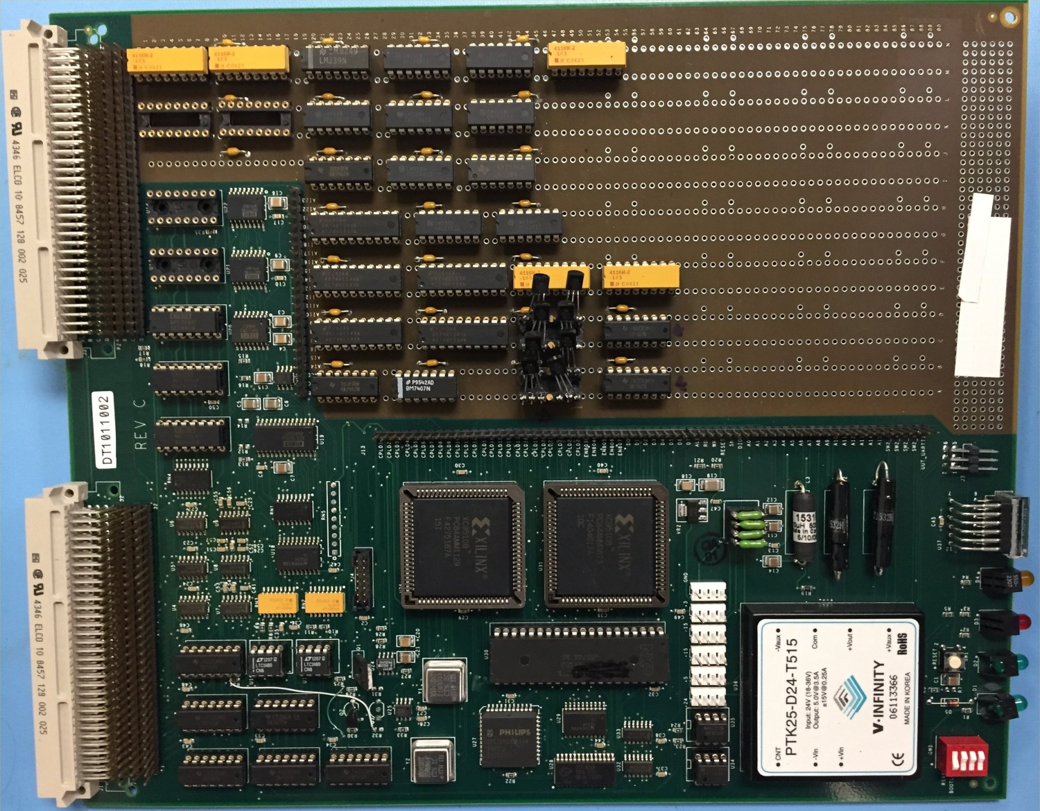
My most recent design was driven by parts obsolescence. The 8051 variants were disappearing, as well as supported development tools. The CPLDs were end of life (EOL), so it was time for a new design. I selected the Atmel ATMega1281 and the Xilinx XC95144XL, one of the few remaining CPLDs that was 5-volt tolerant. Except for buffered outputs, all of the common electronics are surface mount. A second processor (ATTiny1634) is used for communication, either the 375/750K RS-485 or other protocols. The layout is designed to support daughter board add-ons, but you can still use the wire-wrap area, with selectable 3.3V or 5V power.
From 2016, the test controller with nearly 100 percent SMD parts and no wire wrap connections (top side view)
The Future
What do I see for the future? Our electronics world is governed by supply and demand – these days that means smartphones. Most of our IC vendors are dropping 5-volt and 3.3-volt parts in favor of 1.8 or lower voltages. Large capacitors and other parts are becoming less common as well. Our next generation test controller will probably move to an ARM-based processor, and the CPLDs will be replaced with FPGAs.
Kelly Small is a principle test engineer with a Honeywell division in Phoenix, AZ. He’s been employed there for over 40 years, with 38 years in test engineering. Kelly has also been a participant in SparkFun's Autonomous Vehicle Competition, and his high-tech treasure chest was featured on our blog.
We greatly value not only Kelly's participation in our events, but also his involvement in the open source community. Please feel free to ask any questions below in the comments section, and thanks for reading!


I couldn't help but notice the "From 1986..." board photo has parts with '87 and '88 date codes.
The board was designed starting in 1985. We probably built at least 10 of these full wire-wrap versions before going to copper, so some of them were built later. And over the decades, things break or burn up, and need to be replaced. I'm actually debugging with that exact controller now, and I'm afraid to touch it or move it around.
Thanks for the nice "walk down memory lane", Kelly!
Much of my career was also in test engineering. I was mostly involved in testing at the IC level. I have a few things you're probably aware of, Kelly (and Pete), but some readers might not be aware of and will at least find interesting.
First, you mention that your boards involve a lot of wire wrapping. There were (and probably still are, though I haven't needed it this millennium) "NC" (Numerically Controlled) machines that automatically do the wire wrap connections. Also going into this discussion is that CAD (Computer Aded Design) systems for PCB (Printed Circuit Board) design, until the last couple of decades, have required much more computer power than could be provided by the typical PC of the day, so it was often not practical to do a custom PCB design when you only needed a few copies. (Today there are open-source PCB design packages that output the industry standard "Gerber files", and lots of vendors that will turn those files into physical PCBs at reasonable cost in a relatively short time.)
My next point is that the goals of PCB-level testing are somewhat different from the goals of IC testing. For PCBs, the goal is to verify (either directly or indirectly) that the UUT has no shorts or opens, that all of the correct parts are installed corectly, and that they are all functional. For IC testing, our ideal goal is to verify that for each UUT, or as we refer to it, DUT (Device Under Test) every single transistor on the device is good, that it will function over the entire range of speeds and voltages that the spec sheet says, and that it lives up to the specified output drive, input load, and power consumption specs. The testers are also used to do a whole bunch of "characterization" testing, used to establish things like temperature ranges, and all of those bizzare charts at the end of the typical data sheet. (High reliability parts, often referred to as "MIL-SPEC" parts, are given much more extensive testing on a per-DUT basis than are "commercial" or "automotive" grade parts.)
IC testing has traditionally fallen into 3 separate catagories: logic (or "random logic"), memory, and analog (sometimes referred to as "linear"). One of the sayings is that "you use logic to test memory and memory to test logic". Logic testers (where I spent most of my time) have huge arrays of memory that store "stimulus/response" test vectors which will be presented to the DUT sequentially (usually at, or just above, the DUT's guaranteed maximum speed), to verify its functionality. Memory testers (I was involved in designing the architecture for the memory test "options" for multimillion-dollar IC testers) use logic to put patterns into RAM and verify that they can correctly store them. (Pattern sensitivity is the big bug-a-boo in the memory world, especially for DRAMs.). Analog testing often times involves external instruments (lovingly referred to as "rack and stack"), though things like "arbitrary waveform generators" and high-speed high-precision DACs are common.
One last item for this comment: Board-level testers (especially "bed of nails" testers) often have much lower speed capabilities than do the IC (or "chip") testers, partly due to the differing goals mentioned above.
Yes there are many times I must remind management that our functional testers are to verify the board was built correctly, not verify the design. Although there is certainly an overlap. I worked on the Teradyne systems when I was doing ICT and some functional on an L210. Later we started using the Z1860 (Zhentel, then Teradyne) for ICT. I know a few guys that work for MicroChip down the road and they do the IC test developments that you describe.
Still have this horrible thing: https://photos.app.goo.gl/8qXrdaXFajVaFRSAA. I made a 4K static memory board for my ZX-81 with it. It worked for a year or then started glitching out. Typical of the technology.
Nothing wrong with wire-wrapping, if you do it correctly., i.e. square posts, not round. I have my trusty wire-wrap pencil I bought back in the 80's, probably from Radio Shack. I see SparkFun still sells the exact same tool, except it's blue. This article referenced the treasure chest I did 9 years ago in the bio. There are several pictures there that show the wire-wrapping that was used as well.