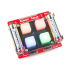
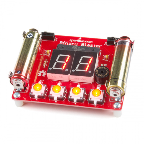
One of my favorite SparkFun products is the Binary Blaster. It’s a lovely little soldering kit, which, when completed, is a fun game to help the user practice converting from decimal and hex to binary! I picked one up and had fun putting it together and playing it, but found that rather quickly I mastered both game modes and wanted more of a challenge!
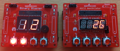
Introducing the ASCII Annihilator (Asc Blaster for short)! Based on the board for the Binary Blaster, this mod adds an additional game mode, a 4 character alphanumeric display, and can quiz you on a large swath of binary, hexadecimal, and even ASCII! You can even mix and match game modes and difficulties by holding different combinations of buttons on boot.
The only new part required for the mod is the alphanumeric display itself and a few bits of wire to use as jumpers! Performing the mod requires modifying the PCB by cutting and modifying traces and bending the display pins. If you feel up to the task, you can buy a binary blaster, whatever color display you want, head on over to the github page, and follow the instructions! First though, lemme sit ya down and walk ya through the design!
The binary blaster only has 4 lit buttons on it, just enough to input a binary ‘nibble’. That only allows you to be quizzed up to 15 in decimal or F in hex (0b1111). The display, however, consists of two 7-segment characters, enough to display up to 99 in decimal or FF in hex! I realized that with an extra switch, one could toggle the lit buttons between two nibbles, enough for a full byte! I quickly implemented this and sacrificed the original sound switch and buzzer for this ‘nibble switch’. (In the future I might release the code for this version, but I managed to lose it so it’ll have to be rewritten)
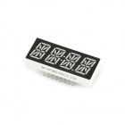
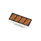
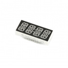
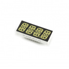
The stock blaster can only quiz up to 15, but with a nibble switch, it can go up to 99!This was fun for a while longer, but after some time I started to be annoyed that while I could input up to 255 on the buttons, the display could still only show up to 99 in decimal. Plus, a full byte can be used for more than just numbers! ASCII, simple color values, and even assembly instructions for some architectures can be stored in a byte! As it happened, SparkFun had just started selling a 4-character, 14-segment alphanumeric display, and as soon as I saw it, I knew the final form of my modified Binary Blaster: I would add one of those displays and quiz the user on all of ASCII! I bought one, freed it from its Qwiic-based driver board, and immediately set to work incorporating it.
My first hurdle was a lack of pins. With one pin for the nibble switch, one pin for sensing each button, another for driving each button’s led, and up to 17 for the display, that makes 26 pins. That's bit of a problem with the keyed ATMEGA328 only having 21 pins available. There are a few ways to get around this, the easiest of which would be to keep the Qwiic driver board on the display and talk to it over I2C. That approach, however, seemed complicated and boring. The method I settled on was even more complicated, but much less boring: charlieplexing!
Charlieplexing is a really cool method of multiplexing that takes advantage of two facts:
Diodes will only allow current to flow one way.
When you set a pin on a microcontroller as an input, it puts that pin in a “high-impedance state”. That is to say it effectively disconnects that pin from the circuit.
Using this knowledge and some fancy routing, one can achieve surprisingly high multiplexing efficiency with just a bunch of diodes. Now, most of the time this isn’t too useful, since it’s much easier and cheaper to just buy a chip that does the muxing for you than to buy a diode for each of your outputs. However in this case the display and lit buttons all use LEDs anyway, so we get those diodes for free!
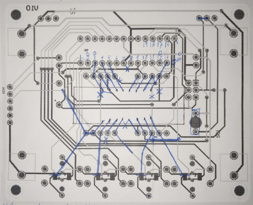
The next step was layout; I wanted to keep the hardware modifications as simple as possible. This meant minimizing the number and length of jumpers to make it compact and easy to do. This part was really fun! I printed off some images of the PCB layout and doodled on them with a pen until I’d figured out the best way to modify the board.
With the hardware modifications all done, it was time to move on to programming! I could have modified the Binary Blaster code (that’s what open source is for, of course!), but I really wanted to release the code under GPLV3+, which the Blaster’s CC-BY-SA license is incompatible with. This meant a total rewrite, but I certainly took some inspiration from the Blaster code. Particularly, the original Binary Blaster’s display implementation was wonderful, assigning all of the display pins to sequential pins in the microcontroller’s registers. This allows one to easily set a given display state simply by writing a byte directly to the registers all at once. My code is by necessity a bit less elegant, as I had to do some funky hardware routing. I still tried to adapt the approach Pete took to my design and wrote a helper function that addresses the display as a pair of bytes, each bit of which represents a segment of the display.
If I was addressing the display the more common way, with each pin on the microcontroller going to one pin of the display, I could have used any of the many wonderful libraries people have written to use displays like this, but since I charlieplexed the display into the buttons, I had to write it from scratch. Writing this function was definitely the hardest part of the project, as it requires converting the given bytes into a sequence of pin states, with specific pins high, low, or high-Z, which the micro then steps through one at a time to give the illusion that the whole display is lit in the desired configuration at once.
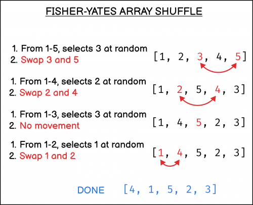
After a lot of other work implementing basic helper functions and the skeleton of the code, I got to my next interesting challenge: shuffling the questions! This is mostly notable because I like the algorithm I found to do it: the Knuth/Fisher-Yates shuffle algorithm. The nice thing about this algorithm is that it shuffles the questions in place and as one goes, so there’s no lengthy shuffling process at the beginning, and it keeps track of which questions have already been asked. All one needs for a Fisher-Yates shuffle is an array containing all the questions, and an index keeping track of where one is in the array. It goes like this:
The Fisher-Yates algorithm runs in 0(N) time complexity. Image: sebhastian.com
Using this algorithm, one not only shuffles the questions quickly and with a little extra memory, but one shuffles the questions as they go. This ended up being a lifesaver later in the project when I found that the randomness available at the beginning of the game was almost nonexistent.
That brings us to the next hurdle: randomness. The most common way to seed the RNG of a project like this is either from variations in timings and durations of user input, or by polling a floating pin’s analog value. On boot, the only option available is to poll a floating pin, but unfortunately this proved to be insufficient on its own. My solution was to poll the floating pins in a loop until they changed, and then use the time that they changed to seed the RNG. This gets us most of the way there, but just to make sure the shuffle is random, I reseed the RNG after each question with the time in microseconds that the last question was answered. Since this harvests randomness directly from the user, it’s plenty random enough for our purposes, especially since the shuffling algorithm picks a random question every time instead of just shuffling the questions at the beginning.
With the hardware and the software done, the only thing left to do was play it -- and it was excellent! The end product is fun to play with, and has varying levels of difficulty to keep gameplay fresh! The only other thing I added was a little card that flips up from the back of the game with an ASCII cheat sheet on one side and a dec-to-hex cheat sheet on the other.
One final note: apart from actually soldering the thing together, all the designing and programming for this project was performed on the hour-long bus commutes to and from work while balancing my laptop, the annihilator, and a multimeter on my lap. The development took around 2ish weeks, over which I attracted quite a few curious or concerned glances from fellow bus patrons! A discussion over lunch with Pete Lewis, the designer of the original Binary Blaster, revealed that development on public transportation is a common theme with this project, with the original Binary Blaster having been largely coded on a flight to his honeymoon!
Additionally, I took a timelapse of the construction of an ascii annihilator, head on over to twitter to check it out:
Want to see a SparkFun modification project? Funion Juno made some changes to our Binary Blaster to increase functionality and expand gameplay! #sparkfun #electronics pic.twitter.com/grKcs4nA52
— SparkFun Electronics (@sparkfun) November 2, 2022
The Binary Blaster Kit, including the Binary Blaster PCB, programmed ATMEGA328, and PTH Buzzer along with some other materials, is available and ready to be tinkered with!
Have you made any modifications to SparkFun products for extra capability? We'd love to see! Shoot us a tweet @sparkfun, or let us know on Instagram, Facebook or LinkedIn.
