This week is a special one. Not only is Maker Faire Bay Area this weekend, but we had our first demo for the product video that could probably kill someone. We've made a treadmill with a mind of its own, a game of Jenga that plays YOU, and an off-road vehicle with an attitude. But this week, we decided to use some of the new spark gap igniters for an idea I had and it just turned into something scary. Check out the video below.
Vimeo version found here.
I wish everyone could just experience what this thing was like in person. My ears were ringing the whole evening when we were first testing it. It's loud. Loud enough that you can hear it pretty much anywhere upstairs in our building when it's on. And not only that, but the sparks are erratic and after it's been on for a little bit, the whole room smells like ozone and burning plastic. It's, well, just wonderful.
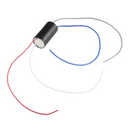
You asked for it, and here it is. This spark gap igniter is very similar to the one used in the SCORPION. Feed it 5 volts and it spews out bolts of electricity. We didn't get a datasheet, so I can only speculate how it actually works. My guess is something to do with the fusion of unicorn tears and Leprechaun blood, but I'm not an engineer. I can say that it can easily spark across a 0.5" gap and will ignite combustible gasses just fine. You have to love a product when it's primary objective is explosive detonation.
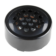
And now for something less painful. This little speaker is designed to be mounted to a PCB. With 0.1" spacing, it also works well in a breadboard. It's just small enough to fit into that embedded board your designing. Speakers can be problematic because there's not a great way to mount them. With this one, just mount it directly to your board and you're good to go. It's not terribly loud, but perfectly adequate as a buzzer, warning system, etc.

Sugru now comes in 8 packs instead of 12! You don't have to buy as much and there's less of a risk of expiration with smaller packages. It comes with 2 packs each of red, blue and yellow, and one each of black and white. It has a lot of uses and should be in your tool box if you build a lot of stuff (or break a lot, either way).
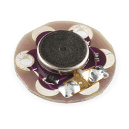
And lastly we have a new version of the LilyPad Vibe Board. This one uses an SMD vibe motor which is much easier to solder, making it much easier to produce. Use it as a (nearly) silent alert system, feedback mechanism, or, well, you have an imagination.
That's all we have for this week. Have fun at Maker Faire if you're going. Be sure to check back next week as we're already planning a demo and are getting some other stuff ready for the site. Thanks for reading and see you next week.


You know, I think the fact that the 7-segment display pulls 20 amps and is 105dB loud makes it the coolest thing I've seen yet.
Wow! I can't believe, in this group, no one has commented on the misspelling of SCOPRION. I think this is progress!
You beat me to it! I figure SCOPRION is one of the products of SprakFun.
it's Friday night, I'll fix it next week. Think you can handle it until then? ;-)
Handle it? I will roll around in it like a bathtub full of hundred dollar bills.
You should make a point system for people who point out website mistakes (EG: Spelling, missing links, etc). After a certain number of points, the person would get a Sparkfun giftcard as a prize.
Only if we get to visit your job and point out your mistakes and get a prize from you. It's only fair :-)
I see a Taser in my future! (And a Jacob's Ladder, and a Tesla coil, and a...) Judging by how the frequency seems to go up with shorter spark distance, my guess is it uses a simple Hartley oscillator to drive the coil. That also leads me to wonder how critical that 5 volts is. Could I run it off a 6v battery pack, for example? For your seven segment display, how about using Xenon flash tubes as the segment bars? That should "contain" the sparks quite nicely, plus give an epic plasma display!
we didn't test this out THAT much, but I will say we burned one up at 12v... so, don't go TOO high, but 6V should be just fine.
TWELVE volts? Eep! Did it produce quite the spectacular display before emitting it's high-pitched swan-song? Or just die without fire and fanfare?
it was pretty boring. it worked and then it didn't. that was about it :-)
the gap was slightly bigger, but that's about it.
Oh boo :( It's annoying when something goes wrong, but doubly so when it goes wrong in a really boring and mundane fashion :(
How about running each segment through one of those 1" glass fuzes (pre-blown of course)?
Re: Sugru -- Cures, not dries. ;-)
I got a couple of speakers identical to that from the junk bin from a former job. Wish I still had access to that! Use it in my optical Theremin (photoresistor in the feedback loop of a relaxation oscillator). Fits in a solderless breadboard with a little force.
You could try using those small xenon tubes (i have a bag full of these tubes) from disposable cameras, they still look sparkey, less noisy, and only need about 2kv to fire directly without using trigger electrodes, the current draw will limit it down to 2kv anyway. Since the voltage will be much reduced it should be much simpler to manage channel separation.
good idea. but we don't sell those :-)
You should sell those :D Plus the U shaped ones and the trigger transformers :)
I can check into it. I was looking around for some because I'm thinking of making some remote RF camera flashes for cheap. Maybe I'll dig around and see what I can find.
Yes! Please sell a replacement for my Cactus triggers. I would much rather give money to SparkFun than Ebay.
I have the Yongnuo 603 triggers and I think they use something like these
The sell whole assemblies with small flashes at allelectronics.com as well as the u-shaped flashes by themselves.
edit: And they're really cheap.
I see a Remote potato gun igniter in my future!
I have an idea about how to get it working! Unfortunately, I don't have enough time to type it all out now, drop me an email and I'll try to explain it with crummy drawings and a smattering of words :)
post it here so we can create a discussion!
Are the outputs on the spark gap igniters isolated from the inputs, or are the in/out grounds electrically connected to one another? If they share a common ground, it might be worth it to try separate isolated 5V supplies for the different segments.
Why not have only one on at a time and switch between each one?
we thought of that, but each one takes at least 50ms to start up, and there needs to be a delay before the next one can go on (or else they spark to eachother), so what you saw in the demo above was about as fast as we could switch them.
So you couldn't just asynchronously pulse them so that they all appeared to be on by PWM?? (Guess that would be too easy ;-P)
yeah, that didn't work. some of what you see in the video is exactly what you suggested... if you put one segment on for a second, gave it like 200ms to turn off, then went to another segment, that was the only way it could work. any faster and it would just be a mess. we needed much better insulation.
Can you tell us what the polarity of the segments are? If you put like polarity segment ends next to each other they will be less likly to arc between them. There are six points that you would line up. Top left would be -, top right would be +, middle left would be +, middle right would be -, bottom left would be -, and bottom right would be +.
Yea... instead of plastic use glass or ceramics... I was working at the university with some insulations in laboratory... There is no perfect insulation ... when spark makes own way through material is too late...
Sugru can come off of certain things very easily with soapy water. I tried it on my camera to attach a lens cover. Fell right off!
no kidding? I've always found that once it sets, it's there for good. how long did you let it cure for?
Robert, some of the banner's links are dead.
bummer. which ones specifically? I can refresh and try each one, but if you tell me which didn't, I can fix them.
IOIO 2nd down. There might be others tho
Old Macdonald had dyslexia IOIO E
He fixed it already...
How many milliamps is this spark probably? It seems like it would be below the 10mA danger zone for a healthy meat popsicle, but I'm no expert. If this draws 15 watts off 5 volts at peak (3 Amp draw) even if the voltage of the spark end were as low as 5000 volts (which I doubt it's that low gauging by the spark gap width)that would still be less than 10 mA right? I don't know though because I don't know if the oscillator that drives this make it more complicated than I realize. Perhaps it gets turned on and off really fast and that would change how much juice it delivered? I'm just trying to gauge the danger level here. Obviously it would still hurt... a lot. Am I missing something here?
Please tell me you did not spend 15,000$ for that tiny booth at Maker Fair? Where do they get off charging that kind of money? It ends up hurting the consumer. Surprised how few vendors were actually selling anything, more of a meet and greet!
I'm trying build a pill dispenser and I'm new to arduino. So I was wondering what arduino would be good to control a small motor and run on a daily timer? Or if arduino is even my best microcontroller option.
Welcome to Arduino! I think that an Arduino Uno and an Ardumoto controlling a small motor for dispensing is your best bet, or even a small solenoid.
The next 0.1" statement in the text should (maybe?) be 1.0", says the datasheet although the text is kinda ambiguous. "And now for something less painful. This little speaker is designed to be mounted to a PCB. With 0.1" spacing, it also works well in a breadboard."
What exactly is the problem.
The leads have .1" spacing that fit on a board also with.1" spacing.
I think that if you use some glass fuses it could work http://www.sparkfun.com/products/10166 , i know that it will burn the first time you turn in on but then it will travel thru the in side of the glass and of couser you will have to isolet the end of the fuses with a hot glue gun or some shirnking tubes. That's what I would do
Awesome! Very dangerous, yet somehow eerily inviting... What kind of power supply is that?
For the 7-segment, you just need a bit more ionization. Perhaps slots through with an "ion breeze" type blower blowing through it from the back (blowing through the vents always helps, right?). Or, for a solution with fewer moving parts, a David Hahn style solution should work pretty well, just like in a smoke detector. Even if you still have to run them one at a time, you should get fast enough response to use POV to complete the display.
Might not be quite so safe as this version though, depending on how you do it.
Could the sugru make more effective channels? What's its bulk impedance?
Robert! if it is hurting your ears then you should be using PPE for your ears! Dude, once you lose your hearing you don't get it back! Trust me; My Dad barely hears anything because of the noise he's been exposed to over the years.
Sparkfun needs a safety officer!
Also keep your spark coil away from anything vapor that is flammable.
WHAT?! SPEAK UP!
It takes about 30K volts to create a 1 cm spark. So, the spark gap igniter does put out a high voltage!
I have read anything from 20kV to 70 kV per inch. It all depends on the air conditions, humidity, and even the shape of the two electrodes.
Pacman Shaped?
What? No Jacob's Ladder?
Dude just stop. Nobody thinks you are funny.
Spellcheck: ...into that embedded board your designing... (4th paragraph)
You guys do realize that you're in the nose-bleed section of the planet up there, so us normal people at lower altitudes will see something different.
http://en.wikipedia.org/wiki/Gas_discharge http://en.wikipedia.org/wiki/Spark_gap
Also, 8 segments@20amps means ~2.5A into each unit. 2.5A at 5V = 12.5W. At a few thousand volts at 12 Watts... So, just a word to the wise, you could hurt yourself quite badly with this thing. Be careful :(
It seems like it should work if you use a material that has a higher resistivity than air (such as PET plastic) and don't allow air gaps between the layers.
So, you probably can't make it out of multiple laser cut sheets, as there are small air gaps between them. But it would be easy to make on a manual mill. Just have to make sure that the shortest path is between the two electrodes. (AKA, that it can't jump over the barriers.) Also, make sure that the equivalent resistance of the material at a certain thickness is greater than the resistance of the air gap.
Oh, for reference, air has a resistivity of about 1.3×10^16 to 3.3×10^16, ABS is probably about 1×10^13, and PET is about 10×10^20. (So, your ABS is actually a better conductor than the air, which is why it doesn't work.)
You can figure out the resistance by R = pl/A (Where p is the resistivity, l is the length, and A is the cross sectional area.)
we may try gaskets between the layers. we have a mill, but I don't know how much time I want to spend with this :-)
Also, I might be willing to make one for you guys. It should be super simple. But, it wouldn't happen until the beginning of next month. Let me know if you are interested.
You will still have to change your material. ABS will never work.
Ah, well with jonboy12's arrangement it might, actually. Try that first, and then let me know.
ON the "Spark Gap Igniter", I've used something similar to drive HeNe laser tubes, 5VDC in and about 1.5Kv out at about 1 - 5 mA. They tickle a little if you grab the wrong leads, ;-P
SUGGESTION and Question Pardon the new guy but couldn’t you turn them one at a time instead of all at once. And count on persistence of vision it fool you in to thinking they are all on? Could you use it to make a plasma speaker?
yep, tried that. see my comment above. they don't turn on and off fast enough to make it look like a solid display.
o sorry ... couldn't you make use two of them on each segment. so that each segment is divided in to two pieces with the positive ends in the center and negative are on the outside so the path of least persistence is ware you want it to go.
sorry to bug you ..
no problem at all.
didn't think of that. but that does double the complexity and parts... we may just need different materials for better insulation.
one more thing before i leave you in piece. There is a way you can arrange it so whenever the ends are close they are the same polarity . I have a asscii drawing but it got mangled . assuming it is dc .
much better. you did forget that the middle section has a junction of 3 electrodes, but yeah. we may try that.
Wish I would have ordered the Sugru when it was $2 more and you got half-again as much. (But at least it's back in stock.)
Since the spark gap igniter is so loud, I wonder if it could be used as a speaker. I am thinking something similar to Masters of Lightning Play Ghostbusters.
There is a band (forget the name) that shows up at Maker Faire every year (and other places) and does the Tesla coil speaker thing. It gets old really, really fast. Every single thing they play sounds like the world's largest swarm of angry bees. It's a neat hack, but IMHO totally not worth doing. I love music, but I'll put my effort into instruments that are actually pleasant to listen to. If it only took 10 minutes to hack together, I might try using one of these coils to make the Devil's Own Kazoo, but I would expect it would hold my interest just about as long as a kazoo. There just isn't enough variation in tone quality, and the tone is pretty harsh.
Arc Attack
we thought about that. we didn't have time to build something and then further tweak it. with stuff like that, there are too many variable to go quickly with a build. and at the end you aren't left with much to show for all your time if it doesn't work.
we may revisit this one and see what else we can do.
If you take that gripper from the other week that takes the medium servo, attach one lead to each side, you could then vary the distance of the arc to make a variable sound device. Closer distance, higher pitch, greater distance lower pitch. Some calculations and an Arduino, and you have a spark gap instrument.
Or hook up a bunch of buttons, and a spark gap piano !
How about a bank or 8 grippers and spark gaps, and buttons, a real piano !
It is interesting to know how little time you guys normally have to put together both the new product videos and demos. In most cases, the result certainly doesn't look like everything was designed, built and filmed within three days.
Also despite not being able to totally achieve your project goals, at least you were able to identify the main reasons why spark gap displays never hit the mainstream (high current, very loud noise, EMI issues, etc...).;)
About EMI... long time ago i had a board with a PIC that did reset every time it tried to power a nearby relay because the load caused a small spark in the relay contacts. I'm impressed that 5V*20A=100W of sparks are not causing the Arduino to reset :O Epic test by the way.
yep. something like the scorpion was built in 2 days, filmed in about an hour on thursday afternoon and posted the next morning on Friday. This is how it goes pretty much every week. Both Nick and myself have a lot of other responsibilities and I can only personally devote a few hours to these videos each week.
It's worthwhile because it gets me to your site on a weekly basis.
It is one of the more interesting parts of my job :-)
I noticed the Imax lipo charger in the video. Robert, can you tell me if it is made by the genuine Imax brand or some copycat brand? (Genuine brand ones have a shiny sticker on the bottom)
It has a shiny QC passed sticker, and that's it. I took a pic if you want, but it's nothing too interesting. Not sure if they are genuine or not, but we've used it a lot and it's been good to us.
If you get around to taking the pics Email me. My email is in my profile I think.
Its likely a copy then.
Could I ask if you could take a few high quality pics of the component IS's used on the inside? I have been debating whether to order one or not for a few months now. The only thing holding me back now is components used and the quality of the pcb & solder job.
I'll see what I can do. Soldering job is quite good, nearly excelling inside actually. most ICs are covered by the LCD screen. I can see what I can come up with, but my camera is at home and all of our good stuff is at Maker Faire...
Well as long as i can read the ID's in the pics, it will be fine.
well, I don't own an xray camera, and it's mostly underneath the screen, so it's a no-go. you wouldn't be able to see anything other than a few caps and surface mount resistors. all the good stuff is under the screen and I'm not gonna take mine apart :-) we use it and it works well for us.
Actually can you at least tell me whether the uC is a PIC or Atmel? And if you could, tell me the package of it?
seriously, it's covered by the LCD. completely... without completely desoldering it, there's not way to even see what's underneath... at ALL.
Sorry... :(
I was asking what the uC was because I wanted to reflash it. I only have a AVR flashing tool so its kinda important, also I thought it looked kinda like this so you could just peek underneath...
nah, it's fine. it's just inaccessible. but I will say it works fine. I wouldn't get too hung up on if it's 'real' or not. the design seems simple enough and it's built well. it you need a charger, it will do that and be reliable.
k
You could probably use that spark igniter to drive a home brew Tesla coil. In fact I may order one and try that. Do you need to pulse the input or does the device run off pure 5v DC? Once thing for sure, this product is your namesake (SPARK FUN ... get it?).
so, in the last shot, where we had just a single one hooked up, it's going directly to a bench power supply. I thought it was in the shot, but it was just off screen.
you can use a 6V SLA, or any 5V DC source.
Seems like you could almost weld small things with this sparker... solder tabs on batteries?
doesn't seem like it. the paper cover we were using didn't even get remotely burned. we actually used some thermal paper in a test and it took a few minutes to make any mark on it.
try it out though!
That's a good point. I may have to try this!