Enginursday: A Template for Edison Blocks
Our design philosophy behind the Edison blocks, and how you can help evolve the ecosystem!

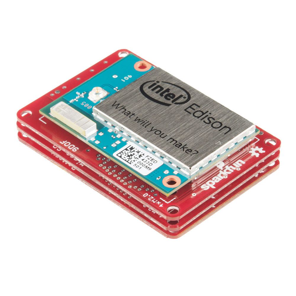
It's been a whirlwind few days for us here at SparkFun. On Tuesday Intel(R) announced the Edison, a tiny development platform that packs a wallop of a punch.

Here's the rundown if you missed it: hidden under that RF shield is an Atom processor -- a dual-core, 500MHz x86 CPU -- supported by 1GB of LPDDR3 RAM, 4GB of flash, and, most important of all, integrated WiFi and Bluetooth (2.1 and 4.0/BLE). It comes pre-installed with a Yocto Linux distribution to help manage all of that hardware.
To interface with the Edison you have to connect something to its fine-pitch, 70-pin, Hirose connector. On that connector, the Edison breaks out I2C, SPI, multiple UARTs, and all sorts of GPIOs, so there should be no shortage of components to connect to it.
To get every one started, Intel's released a couple of base boards: the Arduino Breakout and the Mini Breakout. Those should help ease folks into the new platform; they're a great foundation to start toying around with the Edison and exploring its capabilities. Moving beyond that, though, we hope our assortment of "blocks" will help to boost the Edison ecosystem and give the powerful little module the hardware support it deserves.
In the short time we've had to play with the Edison, we've brainstormed a few of the more common components we think it will be interfaced with. That list includes anything from simple console boards to 9DOF IMU's, servo drivers, DC motor drivers and OLED displays. We've segmented those sub-circuits into 14 unique boards we call "Edison Blocks", all designed to stack together so you can pick-and-choose which components you want to integrate into your Edison project.
Combine the Edison with a 9DOF, motor controller, and console block to create your own balancing robot!
The Edison Block Standard
With over a dozen boards to design, our engineers had to begin by coming up with a standardized layout so they'd all work together. We began by painstakingly laying out a general purpose escape route -- a set of traces and vias that would break all of the signals out, while also passing them from the bottom connector to the top. Then we built in rules like where inputs and outputs should go, or where the board should generally be void of connectors. We ended up with a template that looked a little something like this:
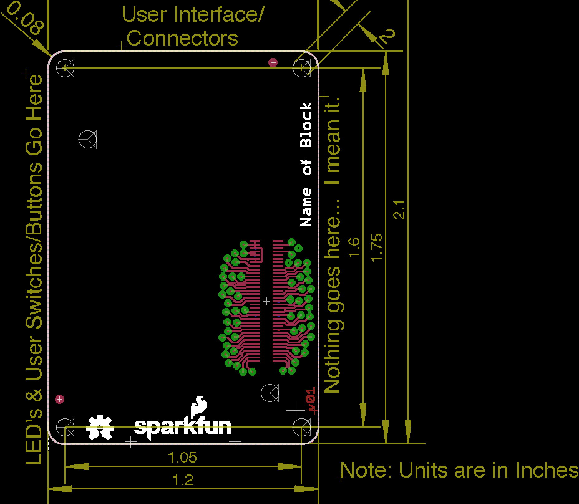
The thought is: if we all follow the same standard while designing these boards, they should be interchangeable. Plus, any enclosures that might come down the pipeline would be agnostic to the Edison blocks you're sticking in there.
So far we've designed about a dozen boards according to this spec, but we want to see much more than that. We want Edison blocks to take off, maybe they'll become the next evolution of Arduino shields. But to get there we'll need the help of our friends and community. So here are our template design files, take them and see what you can come up with!
On top of that Intel's documentation might be of help, particularly the hardware guide.
We're super-excited about the Edison ecosystem that we're helping to cultivate. We think it has tons of potential, but we'd love help getting its feet off the ground. If you have an idea -- something you'd like to see integrated with the Edison -- use our template and try designing an Edison block for it. Want to add GPS or XBee capability to the Edison? Design it! Then let us know what you've come up with!


I appreciate the thought and all, but there are two good options for open-source ECAD tools suites: gEDA and Kicad. It really is irksome (and may I add hypocritical?) that you release your design files only for a free-as-in-beer cripple-ware CAD system.
While I agree that it would be nice if KiCad et al were more prominently used, I do wonder why you're saying it is hypocritical for SparkFun to post Eagle CAD files. While SparkFun certainly promotes the open source ideal in many ways (from posting boards to begin with through open sourcing some of their server back-end), that shouldn't be interpreted as SFE saying they're the frontrunner of all things open source. As such, I'm fine with them using whatever product serves them best, and if that's currently Eagle CAD, so be it; I can't blame them (that's neither here nor now), and certainly don't consider it hypocritical.
As an aside - it looks like the board file opens fine in KiCad (dimension texts are off), not sure about the schematic (be that through the ULP or Upverter), so that's a good place to start if anybody wanted to make KiCad (and/or gEDA) versions.
I know I'm late to the party, but I keep finding this page every time I look for more information on the Edison/Hirose connector and it looks like some others have taken the time to build a Kicad layout for the connector, which is really the key part of this Sparkfun design file, IMO. Here's a link to the github project...
Intel Edison Template
This is just one example of how SparkFun is electro-awesome. Ordered Edison stuff from you to play with right after it was announced and waiting eagerly for it to arrive!
One bit of info I can't seem to find in the docs anywhere (though I might have just overlooked it in the excitement) -- is there a part number for the exact 70-pin Hirose connector we need to use? Or alternatively, will SparkFun be adding those to stock for us to use in our own Block designs?
Yeah OK, "Hardware Guide" right at the end there. Got it. Question still stands whether SparkFun will carry them, though. (Also, the "Block" standard is the 2.0mm mating height?)
We're planning on 3.0mm; that gives enough clearance for micro USB and other slightly higher profile parts.
we can surely sell them. they are pretty tricky to solder on their own though. it can certainly be done, but don't expect to get it right the first time on your first one, unless you're really comfortable with smaller pitch SMD.
Thus https://www.sparkfun.com/tutorials/59
Yeah, it's pretty hard to solder at that pitch. You have to be careful to not put a lot of pressure/force from the soldering iron on the connector or pads. Pads that thin are a lot easier to break. Experience is a must to solder this baby.
exactly :-) but it still takes practice to get it right.
What we really need board-wise is a master breakout that breaks out every pin on the connector, even no connect ones. I imagine someone could use those unused pins to send data/power around in the stack between custom boards.
Do you carry/plan to carry spacers and screws to give some mechanical rigidity to the stack?
yes. still looking for them, and what combinations make sense.
The note says "Units are in inches". The mounting hole size is listed as 2, but I'm assuming it's 2mm. Am I correct?
yeah, it's 2mm.
so... this thing is as, or more, powerful than my old 486/Pentium motherboard?
Loading .../intel edison/Edison.lbr ...
Error:
line 6, column 25: This is not an EAGLE file.
WHY???
Which version of Eagle are you using? The .lbr file was authored in v6.6, though it loads fine for me in v6.5 (and should be fine in v7). If you are using Eagle v5, the file won't load as the file format changed substantially.
DESIGN CONTEST!
Out of curiosity, would any type of ribbon cable (without the need of a board) be possible, or is the pitch that small?
I don't see it in the image, but I assume the keepout area for the antenna will be included in the template? There have been a couple times I've forgotten to add it on some boards I've spun with RN-42s on them, and it'd be good to have a reminder, along with a general guide of where the boundaries are.
Hmmm...it may not be visible but it is there, for sure. DRC will complain and the pours will skip that area.
I don't think people realize how small this board is, or the size of the SoC CPU... Maybe adding a banana next to it might help.
is that still a thing?
The boards are about 1/4 by 1/6 bananas.
Hold up. Are we talking metric bananas or imperial bananas? Gros Michel or Cavendish? Which key on the piano?
Thanks! That works perfectly!