Designing a control system for a robot battle arena
This post highlights my method of creating the control system for our AVC battle arena.

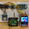
If you made it to AVC this year, you probably got a chance to see some robot fighting! Our arena had locking doors, LED lighting, hazards, big 7-segment displays and a control panel. If you didn't make it out to the event, skip through the recorded feed (Sparkfun AVC 2015 Recored stream, 38:27) to see the arena in action.
I volunteered to help run the battle arena. Unbeknown to me at the time, this also volunteered me to help build the battle arena – not that I had any objection. This post shows the process that went on in order to develop the control system.
Initial Specification
Our resident battling robot expert Casey was buying parts and attaching LED strips to the arena in the weeks leading up to the event. Being a maker I wanted to help out, but I had no idea what the master plan inside Casey's head was. On the Monday before AVC the arena was coming together, so I asked Casey, "So...how is this stuff going to be controlled?"
And he drew me this:
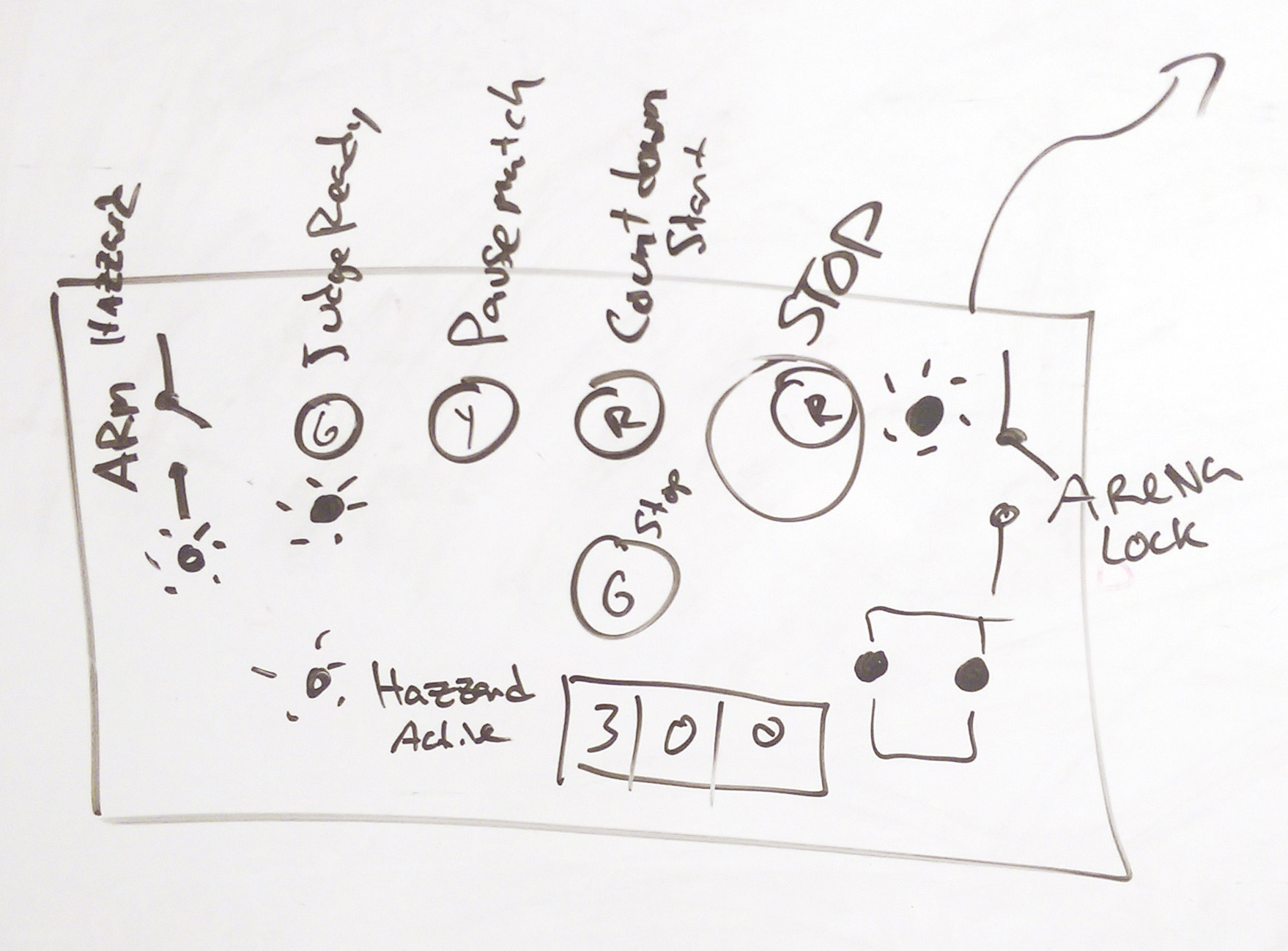
After a bit of conversation, I found out that the arena and its switches, LEDs, buttons and hazards would be driven by a microcontroller, and that the judges would control the thing through a panel. We decided that it was probably not the best idea to run bundles of parallel wires from the arena to the panel, and that we could send serial and transfer the complexity into code. We agreed on a topology where the arena would control all the peripherals, and the controller would be basically dumb, and function as an IO unit for the arena.
Building the panel
My conversation wtih Casey was very brief and my knowledge on battle arenas is quite limited so I decided to lay out a panel and show it to the customer (Casey).
First, I gathered all my materials from our warehouse and measured them. Then I created a 'master' shape layout using OpenOffice Draw, a surprisingly useful (yet aggravating) vector tool.
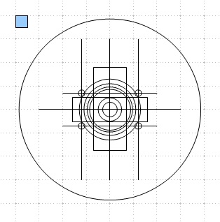
This is all the shapes in the panel about the same origin. I found the blue 'fiducial' in the corner allowed me to stay on grid and have a handle to grab objects by. This 'master' shape was copied for each component type and pruned off the other shapes.
Then I drew the thing out, making use-case assumptions about button spacing and layout.
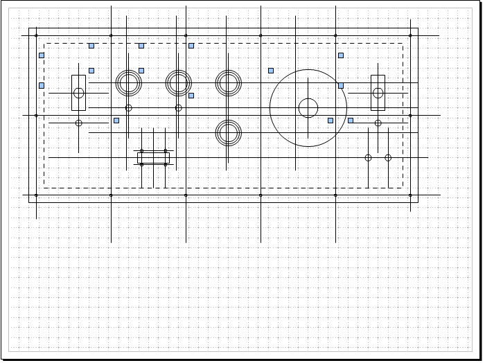
The master layout. The guidelines and handles are removed before cutting
The next step was to show the customer. This brought to light exactly how big that giant e-stop button really is, and gave a sense of proportion.
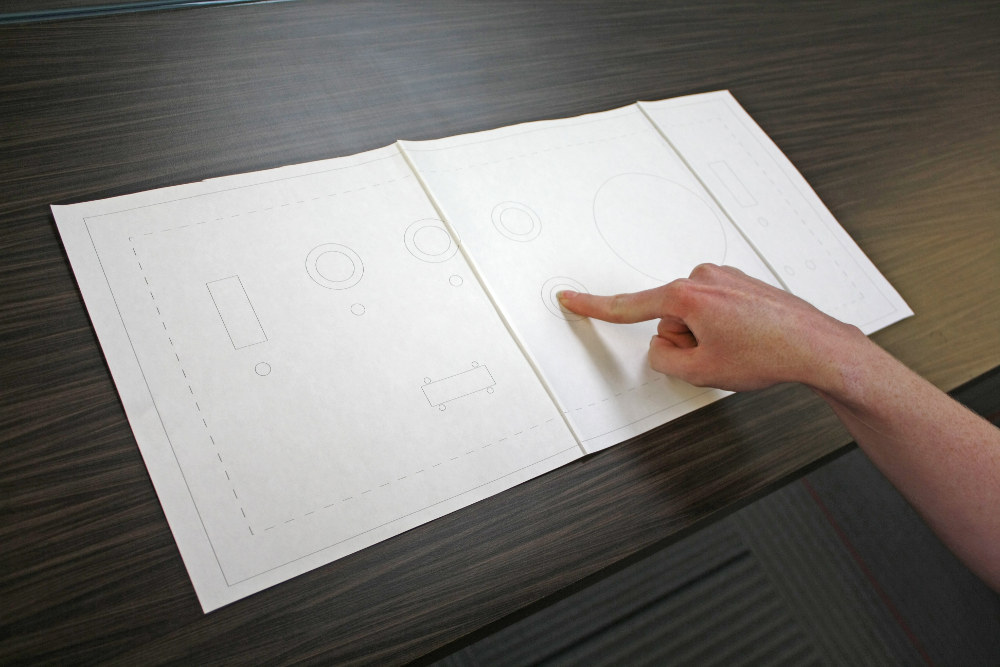
The 1:1 scale model
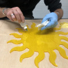
After Casey verbally signed off on the prototype it was down to our Epilog laser cutter. I cut the shape, built a 1x4 box for the edges and assembled the panel. Last minute I decided to try combining raster etching with cutting in the same print job, which was a mistake. Because the model didn't have text, no one reviewed the design and the "TAP-OUT" section was mislabled – it should have been labeled "COUNT-OUT."
Electrical assembly was very straightforward. Wires were attached to the buttons, the RedBoard was sticky-foam-taped down, and wires attached as orderly as possible in the chaos of proto-development.
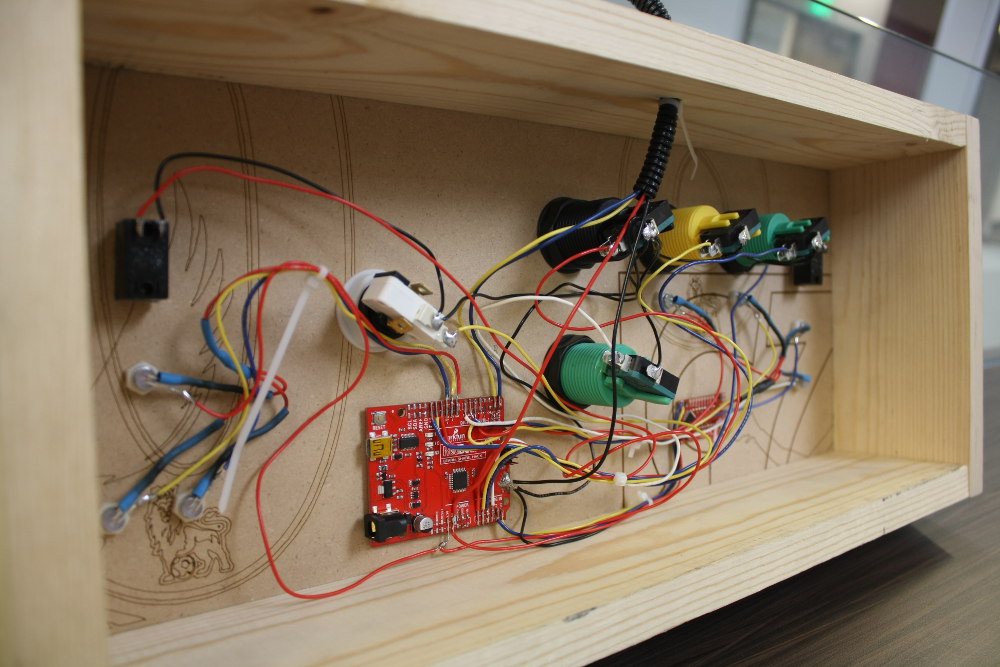
This wiring looks like a rats' nest because it is. Like wires are bundled, but really the organization of the wires was very elementary. A few things to notice: The RedBoard's sockets were removed for SMT wire attachment, the LED's current limiting resistors were in-wire with heatshrink, and the buttons were common-ground, acting as pull-down switches.
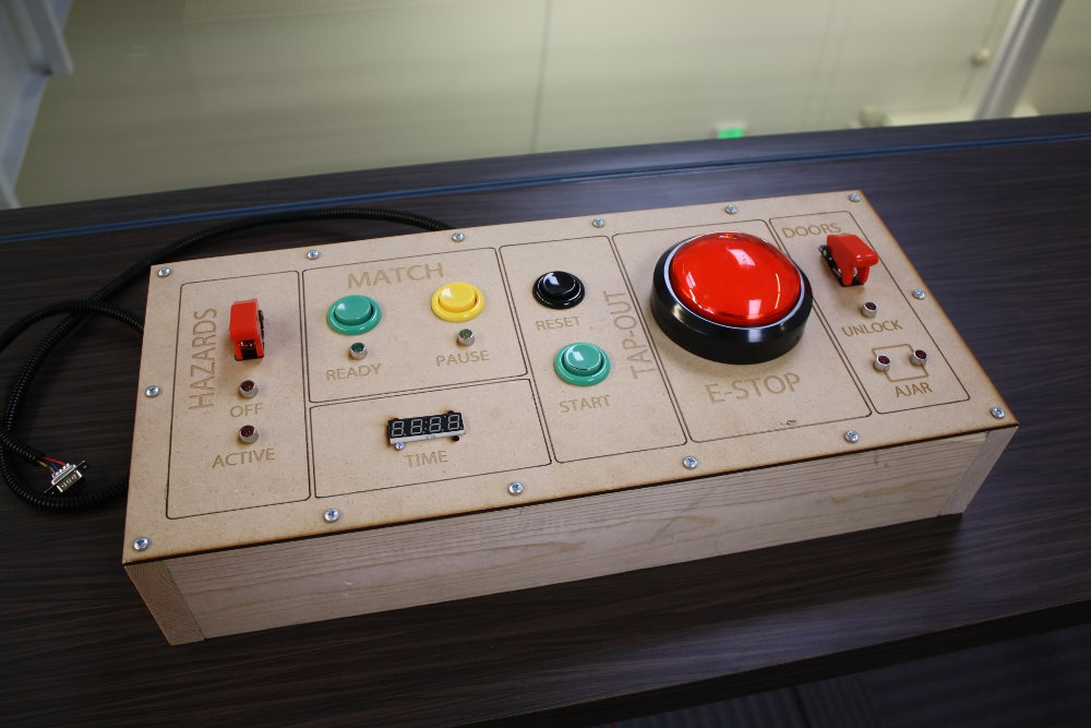
The assembled panel! Notice that text centering isn't perfect. The laser cutter's computer had a slightly different font set; next time I'll plan to adjust these at the cutter before sending the job.
Programming
High-Level Topology
This was the first time I'd ever created a battle arena for robots, so the function was completely foreign to me. From what I've seen on TV I knew there was a match time limit and, at some point, the hazards turned on. Instead, I started by drawing a top-level diagram of how the electronic systems operated, to the best of my knowledge (if I don't know how something will be, I generalize – when starting it's much more important to draw a box with a "?" in it than to get bogged down and do nothing).
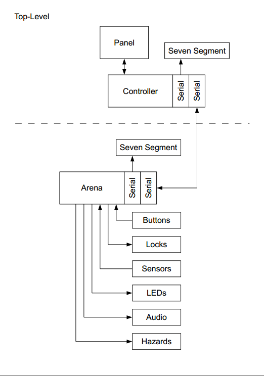
The system consisted of two parts. Above the dashed line is the judges' panel, made of buttons, LEDs, switches and a 7-segment display. Below is the arena itself, which drove the LED strips, hazards, buttons and LEDs, read button states and door states, and had a mirrored 7-segment display. The two were joined by serial link.
At this stage we had a classic "A magically connects to B" scenario. Using the knowledge that Arduino serial streams like to be ASCII oriented, I developed a system of using ASCII alphanumeric representations of raw data on the serial stream, rather than trying to send raw data. Actually I used code from the Teensy 3.1 XBee Adapter GitHub that I had previously written to jockey button data over wireless in a simple ASCII packet. I wouldn't have been able to complete this project in time without re-using code I previously developed.
To ensure I wouldn't code myself into a hole, I specified the format of these ASCII packets in a document.
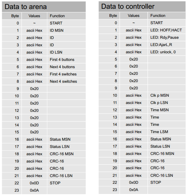
The packet specification. The ASCII packet uses tilde (~) to indicate the beginning of a packet. Data takes the form of ASCII Hex values and thus only represents 4 bits, so MSB becomes MSN, the most significant nibble. The packet is of known size and has slots for CRC and packet numbers, though neither were implemented.
Here's an example of a packet I sent to the controller in order to test the functions:
~9555 A432100BEEF
Controller-Side Design
The controller had two main functions:
- When a button changed, it sent the packet
- If a packet came in, it changed the LED and 7-segment states
Now came the real work. I needed to answer the question, "How do I make the program?" Again, I drew generally. I knew there was a serial stream that drove the 7-segment displays, so I just made a box with "Serial" in it (this could be SPI, I2C, or UART, I don't really care). It solved that problem in my mind though, so I drew it and moved on.
(I ended up driving the 7-segment with I2C.)
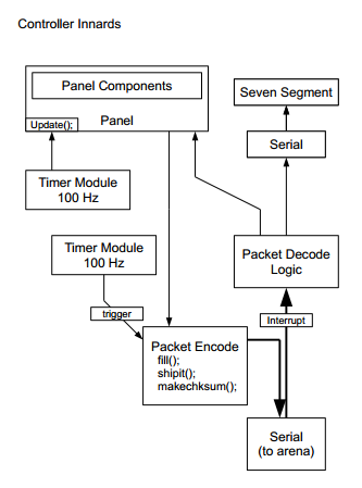
The controller topology. Loosely, a box is a C++ class. You can see that the Panel class contains the Panel Components class, though it's not 100% accurate. "panelComponents.cpp" is actually a file that that contains button, knob, LED, and switch classes that become members of the Panel object for each physical thing on the board. Again, the value of the diagram is in straightening out how the code will be assembled, not the details.
Having drawn the document, I knew what modules I would be bolting together to make the thing work. They were:
- Panel -- a basic container for panel components
- PanelComponents -- definition of panel LEDs, buttons, knobs (none in this project) and switches
- timerModule -- a class that generated a sort of call-back, sourced from an interrupt-driven timer
- 7-Segment Serial Display drivers -- Implanted into the main sketch
- Packet driver from the Teensy 3.1 XBee Adapter -- implemented into the main sketch
Basically, these were all things I've used before in other projects. Programming became an excercise in making up new names for all the objects, as well as ironing out code I never thought would see the light of day again.
One thing I did have to code fresh was the LED drivers. I already had the panel components included but never needed the LED object. I duplicated a button to start with and coded it to display on, off, or flashing. All LEDs inside the same panel were tied to the same flash signal, so when a group of buttons were set to flash, they flashed in unison! Things like this make me happy, as well as serve to grow my collection of code snippets.
Arena side design
While I was developing these systems, Casey was busy shifting the low-level microcontroller signals to higher voltage and current levels to drive the systems of the arena.
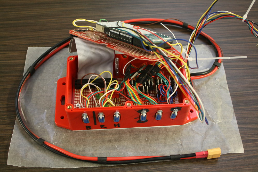
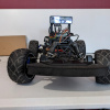
The arena control box -- with waxed paper to protect the sticky side of the foam tape.
I didn't have access to that box or to the specifics of how the peripherals were attached, so I had to make do with a dummy arena, consisting of an Atmega 328p RedBoard with a serial link. This was a situation where I had absolutely no idea what the target was going to be, but I had to work anyway. I developed a topology that showed the elements I knew would exist, and worked from there.
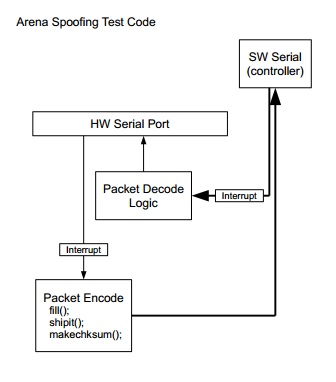
The test arena topology
From the diagram, you can see that that the program interfaced the serial monitor port of the development computer and the controller. Now that I had working controller code in hand, I re-used the packet logic directly and had decently quick success in getting this implementation to operate.
The challenge of writing the code for the arena was the state machine that made the arena operate as the battling game. I really thought of this system as the type of thing you would expect from an arcade game, partly because it used arcade buttons, but more because the UI was very call-and-response oriented. I did a thing; the arena responds.
Using the basic ideas I talked about in my last post, State Machines: blink.ino learns to snooze, I guessed at a state machine that would operate as Casey and I had been talking about.
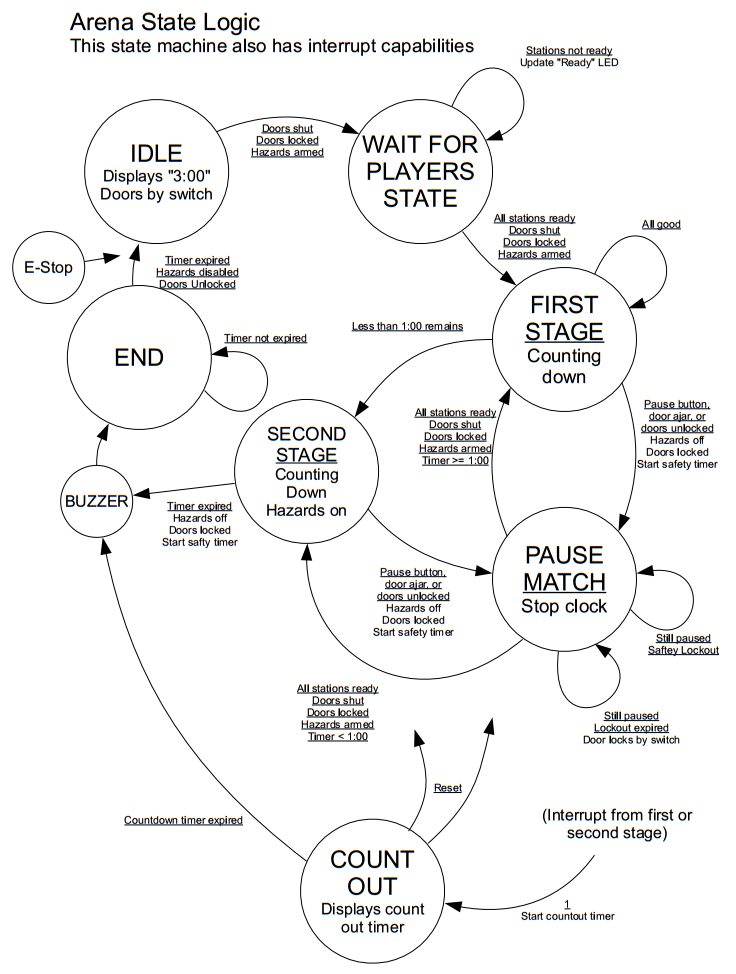
The state diagram
Now, this is a super odd state diagram. I've noted that this state machine also has interrupt capabilities, it's not 100% defined, and there are a few states just hanging out or not directed back to anywhere in particular. For instance, I knew the E-Stop button should drop everything and go back to idle. Well, I knew there needed to be an E-Stop function, but I wasn't really sure where it would go. There's a buzzer state yet the arena had no buzzer, so that was dropped. Again, it was a case where I wasn't ready to plow into code but I needed to mark down some of my ideas, and this state diagram was the result.
Truth be told, I think the "Second Stage" was dropped altogether. I went through three iterations with Casey where I ran the code and asked him, "Is this how it's supposed to act?" I never got lost working on the first iteration because I had a map, and it wasn't very difficult to modify the operation after the base state machine was functional.
When the arena controller was complete, Casey passed me off a list of IO pins. I hooked them into the code, targeted the Mega rather than the Uno, re-mapped the SoftSerial to a spare hardware UART, and the code ran. I didn't even have to change my interrupt routines; the port naming convention is standard between the two microcontrollers.
Finally, here are the modules that were rolled into the arena controller's code:
- Panel -- a basic container for panel component
- PanelComponents -- used for the player buttons
- timerModule -- a class that generated a sort of call-back sourced from an interrupt-driven timer
- Large Digit Driver modified drivers -- these large 7-segment displays are really cool
- Packet driver from freshly completed controller -- implemented into the main sketch
- Arena state machine -- class containing the state machine logic
Lessons Learned
Plan for code re-use -- You never know when a project you're working on will need a piece you've previously used. Writing modulular code and keeping it maintained in a working project folder will allow you to save time and effort over and over again. My timerModule class makes it into pretty much any project I do, to the extent that I ported it to Teensy and now maintain that too.
Document a plan for development -- I never felt bogged down with that uneasy feeling that I'm just digging myself in when working. I always had a target and that kept me sane. (Ok, I dug myself in a bit around the 4 a.m. hour Friday night, but I don't have clear documentation for that part of the project so it's no surprise.)
Proof your text with the customer -- Save yourself the embarrassment.
Check your fonts -- When using CAD software with fonts, make sure the fonts are identical to the ones on the computer that is going to be doing the control. This actually comes up now and again with PCB layout. Sometimes the way our computers render the boards is different from the fab house. Sometimes the difference is a short circuit.
Don't ask Casey if he needs any help -- I lied, I would ask him again twice over.
Conclusion
There's a couple kinds of "making" in my mind. There's "making to accomplish," and "making just to see if you can." The latter seems a bit useless, but all the things I discovered while just trying things out for fun became the building blocks when it was time to make for accomplishment. The panel construction method, code modules, documentation – and basically everything – were a re-use from previous projects.
The entire time I was writing this post I debated releasing the code (rather, telling you the location of the open-source code). I decided to allow it into the wild with the following disclaimer.
Disclaimer: The following repository has not been polished since AVC, and may not be until Casey gets a new chamber that needs a controller, at which point this disclaimer will be removed.
Happy making!
Marshall


What tool did you use to produce the Arena State Logic state diagram?
I used OpenOffice.org Draw.
The hard part was making the first arrow, something about the right-left clicks didn't go so well. Once I had one stylized I just copied and modified it.
The document is in the github repo, RAW link: architecture.odg
I was hoping it was a bit more specialized to the task...
Always on the lookout for good tools.
If you need to do timing diagrams, you may wish to check out this tool: http://wavedrom.com
I checked out wavedrom -- pretty sweet!
I've thought about programming a state machine manipulation program (maybe it could even generate code..). In my mind it's a slick java or web application that allows states to be moved around, and the arrows would automatically track to the states. It's pretty far down on my projects to-do list, but now that I know more than just myself has interest in it I may escalate it. If I do, you'll see it in a post.
I was hoping it was specifically for state machines as well. I always draw them on paper and then end up reworking them so many times I wish I had a proper tool for the job.
You might want to give Dia a try. It's freeware (open source I think, but could be wrong) and is for drawing Diagrams. It might have the symbols you need.
+1 for Dia. It can create state nodes with arrow line attach points. When you move the states, the arrows stay attached.
Here is an example of a PNG I exported from Dia.
https://github.com/onebeartoe/photorama/blob/master/documentation/lcd-menu-workflow.png
One more lesson learned for you:
If you can't justify an AutoCAD sized purchase (especially for just a handfull of projects), might I suggest Draftsight? It is the best free software for 2D CAD that I've found based on my 2D CAD training on AutoCAD. It is developed by Dassault Systemes (the same company that does SolidWorks), and is free as long as you don't expect official customer support. But, their (public) forums are pretty good for unofficial customer support.
You should consider using interposing relays driven by a latching e-stop for the power distribution for the hazards if you ever make a rev 2. This way hitting the e-stop cuts power to the hazards in the event of an emergency or controller failure.
At some point yes, a safety relay or real E-stop is necessary. For this arena if anything goes wrong the door latches remain un-energized. No one gets in unless those are activated.
Marshall, your lessons learned are spot on to what you should be doing when having any engineering project. It does nothing but make your life easier, especially in the future.
To all those hackers/makers. Follow his lessons learned and your life will be so much easier when it comes to debugging problems and communication issues/situations with either a customers/teammate/fellow hacker-maker.
Congrats on a great robot battle and hope to see it bigger and better next year!
Hey, Thanks!
I can't say what kind of arena we'll have for next year, but I'm hopeful! I can say that I'll have a robot to battle with though.