Enginursday: A new and improved IOIO-OTG!
Join us for an epic journey into design for manufacturing, voltage spike suppression, stress testing, hex file analysis and more!

We are very excited to have a new version of the IOIO-OTG available. It includes some improvements to the power protection circuit and firmware updates. In this blog we will tell the rather lengthy story behind all the challenges and solutions discovered during the revision process.
If you are new to the IOIO (pronounced yo-yo), it is a nifty piece of hardware that lets you combine the functionality of an Android device (tablet or phone) or a PC/Mac with that of a microcontroller. You can write your own application (in Java) and directly control the I/O functions on the IOIO board.
From vision-guided rovers to motor-controlled marker caricature booths, there are some truly amazing projects out there using this board. Check them out at Ytai’s Pinterest page here.
The latest hardware and firmware can be found here.
Power Spike Suppression
We heard from Tech Support that the IOIO-OTG (v21) had been failing for some customers. The failure was related to the fact that they were using long power supply cables at voltages close to the upper limit of the IOIO. We didn’t see this problem in production because all of our functional testing had been done with shorter cables.
It turns out that the on-board switch voltage regulator was failing when it saw large spikes on the “VIN” line. These spikes were only present when using longer supply cables, due to their higher inductance. Ytai Ben-Tsvi (the outside collaborator on this product) and the engineers at SeeedStudio came up with a clever solution, using some fairly cheap parts to clamp down on any spikes over 15V.
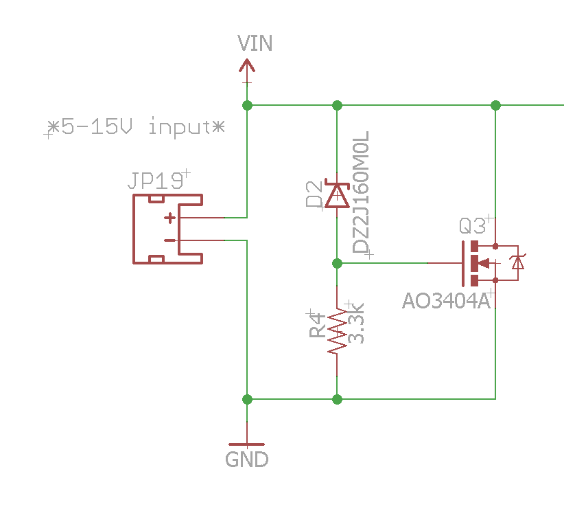
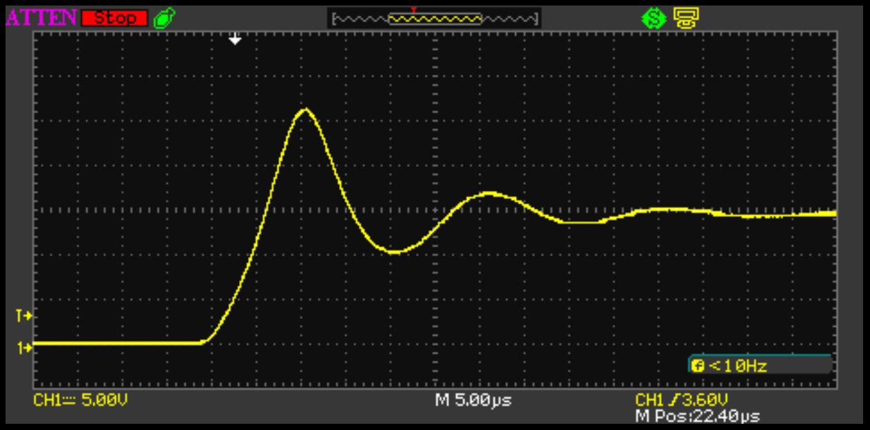
To test this out, we threw some spikes at it and took some screenshots of the scope:
Some details about the test setup:
Three-foot power cable from power supply to IOIO JST connector.
Power supply set to 15V. The MAX current available on the supply was set to 1A.
Wired a SPDT switching VIN between GND (power supply GND) and 15V (from power supply). It is important to note that it is switching to 0V (not just floating), and this fully drains the input caps.
v21 (no power spike protection) - jumps up to near 27V!
v22 (includes the new clamping circuit) - stops at around 18V (the rated maximum being 20V) - wahoo!
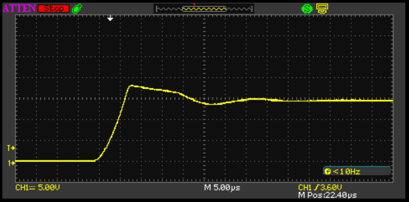
After verifying on the scope that the new circuit was performing as intended, we considered this portion of the revision complete. Now onto the other issues!
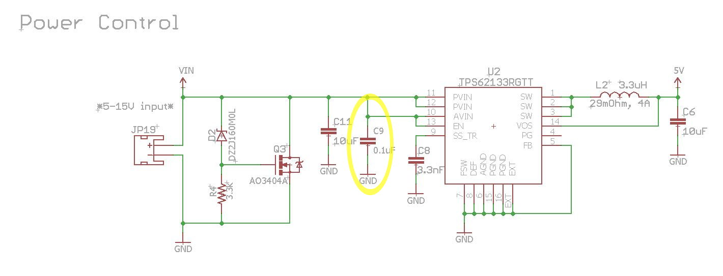
A Missing Decoupling Capacitor
Some users were experiencing failures on the voltage regulator chip when accidental large surges or shorts to GND happened on the 5V rail. It turns out we were missing a decoupling cap on the AVIN pin. The datasheet calls for this, but in our original design we overlooked this critical component. Its absence might cause the switching circuit to become unstable and fail in response to line or load spikes.
Stress Testing
In order to stress test this new circuit, we built up a jig that had four loads/test conditions controllable via push buttons:
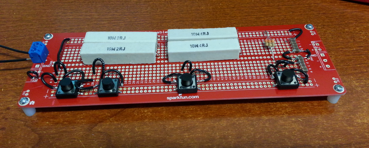
To wire it up, we used our Solder-able Breadboard. This was the first time I used this board on a project, and it sure was handy! Other parts included the Power Resistor Kit and big push buttons.
The following four conditions were used to stress test the 5V power rail on the IOIO circuit:
0Ω (short)
1Ω (over-current)
2Ω (valid high current)
100uF ceramic (i.e. very low ESR) cap with a 1k resistor in parallel (for discharge), to simulate current surges resulting from high capacitive loads, such as the ones often occurring when a phone or tablet is connected as a USB device, charging itself from the 5V supply. *A side note about this test condition: I was unable to find a cap of this value with low ESR, so I ended up doing 10 single units of 10uF caps in parallel. This would lead to an insanely low ESR, and it did the trick.
The plan was to bang on each switch several times with the IOIO connected to a high-current power supply, and change the input voltage between 5V - 15V at 2V increments.
In order to truly ensure that the test apparatus was working as planned, we put a couple of the older versions (v21) through the testing. We were able to damage the voltage regulators when using a LiPo battery as the source. Using a LiPo battery (rated at 25C) ensured we would not be artificially protecting the circuit by limiting the input current.
The prototypes tested out, but this was only three units. We wanted to have a larger data sample to truly know this fix was robust and sleep better at night. We ordered more PCBs and had production build up another 104 units. They all received rigorous stress testing, and not a single one failed. We then knew we were ready to move forward with the latest hardware: v22b.
A Mysterious Failure in Production
On bootloaders previous to version 4.01, the IOIO would occasionally have problems calibrating its oscillator during SparkFun production. Fortunately, this problem did not affect the end user, but it was quite frustrating for us in Production. After we program each IOIO board, we connect the board to a USB port on a Windows machine. It uses the very precise USB frame clock to calibrate its own internal oscillator. Sometimes this would not work properly. On some production runs, close to 30 percent of the boards would fail on first attempt. For the past couple years, we have had our technicians simply try again (and sometimes four or five times) in order for it to take properly.
Some technicians actually developed a “magic touch,” where it seemed that the right amount of pressure while plugging in the USB cable, at the right speed, while standing on one leg, would get the IOIO to calibrate properly.
We thought it may have something to do with the USB cables themselves, the USB connector on the IOIO, and/or the difference between an OTG and standard microB.
Eventually, we stumbled upon a solution that involved using a modified USB cable that terminated to an OTG-style connector. The test procedure became a three-step process, and our technicians would plug in three separate plugs in the correct order. This became known as “the magic sequence,” and worked great as a band-aid fix for the past few months.
Seeing this strange solution work 100 percent of the time led us to investigate the USB ID line. After all, this is the main difference between a microB and and OTG connector. Checking the ID line on a scope showed that it was working identically on both cables.

Unfortunately, after analyzing the readings on the scope, we concluded that it has nothing to do with the USB ID line, and so the wild goose chase continued.
Hex File Analysis
Victory is near. It’s all in the hex files.
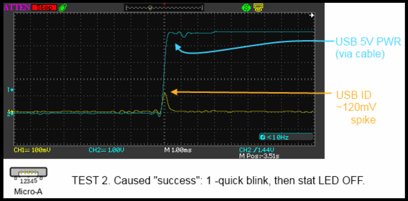
We finally exposed the problem by comparing hex files. Using a “bad” IOIO, we read the entire hex data of the micro before and after a successful calibration using the hacked OTG cable. Comparing the two hex files we see the following:
C:>fc before.hex after.hex
Comparing files before.hex and after.hex
before.hex
:10481000FFFFFF00FFFFFF00FFFFFF00FFFFFF00A4 :10482000FFFFFF00FFFFFF00FFFFFF00FFFFFF0094 :10483000FFFFFF00FFFFFF00FFFFFF00FFFFFF0084
after.hex
:10481000FFFFFF00FFFFFF00FFFFFF00FFFFFF00A4 :104820003AFFFF00FFFFFF00FFFFFF00FFFFFF0059 :10483000FFFFFF00FFFFFF00FFFFFF00FFFFFF0084
The highlighted lines above show the key difference in the hex files. This particular memory address (10482000) is, in fact, the oscillator calibration offset value. The “before” hex file is showing us a value of “0xFF.” The “after” hex file is showing us a value of “0x3A.”
One more important clue was the fact that the IOIO-OTG blinks its STAT LED at various speeds during the experiment. When plugged in at the “before” state, the STAT LED would blink at a medium pace (relative to its usual, very rapid blinking after a fresh programming). When plugged in at the “after” stage (after a proper calibration), the STAT LED would turn off.
The 0xFF that we see on the “before” hex file indicates that the IOIO never completed calibration. If we look at the calibration code, we can see that the only way to not complete calibration is to not start calibration, which would happen if we never saw the POWERED_STATE happening.
With this in mind, Ytai suspected that on the "bad" IOIOs, the contacts were such that a data connection was established at about the same time as applying power (VBUS). So, in many cases the USB state machine would advance two states at the same call to USBTasks(), and we would never actually observe the POWERED_STATE. The medium blinking pattern on the STAT LED was a result of the IOIO being in a later state, which happens to have longer code in the path of USBTasks(). Since the blink rate is proportional to the USBTasks() execution time, this was the result. So really, the medium blink pattern was the "I'm not calibrated" blink, with a "fatter" USBTasks() call in between.
Ultimately, the final solution involved just tweaking a single comparison operator in the bootloader code:

It is still not 100 percent clear why the magic hacked OTG cable worked. One likely possibility is that the mechanical design of the connector is playing into timing. OTG cables have the GND and VBUS pins offset, so they touch first. Having a little time between applying VBUS and detecting activity on the data lines may be just enough to spend at least one USBTasks() call in the powered state before advancing past it.
This might also explain why plugging in the normal cable very slowly at a certain angle might have achieved a similar result.
Either way, it came down to a very slight tweak in the code. It’s crazy how sometimes months of work will culminate in changing a couple characters. I love Ytai’s commit message: “device_bootloader: Fix mysterious bug!”
See the GitHub commit here.
Since this update, we have seen great success on the production floor. Repeating attempts to calibrate are truly a thing of the past!
Switching Graphics to Vector Designs
Another change to the design was switching all the graphics over to “vector style.” The previous graphics were drawn as millions of pixels. This leads to extremely large Gerber files, and can take even a moderately fast computer upwards of 12 hours to complete the conversion from Eagle layers to Gerbers, especially when it's a large, panelized version of the design for production. This isn’t the worst thing in the world, it just meant that we had to plan to leave the CAM job to run overnight. If for some reason it hiccuped during the night, this would delay the ordering of PCBs another day. This was also a huge headache for our purchasers. Most of our board files (Gerbers) are sent to our fab houses via email, and it’s not ideal to send an email out with a multi-gigabit attachment.
It's difficult to see in the image above, but if we zoom in a bit and highlight the polygon outlines, you can see that the graphic is truly drawn with polygons:

This change is definitely one of those things that happens under the radar. For most people, they won’t ever know the difference, but for our production and purchasing folks at SparkFun, it was a huge improvement. High fives all around!
Design For Manufacture Updates (DFM)
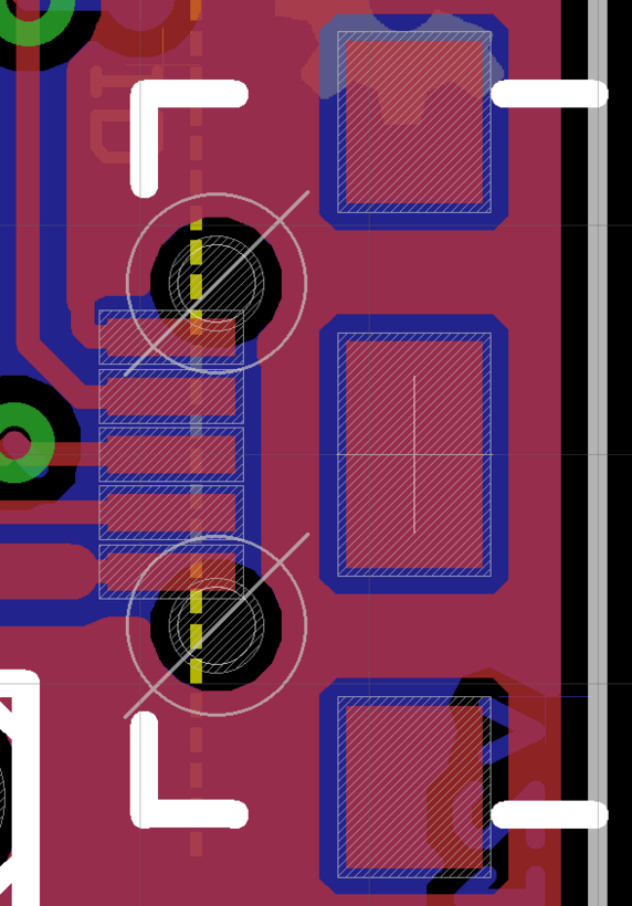
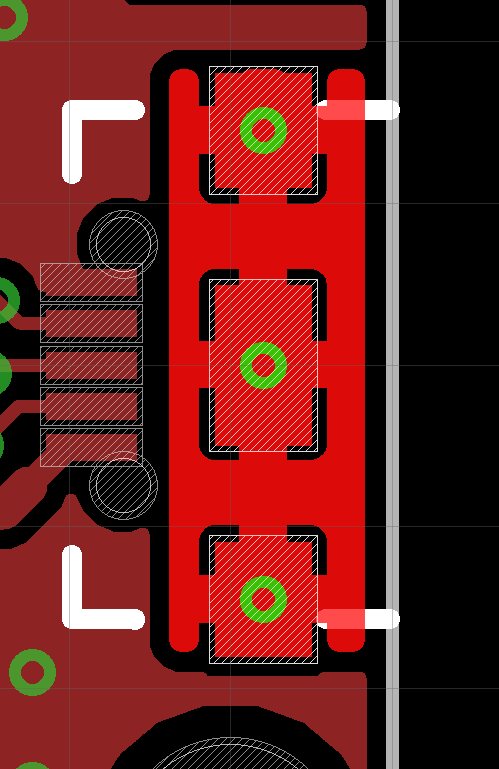
We also updated all the passive components to the correct 0603 package. We had previously been populating 0603 parts on 0402 footprints. This works, but it is very difficult for our automatic optical inspection (AOI) machine to inspect the solder fillet on either side of the component. This took some delicate nudging and re-routing in the design, but it was well worth it in the long run. Plus, who doesn’t enjoy the puzzle of a tight layout in Eagle?
Another change related to AOI was the fact that we removed the solder-mask in between each leg on the PIC24 microcontroller. Because this solder-mask is white, our AOI machine gets a bit oversaturated and doesn’t do well inspecting the lead solder bank for jumpers. Previously, we had to remove these inspection points from the AOI recipe. With the mask removed, it does much better, and we can actually utilize these inspection points! Wahoo for quality control!
We also modified the layout around the USB connector to make it more robust. The mounting pads now have “staking vias.” These allow some of the paste to flow down into the via and add strength to the SMD pad. We also included a mounting polygon drawn around the connector on the top copper. This effectively increases the area of copper holding the part to the FR4 material.
Before:
After:
Firmware Update
The firmware for the IOIO is continually improving. There is a very active community of users collaborating on GitHub. We are shipping the latest stable release of the bootloader and application. Please see the release notes for all the specific updates.
SparkFun Production is now currently programming Bootloader v4.02 and Application v5.06.
We program IOIOs with a custom eight-at-a-time programmer:
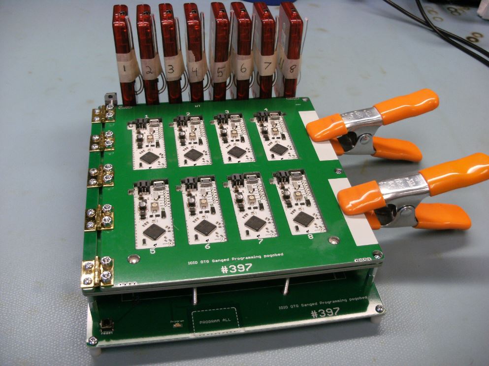
We have two of these beasts on the production floor, so it takes a little while to get the firmware updated on all 16 PICKit 3s. They work great as stand-alone programmers for PICs!
Conclusion
While working on and completing this revision, we definitely learned some important lessons:
Consider the effect of longer cables on a product, and include this potential setup during beta testing. It is always difficult to anticipate what will happen with a product once it is let loose into the wild. One might argue that it's impossible to re-create every possible scenario. To some extent this is true, but all we can do is learn from each product launch and continue to add to our list of beta testing situations. If you know of any other strange setups to consider (for the IOIO-OTG or any product use case) please let us know in the comments below.
Read, and re-read, the datasheet. More specifically, pay very close attention to example circuits. Often times, the importance of a single 0.1 uF decoupling capacitor is overlooked.
When troubleshooting an intermittent problem, keep on digging until you find the root cause. When we were tracking down the USB enumeration problem, there were times when we thought about giving up and just blaming analog black magic. It is difficult to commit more time to something when it can feel like every avenue turns out to be a dead end. Eventually, we dug deep enough and were able to find the root cause. It took a long time and involved lots of frustrating moments, but that just made the victory even sweeter! We definitely owe a big thank you to our collaborator on this product, Ytai Ben-Tsvi. Without his help and thorough understanding of the USB stack, we may have never found the root cause.
Status LEDs are very important. This was the final clue that helped us discover the root cause of the oscillator calibration problem in Production. Having a blink here or there to let you know what is going on under the hood is often a good idea!
There is ancient a balance to find when designing a new product. We must choose between "getting the thing to work" and over-engineering until you are blue in the face. Striving for a healthy amount of safety nets and user protection while still enjoying the project is what we ultimately strive for here at SparkFun. As we have grown larger, the repercussions of any mistake have grown larger too. Although you will definitely see a lot of people around here having fun, we have also learned that erring on the side of caution is often what we have to do!
We hope that you can learn from our experience with this rather lengthy revision. Maybe this story can help you troubleshoot a similar problem, or anticipate weaknesses when developing your own product! We hope you enjoy the new IOIO-OTG, and that the improvements will help you get your project to completion with minimal hiccups. If this is your first time using a IOIO, be sure to checkout the Wiki page for help getting started.


Although the described circuit adequately clamps the Vin spike, it requires 3 parts, 2 of them semi-conductors. Also, the scope shows 3,000,000 V/sec ramp rate on a 10uF cap, indicating a current of 30 Amps that the FET must divert, assuming the cap ESR is near zero. In some applications, the same spike remediation can be achieved with a small resistor of an ohm or even less. The resistor can be either inserted in series with Vin, at a small loss in run-time efficiency, or only in series with the 10uF cap, costing some input voltage ripple due to switcher current draw. Another subtle hazard when plugging a switcher to a battery is the risk of certain make-break-make contact bounce intervals that can partially charge the switcher output cap, stall during the break, and re-commence charging at the next make. If the soft-start function does not re-engage, the final charge can be violent enough to cause over-current damage to the switcher or voltage over-shoot damage to the powered components. Not all switcher types are susceptible, but it's worth checking for in design, especially as this cause is hard to diagnose on returned units.
A series resistor is indeed the simplest solution, but we have deliberately avoided, not as much due to ripple or efficiency, but more because of voltage sag. At the rated 3A load, and with USB being very picky about the tolerances of the VBUS voltage, you'd be limited to a very small resistor, which would not actually suffice to attenuate the ripple sufficiently. Thanks for the tip about the battery contact hazard. I haven't seen this failure occurring with our current circuit, but I don't know for certain that it doesn't exist. At least, I haven't seen the datasheet calling out for any precautions about input stability and it's possible that the input capacitor alone would be sufficient for smoothing out these transients enough to not throw the switcher out of stability.
Hey Geoff, Your knowledge of subtle hazards is always amazing and thanks for sharing! I'd be interested to know how we might be able to test for the battery contact hazard. Would controlling a make-break-make sequence with simple SPDT switch be adequate? From your description, it sounds like this sequence would need to happen very quickly - probably faster then I could cause manually. Maybe incorporating a micro to control a switch would be the way to go?
Also, I'd like to more thoroughly understand your in-series resistor option. Would this act like the "top" half of a voltage divider? (The resistor being the top half, and the remaining circuit beyond being the bottom half). If it were only 1 ohm, I'm guessing it wouldn't have to drop much voltage at all, and so it's current rating could be pretty minimal (keeping it small in size).
Let me know your thoughts and thanks again!
I used a certain pulse generator capable of giving me an On-Off-On signal to control a high current PMOS FET switching a high current battery source. The high currents can also flow from an adjustable supply with an output cap >> the DUT input cap. I adjusted the On and Off times looking for switcher misbehavior. Things to look for include output voltage overshoot and high slew rate of the input cap, indicating over-current. These stresses result from millisecond Off times, but only exist for microseconds. It is quite possible for the DUT to survive wounded, only to become a failure later. At least one previous employer mandates this test as part of new product DVT.
It would make better sense to use a micro-controller with a level shifter to drive the PMOS, so you could even sequence the times while watching or frame-sequence-storing the behavior.
The series-resistor option for input spike-taming (a separate problem than the On-Off-On issue) has some notes: -- It obviously must be rated for the RMS input current maximum of the system. -- The current spike connecting to a battery can be double-digit Amps, so R must be pulse-rated. Tiny metal films might erode. Composition types are more robust. -- The R value depends on the system wiring inductance and input capacitance. I've recommended 1 ohm for applications in the upper half of the input rating and had good results, but optimal for this or other systems may vary some. Sometimes I test for the minimal R capable of limiting to a safe spike peak, with the worst case maximum wire length and the source and return leads separated.
Why not use a TVS diode for the voltage clamping? That's what they're designed for. Just make sure the standoff voltage is above your max intended DC voltage and the clamping voltage is below the max input voltage of your regulator. They come in all sorts of power ratings. If the clamping voltage is above what your regulator can handle then get another regulator, there are plenty to choose from with higher max input voltages.
TVS diode was my original thinking too, and your reasoning is correct. However, in practice, if you look at real TVS diodes you'll find that they typically have a pretty large gap between the clamping voltage and the standoff voltage, which would mean that we'd have to seriously derate the max input voltage with this configuration. Using a different VREG is an option too, but again, considering different practical options and their impact on the overall board size, specs and cost, using the existing VREG circuit with an active suppression circuit was chosen as the sweet spot. I'm not declaring that this is beyond any doubt the best possible solution, only that we've definitely considered the options you're proposing and have concluded otherwise.
removed
Look at Vishay SMF15A-E3-08, standoff voltage of 15V and breakdown of 16.7V. Max clamping voltage of 24.4V @ 8.2A. Even though the clamping voltage at 8.2A is above your 20V max doesn't mean this TVS wouldn't work. This is where the engineering comes in, how much energy does your transient carry with it? Will the diode clamp below 20V can then be determined through simulation and testing. I mean props to you guys for verifying your work but did you try using a TVS diode instead of dismissing a readily available solution?
Side-note: I would also be worried about ESD blowing the gate-source junction of your FET. There's nothing to limit the voltage across the junction during a large voltage transient and since your cap is after your suppression circuit it might not help enough to save the transistor.
The other thing that you might want to consider is using a battery to power your circuit, something that can deliver some actual current. The voltage of your transient is going to depend on how much current is available to charge those input caps. If you get above 20V on your gate-source junction then the MOSFET is going to be damaged.
Another solution entirely is to use a soft start circuit for your cable length problem.
What is the issue with bitmaps? Is each pixel handled as an individual polygon so a high-enough density bitmap to avoid jaggies on angles & curves creates a bazillion polygons? (I don't use Eagle so I don't know. I'm asking out of curiosity.)
Also, I wonder if KiCAD would have made fitting the larger footprints and the subsequent re-routing easier with it's push-and-shove router? (KiCAD can import Eagle boards, but I don't know how accurately... But AFAIK it can't import Eagle schematics yet...)
What ULP are you using in EAGLE CAD for the Vector graphics. I run into the same problem using the BMP importer.
I wrote a tool in Python that creates an SCR that draws the shape in question given an SVG file as input. It's not perfect; it doesn't flatten the image, so it will draw hidden geometry, and it can't do negative space (there are easy workarounds for that, though), but the result is usually much better and much, much smaller than the equivalent BMP import.
I'm not really maintaining it much; it works well enough, most of the time, that I only change it if I discover an edge case in an SVG file that causes it to bomb out. Most of the logos in the Sparkfun EAGLE libraries were created with that tool.
I noticed you have light pipes taped to each PICKit3 module. Which LED are you monitoring? Do you have a write-up about gang programming with the PICKit3? Thanks.