SIK Project Ideas: Locker Alarm
Check out this fun project using parts found in the SparkFun Inventor's Kit v4.0.

A few weeks ago I began to share some projects using parts from the SIK v4.0 to inspire users beyond the guide book. Today's project was most certainly inspired by all of the cool back-to-schoool projects I wrote about last week – ladies and gentlemen, I introduce the Locker Alarm!
The locker alarm is a project using parts found in the SIK v4.0, so if you happen to have one at home, you are all set. The project includes a SparkFun Redboard, a breadboard, the SparkFun baseplate, the piezo speaker, a momentary pushbutton and photocell, a 330 ohm resistor, a 10k ohm resistor, and a AA battery pack and jumper wire.
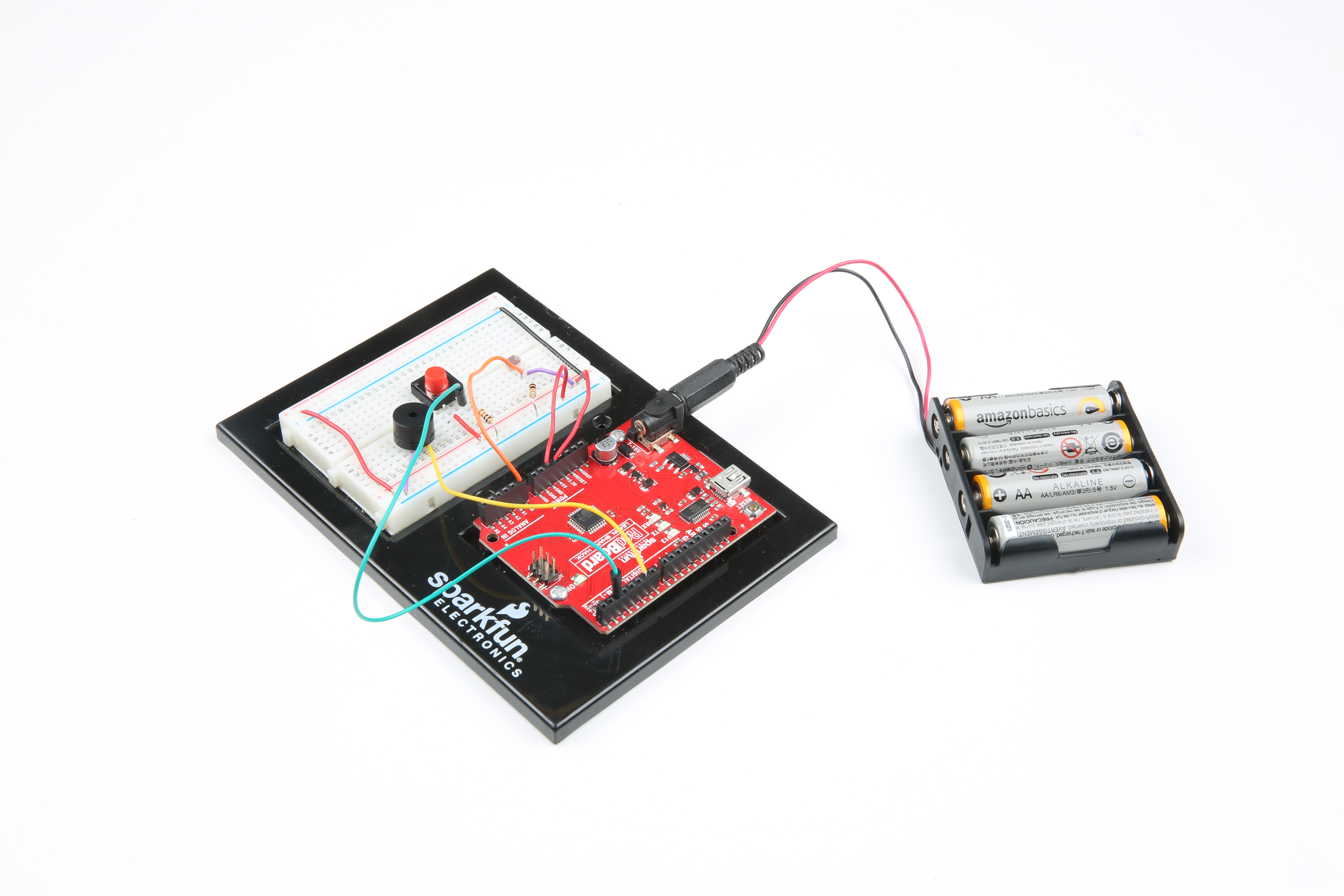
The diagram below illustrates the circuit. As you can see, the piezo speaker has two leads that are NOT polarized, meaning either can go to power or ground. In this circuit, one of the leads should go directly to ground, with the other connected to pin 6. Our next component, the button, also has two non-polarized leads. One lead will go directly to power and the second will go both to ground, via a 10k ohm resistor, and directly to pin 2. Finally we have the photocell. This guy has two non-poloraized leads as well. One will go to power, and the other to both ground, via a 330 ohm resistor, and directly to pin A0.
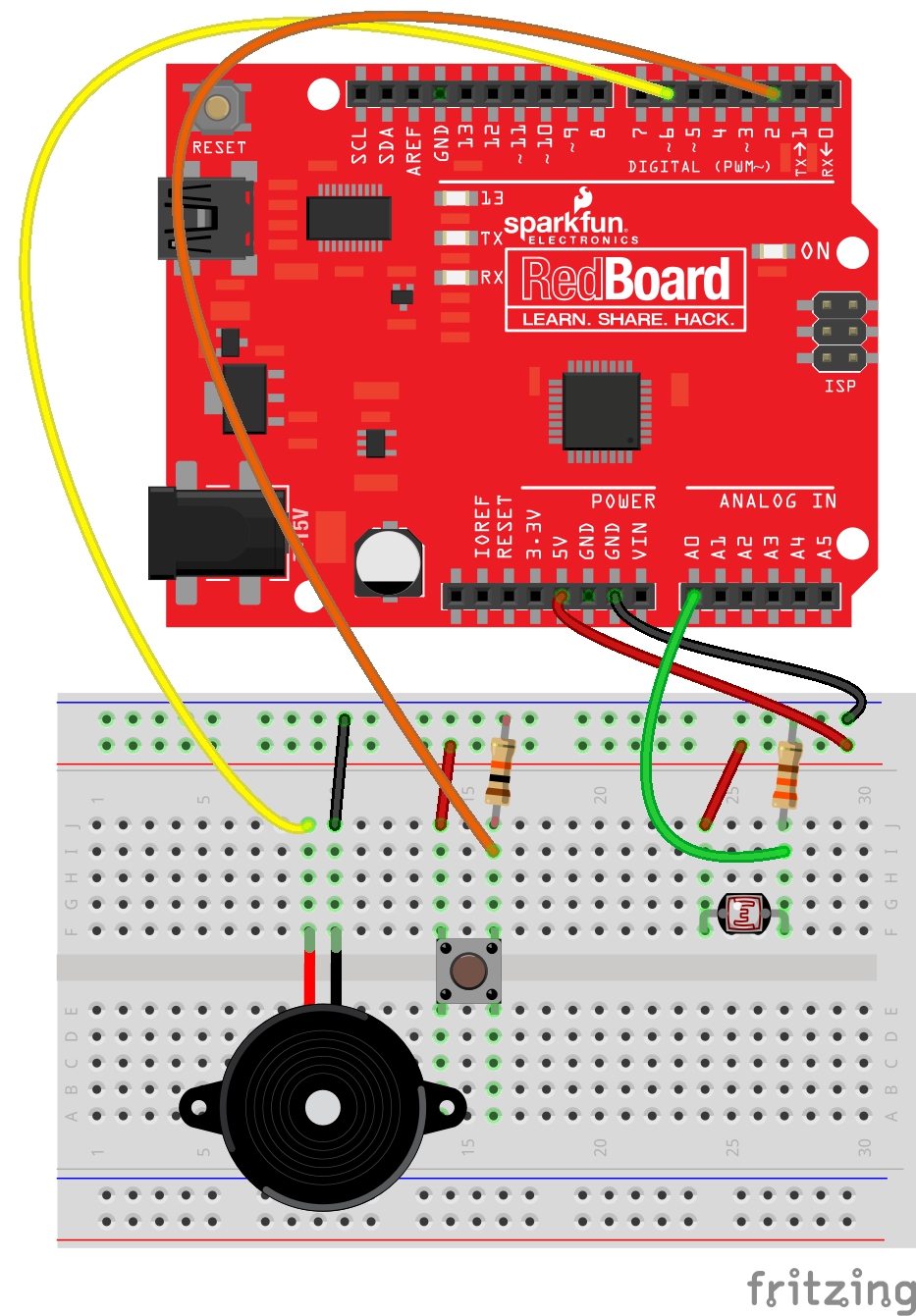
Having a hard time seeing the circuit? Click on the wiring diagram for a closer look.
Now it s time to program our Arduino. The photocell is constantly checking the light level. If it is dark, then nothing should happen because the locker is closed. If the locker is opened, the photocell will register the light and trigger an alarm tone on the piezo speaker. The button will turn off the alarm, so it might be a good idea to hide the button somewhere discreet. Once the button is hit, the Arduino stops playing the alarm tone. The alarm will not be triggered again until the locker has been closed and reopened.
You can use the program below to get the alarm running, or you can challenge yourself to write it on your own! In any case, I have added some comments to my code to explain some of the logic!
//Locker Alarm by Melissa Felderman for SparkFun Electronics September 2018

int photoCell = A0; //declare photocell to pin A0
int photoVal; //declare variable to hold photocell value
int momBut  = 2; //declare momentary pushbutton to pin 2 (interrupt pin)
int butVal; //variable to hold the value of the momentary pushbutton
int piezo = 6; //declare piezo speaker to pin 6

//the below booleans are used for the alarm logic in the if statements in the loop. Both should be set to false at the top of the program
bool turnOnAlarm = false;
bool state = false;


void setup() {

  pinMode(6, OUTPUT); //let the arduino know that the piezo pin is an output
  pinMode(momBut, INPUT); //let the arduino know that the button is an input
  attachInterrupt(digitalPinToInterrupt(momBut), alarmOff, HIGH); //attach an interrupt to pin 2(the button) we do this so the button will register even during a delay

}

void loop() {

  photoVal = analogRead(photoCell); //read the photocell value and store it in the photoVal variable

  //the if statements below create the logic for the alarm. If the photocell reads a high light value and the state boolean is false, trigger the alarm
  //this will then change the booleans 'state' and 'turnOnAlarm' to true. While 'turnOnAlarm' is true, the alarm sound will play (funtion alarm();)
  //if the button is pressed(per the attach interupt in the setup), a function will be triggered 'alarmOff();' which turns the
  //boolean 'turnOnAlarm' back to false, so the alarm will stop playing. The alarm will not turn back on even though the photocell is
  //recieveing light because the boolean 'state' is still true. This boolean will remain true until the locker is closed and the
  //photocell is recieveing no light again, essentially resetting it for the next time.
  if (photoVal > 300 && state == false) {
    turnOnAlarm = true;
    state = true;
  } if (turnOnAlarm == true) {
    alarm();
  } if (turnOnAlarm == false) {
    noTone(piezo);

  }
  if (photoVal < 300) {
    state = false;

  }


}

//below is an alarm function this uses the tone fucntion to make the alarm sound on the piezeo. This function is called while 'turnOnAlarm' is true
void alarm() {

  for (int hz = 440; hz < 1000; hz += 25) {
    tone(piezo, hz, 50);
    delay(5);
    for (int i = 3; i <= 7; i++);

  }
  // Whoop down
  for (int hz = 1000; hz > 440; hz -= 25) {
    tone(piezo, hz, 50);
    delay(5);
    for (int i = 3; i <= 7; i++)
    {

    }
  }
}


//This function is triggered when the interrupt button is hit. If changes the value of 'turnOnAlarm' so that the user
//can stop the alarm while the locker is still open and the photocell is recieving light.
void alarmOff() {
  turnOnAlarm = !turnOnAlarm;

}
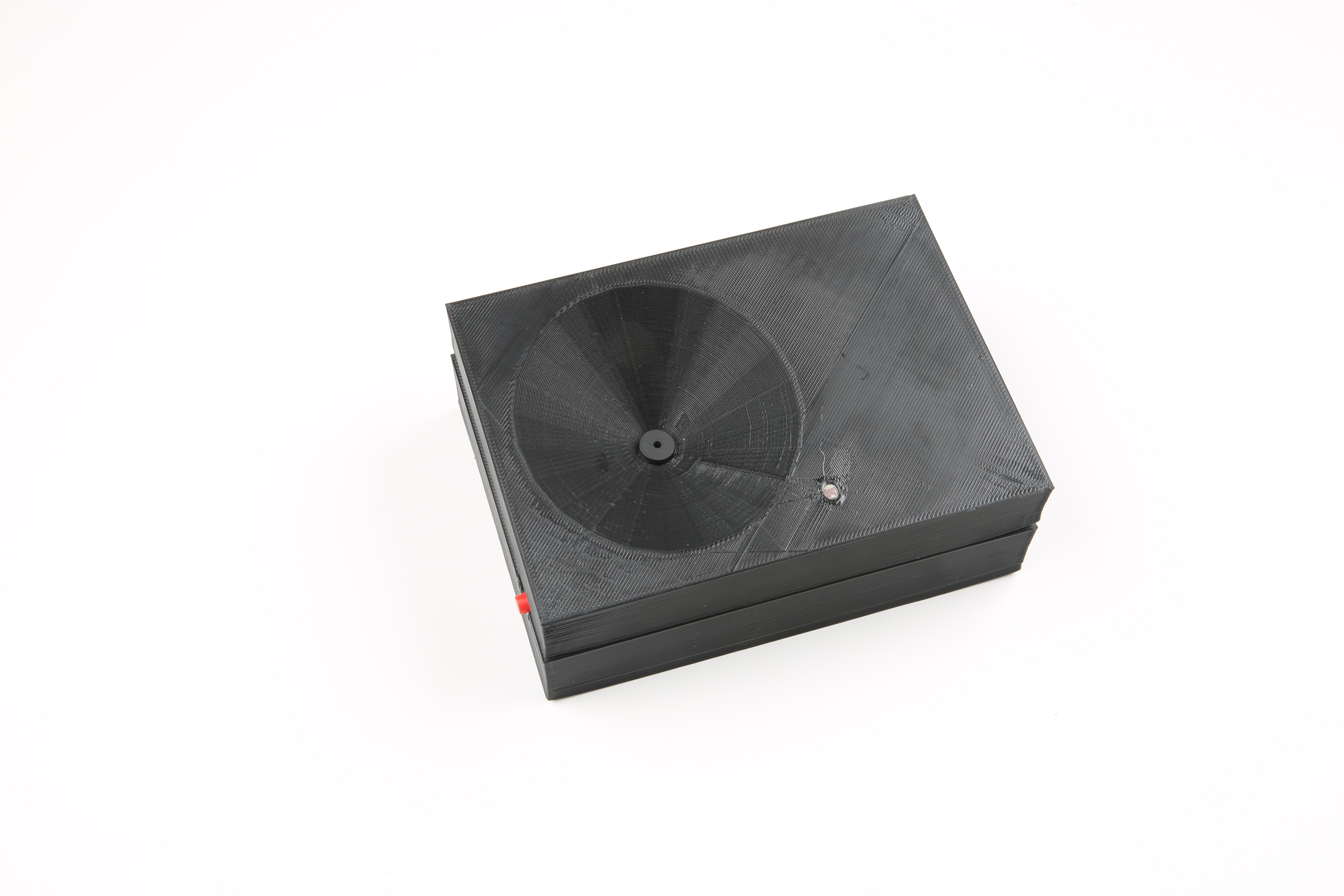
That's all it takes to make your very own alarm locker. As is, you can stick this bad boy with the AA battery pack on the inside of your locker door with some 3M foam tape, and it's ready to go. However, there is still plenty of room to take it a step further. If you have access to digital fabrication tools like a 3D printer or laser cutter, try to make an enclosure for your alarm. I made one on the 3D printer, hoping to amplify the sound of the piezo using an inverted cone shape.
For even more advanced makers, try setting an alarm that wirelessly sends you a notification of the breach. Maybe you could turn it off remotely too! This project is not limited to students with lockers - it will work in any small enclosed space, like a desk drawer or closet. There is a ton of room to build, expand and improve upon this project! Tell us know your thoughts and ideas in the comments below!


For those of us slightly past the age of having a locker, this might also be useful in the cookie jar!
I tried the code and it did not work for me. FOR ANYONE ELSE TRYING IT: If you want it to work, in the attachInterrupt, set the third parameter from HIGH to FALLING. For those who want to understand this: If the parameter is HIGH, then the interrupt will only work while the pin has high, which is when the button is push. If the parameter is FALLING, the interrupt will work when the pin goes from high to low, which is the action of pushing the button. This is all compensation for the button only having a pushed state and a not pushed state.