As a member of the Quality Control team, I am most often helping usher new PCB designs to the storefront ASAP, but on special occasions like this, I get to act as the primary engineer on a revision! What started as a simple “drop-in replacement” (famous last words) became quite a bit more involved. Join me as I highlight some of the hurdles and improvement opportunities uncovered along the way to our new, low current sensor, the ACS723!
In July 2017, SparkFun received news that Allegro Microsystems was retiring the venerable ACS712 family of Hall effect-based, current-sensing chips. We used this chip on two SparkFun products: the SparkFun Hall Effect Current Sensor Breakout and the Sparkfun Low Current Sensor Breakout.
 |
 |
| SparkFun Hall-Effect Current Sensor Breakout - ACS712 | SparkFun Low Current Sensor Breakout - ACS712 |
As both products were an asset to our sensor catalog, a revision was a must. Luckily, Allegro Microsystems had a recommended replacement chip family. With supplies of the ACS712 running out, the two design revisions were immediately re-prioritized to the top of the list, and work began.
Before any actual design work happens, it’s always a good idea to familiarize yourself with the product you're revising. Let's first build an understanding of the ACS712 current-sensing chip, then we will explore each of the designs that needed to be revised.
The ACS712 is the family of current-sensing chips previously offered by Allegro Microsystems. With the ability to measure AC and DC current up to 30A, this chip family was a great solution for many current-sensing applications. By using a linear Hall effect sensor, the ACS712 is able to isolate the circuit that is being measured from the circuit that is reading the output from the sensor, thus protecting your microcontroller. These sensors output a signal that is scaled to VCC, and with 0A flowing through the circuit measured, the sensor should output .5 * VCC. The ACS712 family is comprised of three different packages that can handle five, 20 or 30 amps. The sensor sensitivity changes depending on the sensor variation, with sensitivity decreasing as the chip’s amperage measurement range increases. In this case, we are concerned with the ACS712ELCTR-05B-T (5A variant), which has sensitivity rating of around 185mV/A measured.
Lets move on to the actual products that needed revising.
The Hall Effect Sensor Breakout is a simple breakout board that allows a user to solder wires or headers to through-holes to easily connect any of the pins on the ACS712 to an application.
The Low Current Sensor Breakout differs from the Hall Effect Sensor breakout in a couple ways.
First is the addition of an operational amplifier (op amp) circuit on the VOUT pin. The op amp and trimpots allow the user to set the VREF (voltage offset) and GAIN of the output signal, which can be very handy when measuring lower current levels as well as very slight changes in current.
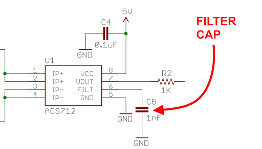
The second major difference is that the Low Current version does not break out the FILTER pin. We placed a 1nF capacitor on the filter circuit to decrease noise at lower frequency bandwidths. Unfortunately, the 1nf cap on the FILTER pin limits the bandwidth to 34kHz; the full 80kHz bandwidth can be accessed by removing this cap.
Now let's take a look at the chip family that Allegro Microsystems recommends as a replacement, the ACS723. The ACS723 family sets itself apart from the ACS712 with some additions and improvements.
The ACS723 family has even more chip options for your application, now with chips that are capable of accurately measuring ±40A. For our application we will use the ACS723LLCTR-05AB-T, which is rated to accurately measure ±5A.
Like the ACS712 family, the ACS723’s sensitivity levels are regulated by how much current the chip is rated to measure, however, all the chips in the ACS723 family now have improved sensitivity ratings when compared to the ACS712 family. In our case, the variant that is rated to measure ±5A now has a better sensitivity rating of 400mV/A measured compared to the previous, which had a rating of 180mV/A measured.
Another improvement with the new chip family is the method in which you select bandwidth and filtering. The “FILTER” pin on the ACS712 chips has been renamed “BW_SEL” on the ACS723 chips, which stands for “bandwidth select” and functions a bit differently. Instead of placing a filter capacitor on the FILTER pin to clean up the output signal, you now pull the BW_SEL pin to VCC or GND to select LOW or HIGH frequency bandwidth (respectively). The ACS723’s LOW frequency bandwidth setting limits the chip's bandwidth to 20kHz, but provides a low noise signal from the sensor. The HIGH frequency bandwidth setting allows the sensor to read its rated bandwidth of up to 80kHz, but does not provide a low noise output signal.
That about covers the major differences between the two chip families. On to the fun part of this project, the revision.
When scoping a revision for any product, I find it handy to work from a list of questions to ask of the design. This can aid in assessing the product design, quantifying the potential work needed and exploring how to make the product better. Below is a list of categories and some of their associated questions:
Product aesthetics:
- Could the silkscreen labels on the PCB be more legible or easier to interpret?
- Is there silk on both sides of the board? If not, do we want silk on both sides of the board?
- Does the product fit in with the general aesthetic of our products and product lines?
Product function:
- Is the product up-to-date with current and/or popular connectors/termination points?
- Could any components be swapped with newer components that enhance function and/or usability?
- Could any of the components be updated to use more modern, less expensive parts to lower the BOM cost?
- Could the general shape and/or design of the PCB enhance the product’s usability?
Product DFM (Design for Manufacture):
- Do we see abnormal mounting or population errors due to old landings/package designs?
- Could we re-situate components on the PCB to allow for faster manufacturing and easier rework?
- Are component landings conducive to performing fast and accurate automated optical inspections?
Design Files:
- Are all of the components in the design up to date and in the SparkFun Eagle libraries?
- Do the Eagle files adhere to SparkFun’s aesthetic?
Customer Recommendations:
- Have you considered recommendations by customers?
- Have you checked with your support teams regarding the product?
- Is the product something that customers and the community want?
It’s pretty interesting doing a deep dive on designs this old; in this case, both have been available for 10 years, and both really show their age.
We did make plenty of aesthetic and physical changes to the design, but I would like to focus on one of the larger functional enhancements, and a discovery made while testing the prototype of the Low Current version.
 |
") |
Bandwidth Selection re-thought:
Being able to adjust the bandwidth of the output signal of these chips is a nice feature – it allows the user to tailor the product to suit the application, such as reducing noise when using high gains. This is certainly a feature we wanted to extend to the user.
The ACS712 required a filter capacitor be removed from the FILTER pin for higher bandwidth operation. Removing an SMD capacitor can be a bit of a pain without the correct tools, specifically a hot-air rework station. Hot-air rework stations are expensive, and can be tricky to use for the inexperienced. On top of that, if the capacitor was removed entirely, the user would need to store or have additional capacitors if they ever wished to return the product to its original functionality.

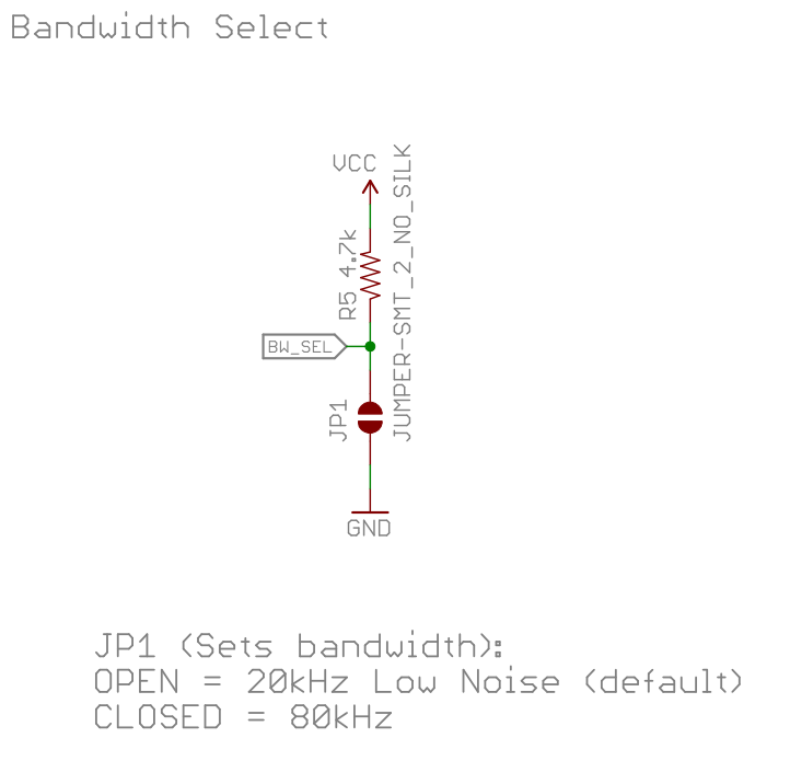
The new ACS723 Breakout (Low Current) simplifies bandwidth selection by adding a jumper and a pull-up resistor to the BW_SEL pin. This allows the user to simply close the jumper (pulling the pin LOW) to achieve a high bandwidth signal, or leave the jumper as is (tied to VCC through a pull-up resistor) to utilize the default low-bandwidth, high-filter setting. Now this board requires no hot-air rework to switch the bandwidth, and can easily be switched back and forth without having to keep track of small components.
When referring to the ACS723 datasheet, Allegro recommends the BW_SEL pin be connected directly to VCC or GND. In order to utilize a select-able jumper, I was forced to pull the BW_SEL pin up to VCC through a pull-up resistor, which was a bit of a gamble.
I wasn’t sure if the BW_SEL pin needed to sink current in order to properly function. Luckily, in testing the prototype we discovered that the pull-up resistor to VCC worked, and successfully activated the filtration cap during lower bandwidth operation. Watching the output signal with an oscilloscope, it was clear that the signal had visibly less noise when the BW_SEL jumper was left open versus being closed.
Dialing in the Op Amp and GAIN:
Now, I’m sure many of you have heard the term “drop-in replacement,” and perhaps some of you have experienced woes when interpreting that term literally. I’ve found this term is often subject to some caveats, and shouldn’t be taken literally at all. When beginning the project it was said that the ACS723 is a drop-in replacement for the ACS712; while this is true in a part package sense, the cross-over functionality is greatly dependent on the circuits around the chip. In the case of the ACS723 Breakout Low Current, some of the surrounding circuitry needed to be adjusted in order to achieve functionality similar to the Low Current Sensor using the ACS712.
The ACS723 Breakout Low Current utilizes an op amp circuit to increase the gain of the signal that the ACS723 is outputting. The detail that is important here is the mV/A sensitivity rating of the output signal. The ACS712 has a sensitivity of 180mV/A measured, while the ACS723 has a sensitivity of 400mV/A measured, giving the ACS723 a much greater sensitivity rating, and allows for higher resolution than its predecessor. When I ordered prototypes, I left the op amp components the same. This was a mistake, and not ideal for functional performance. Here is why:
The op amp circuit in the original ACS712 design has a feedback resistor with a value of 47K, while the input to the op amp (signal output from the ACS712) was routed through a 1k resistor in series with a 10K trimpot. When the trimpot was positioned to apply near-zero impedance on the input, the op amp output signal would have a x47 gain when compared to the op amp’s input signal. This seems all dandy - who doesn’t like more gain on a very small signal? Alternatively, when the trimpot was positioned to add 10K of impedance on the input, the output signal would now have a gain of about x4.27 when compared to the op amp’s input signal. This is the minimum amount of gain you can set the op amp to. So what does this mean when when you are actually measuring current? Well, if the ACS712 is outputting 180mV/A measured, that means that if you have the gain set to x4.27, the op amp will now output 768.6mV/A. If you have set the VREF trimpot so that the board is outputting 0V when measuring 0 amps, you should have no clipping of the signal of the op amp output when reading in the range of +0 to +5Amps with an input on your microcontroller functioning at a 5V logic level.
Low Current Sensor Breakout - ACS712
| Current Measured | Output Signal | GAIN |
| 1A | 0.77V | x 4.27 |
| 2A | 1.5V | x 4.27 |
| 3A | 2.3V | x 4.27 |
| 4A | 3V | x 4.27 |
| 5A | 3.8V | x 4.27 |
While measuring the highest amperage that the chip is rated for, the VOUT signal is well within the readable range of a 5V logic level micro controller, i.e. you don’t experience any clipping of the signal during reads.
Now, some of you can probably guess where this is going. When you use this same op amp circuit and the feedback resistors with the ACS723, you end up with some drastically larger output signal voltages.
Current Sensor Breakout - ACS723 (Low Current)
| Current Measured | Output Signal | GAIN |
| 1A | 1.7V | x 4.27 |
| 1A | 0.8V | x 2 |
| 2A | 3.4V | x 4.27 |
| 2A | 1.6V | x 2 |
| 3A | 5.1V | x 4.27 |
| 3A | 2.4V | x 2 |
| 4A | 6.8V | x 4.27 |
| 4A | 3.2V | x 2 |
| 5A | 8.5V | x 4.27 |
| 5A | 4V | x 2 |
As you can see, when measuring 5A you are well beyond the readable limit of a 5V micro controller. Without a voltage divider you will not be able to accurately measure up to 5A. Ideally, we want to be able to measure the max amperage the chip is capable of reading without any clipping at the minimum GAIN, without using any other hardware or components.
To fix this issue, I replaced the 47K feedback resistor with a 22K, and now the signal is back in the readable range of a 5V microcontroller. The op amp now has a minimum gain of x2 and a maximum gain of x22. This means we also get slightly higher sensitivity at minimum gain (800mV/A) versus the ACS712 Low Current Sensor’s (768mV/A).
In the end, our ACS712-based current sensors live on through the ACS723, and with updated features and performance. Intentionally, this post only covers some of the more interesting details of the revisions. If you would like to dive into the minutia, I recommend downloading all four Eagle designs and comparing them. As always, feedback is appreciated – please post any thoughts in the comments below, and if you have any revision stories to share, we’d love to hear them! I’d also like to mention that if you have any revisions you’d like to see, please post them here or directly on the specific product page. In addition to handling EOL situations like this, we are always interested in revising products to make them better. Thanks for reading, and I look forward to sharing the details of another revision sometime soon!


I just use a single iron, load up some solder on one side and bridge across the component with the tip. Never had an issue taking them off. If one side of the component is connected to a plane, that's the side I'll add solder to and focus most of the heat.
Or, if you don't need to save the cap, there's always the grab-with-pliers-and-squeeze approach.
This.
Thanks for the update on the current sensor board - I have been using the Sparkfun ACS712 5 and 20 A versions for a number of projects and they work pretty well! Two projects use a solar panel and rechargeable battery and I'm interested in the charge available in the battery, so the bipolar current measurement is a real plus. I really like the isolation between the circuit being measured and the sensor output - that's just cool. The biggest issue I've found so far is that the output is directly tied to the sensor Vcc, so having a super-stable Vcc is critical for good measurement. To that end, I was thinking of using one of those precision voltage references like the LM4040 but that compresses the available output range (I'm using a 5 Vdc ADC downstream). What I ended up doing, for one project, was using a dc-dc buck converter with a 10-turn pot and can dial in a pretty stable 5.00 volts to supply Vcc for the three current sensors in one project, and that way the sensor output doesn't move around so much. It could be very handy for these boards to have an on-board precision 5.00 volt precision reference driving the Vcc pin, and that way always know that 2.50 V output is dead on 0A. Of course, this doesn't do much good unless there's a precision reference at the ADC as well, but it would help pin one thing down at least. Many of the precision references can supply limited current anyway, and so the 10-15 mA the ACS712/723 needs would be well within its ability. I see also that there looks to be a board with large holes for the wire carrying the current to be sensed. This would be great, as I'm looking at a circuit to sense up to 30 A from a 12 Vdc battery, and the ACS712 board has only board holes that accommodate 16 or 18 ga wire. I was going to burnish off the silk screen to expose more of the pad copper, but a larger well plated hole would be even better. Thanks for the updating you're doing on this product. Makes it even easier to use!
I wish SparkFun would make a 30 amp version of this board. I'm having to look to your competition to find one (gasp!).
Hmmm... not a bad idea.
Very interesting, thanks. FYI, I noticed a typo:
I suspect you meant "sink" rather than "sync".
And regarding the trim pots, I found that they interacted with each other in the previous design such that adjusting the gain also affected the bias. Rather annoying to get the sensor calibrated.
also, I think the units should be volts rather than amps for the highlighted out-of-range items in the last table.
Also, red highlighting over black text makes the text virtually unreadable. Suggest yellow or green for better legibility.
Right you are. Both issues have been fixed. Thanks for the sharp eye.
Nice write up! Thanks for the detailed walk-through, these discussions are illuminating to the non-Engineer like myself!
One might expect that your list of questions is a part of the Design Control Process in your Quality Management System.(Sorry, i have to say that - it's a reflex.)