DIY Camera Lens Light Ring
Taking what I've learned about LED color mixing and Python, along with our LumiDrive LED Driver and LuMini LED Ring, I set out to create a light ring for macro photography that surpasses all others.

I’ve spent some time on these Tuesday blog posts talking about, among other things, color mixing, and analog and digital inputs in Python, using our LumiDrive LED Driver in combination with our RGB LED Rings. Well, I thought it was time to combine them all into one semi-useful project.
I’ve used the LumiDrive, along with one of our 3” LuMini LED Rings, to make a macro ring light.
This is a light ring that attached to the lens of your camera and evenly illuminates your subject with the light coming from the camera’s point of view. It makes it easier to avoid errant shadows when shooting close-ups. Most of them are a ring of LEDs with a diffuser lens, while some will offer an additional blue lens and orange lens, to give the resulting image a cooler or warmer look, respectively.
You can purchase an inexpensive one for thirty or forty bucks, and the results will be pretty much what you would expect from that price range. On the other hand, if you're serious about your close-up photography, you could pick up something like a Kaiser KR 90 Ring Light for just under four hundred dollars – a little more than I would spend, especially when I know I would enjoy the challenge of creating my own. Now if you know me, you know that I believe that any project worth doing is worth overdoing. So with all of the tools at my disposal, why wouldn’t I make a macro ring light that offered 16.7 million colors?
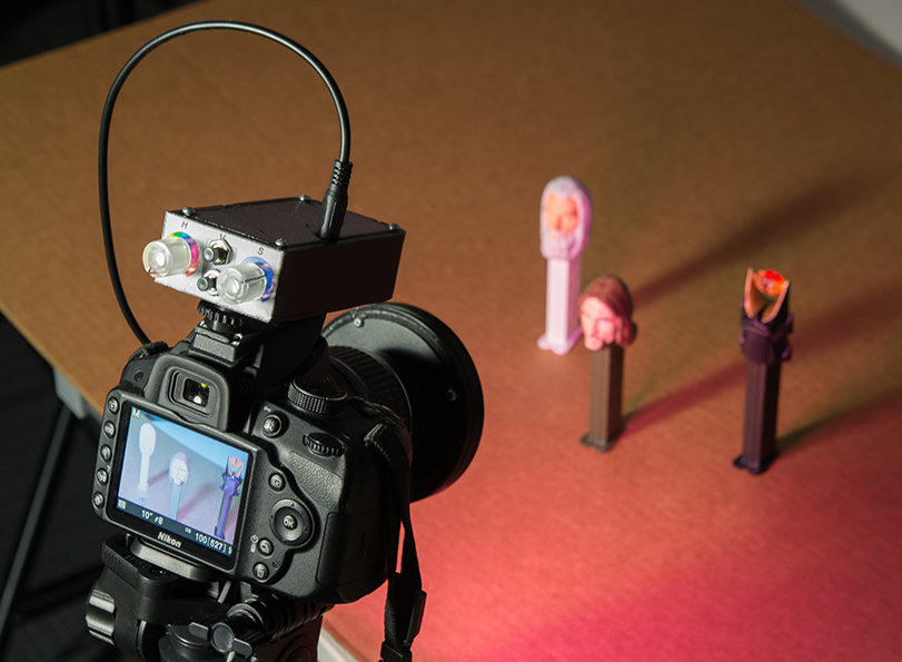
Macro ring lights give even illumination from the camera's point of view when shooting close-ups.
The idea
The last time I talked about color mixing with LEDs, I dealt primarily with RGB. This time around I'm looking at HSV. There are a couple of reasons for this. The first is simply because I wanted to do a bit more exploration into the HSV color model. The second is a bit more practical. The pins broken out on the LumiDrive consist of a pair of analog and a pair of digital. Had there been three analog pins, I might have just set one to each of the red, green and blue values. However, I figured with what we have available, I could use the analog inputs for both hue and saturation, and use the digital inputs to increase and decrease the value by small increments.
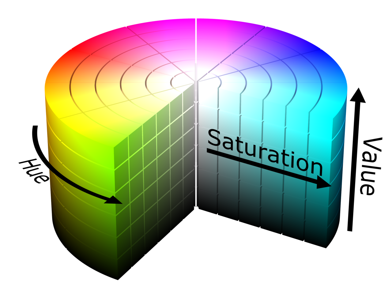
The HSV Color Space depicted as a solid cylinder, showing the travel of Hue, Saturation and Value. (Image courtesy of Wikimedia Commons.)
In the HSV color space, the hue travels around the space in 360 degrees. Saturation goes from the outside of the space, which is full saturation, to the center, which is no color saturation at all. This means that, regardless of the hue, if the saturation is all the way down, the color will show as white (assuming that the value is all the way up). The value, then, can be roughly equated with brightness.
The brains
The build is based around the SparkFun LumiDrive LED Driver, paired with the LuMini 3” LED Ring. It contains 60 APA102s, and can be easily controlled with the LumiDrive just by writing a little bit of Python code. I prototyped it all on a breadboard, just to make sure I could actually make it do what I wanted it to.
You may have noticed in my previous post that I soldered female headers into the LumiDrive to make life easier. However, once I moved from prototype to final product, I soldered my potentiometers and momentary buttons directly to the board. Also, to create a more finished look, I used a 3.5mm TRRS jack coming out of the LED poke-home connectors. Then, from the LuMini, I used a TRRS audio connector. I figured that this would make transporting the two parts easier, and put less strain on the connections at the LumiDrive end. To power it all, I'm using a 1Ah Lithium Ion Battery.
Now to make my life easier, I did cut the red (+) wire from the battery and installed a small switch to power the project on and off. I'm sure you're aware that lithium ion batteries can be twitchy, and by twitchy, I of course mean fire-y and explode-y. So if you're not comfortable with this, you can certainly adjust the top of the housing to easily allow you to unplug the battery from the LumiDrive when not in use.
The body
The two halves of the body took a bit of experimenting and trial and error. For the ring itself, after a few different ideas including variations on a 3D-printed ring clamp, I decided to use a Lens Adapter Ring for the Cokin CBP400A P-Series Filter Holder. I thought it would be ideal, but I was off by about 2mm.
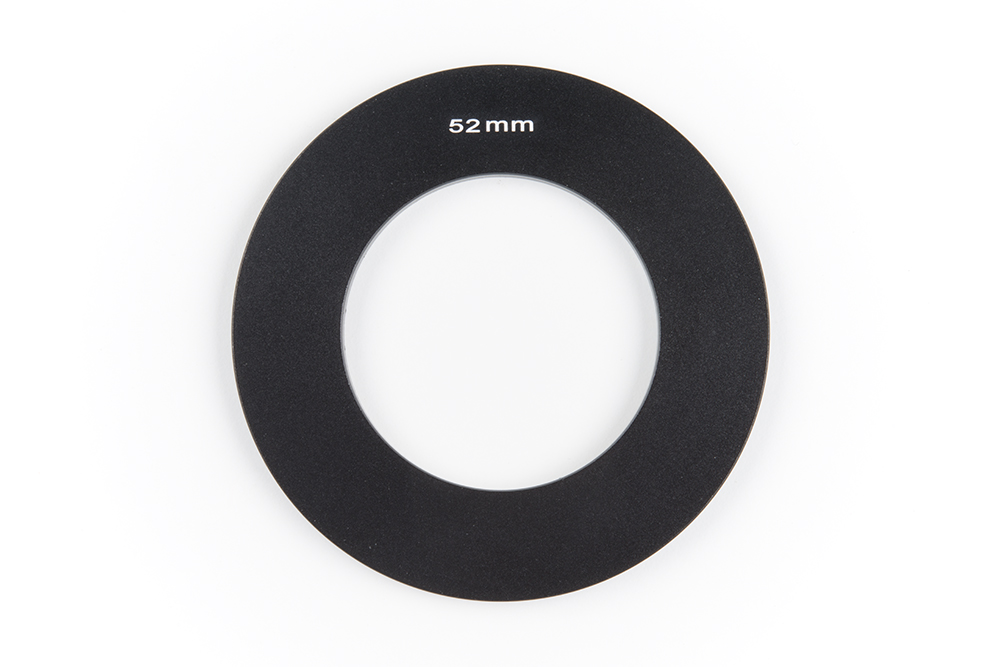
By using a ring adapter like this one, I can easily swap out whatever size I need for whichever different lens I might be using.
I wound up having to notch the outside of the ring adapter, as the mounting holes on the 3-inch LuMini fell right on the edge of the ring, but in the end, it gave stability to the entire thing. I designed and printed the ring body, realized that I had forgotten a place to run the wiring, added a notch and a hole, and reprinted. The second print worked almost perfectly, which may be a new record for me!
To add a little stress relief to the cable, and again create the illusion of a thing that someone might have actually purchased, I added a grommet. I also designed a diffuser for the front of the ring. I first printed it with white ABS, but even at 1mm, it was still too thick for the light to make a difference. I’ll try again with a clear ABS.
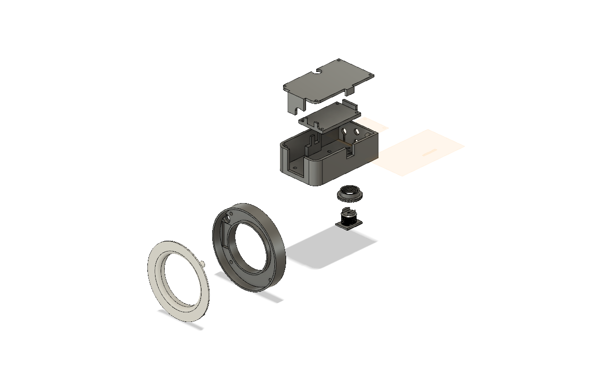
The designed parts, modelled in Fusion 360.
For the electronics and battery housing, I made it as compact as I could. I also designed it to have a cold shoe and retaining ring, so that it could lock down onto any DSLR camera. The retaining ring goes down onto the cold shoe adapter first, then the adapter gets screwed to the main housing body.
I always enjoy the challenge of figuring out how to design for 3D printers - what needs to be supported, what can't be supported, how to create and assemble two separate parts so that they can both be properly supported when being printed – all of that stuff. I added holes for the potentiometers and buttons, along with the on/off switch, and I designed the front so that an opening remained for charging the LiPo battery, as well as reprogramming should the need or desire arise, without having to disassemble the housing. I have to say, I'm quite satisfied with the design.
Putting it all together
I have to admit to having a lot of fun playing with a number of variations, not necessarily because I thought they were all possible implementations for this project, but because I like the challenge of math. Seriously, I knew I wouldn’t need a single potentiometer, whose range is read as 65535 steps, to inversely control both red and blue LEDs so that as one rose from 0 to 255, the other descended from 255 to 0, using only integers throughout the range. Setting green at 10 and controlling red and blue in opposition, this is what I came up with:
inverseColors = (math.trunc((HUEpot.value * 255) / 65535), 10, abs(math.trunc((HUEpot.value * 255) / 65535)-254))
Truncating returns integers, not floats, and using the absolute value returns only a positive integer. But I digress.
The dotstar and fancyLED libraries that Adafruit has created were paramount here, as was our LumiDrive code that Elias put together. While I have used the fastLED library on previous Arduino builds, and there are still a number of things that can be done with addressable LEDs in the Arduino environment that aren’t easily accessible using Python, these libraries and circuitPython were extremely helpful in making this happen. Here is what my final code looks like.
import adafruit_dotstar # The LED library
import adafruit_fancyled.adafruit_fancyled as fancy
import math
import time
import board
import digitalio
from analogio import AnalogIn

# Setting up the board's blue stat LED, mostly for testing
led = digitalio.DigitalInOut(board.D13)
led.direction = digitalio.Direction.OUTPUT

# Here we'll define the inputs/values for HSV
SATpot = AnalogIn(board.A3)
HUEpot = AnalogIn(board.A4)
VALval = 0.4 # Set the initial value for Value, since it's button-driven

# Setting up the digital IO pins as input buttons
button8 = digitalio.DigitalInOut(board.D8)
button8.direction = digitalio.Direction.INPUT
button8.pull = digitalio.Pull.UP

button9 = digitalio.DigitalInOut(board.D9)
button9.direction = digitalio.Direction.INPUT
button9.pull = digitalio.Pull.UP

# These two variables should be adjusted to reflect the number of LEDs you have
# and how bright you want them.
num_pixels = 40 #The 3" ring has 60, the 2" ring has 40, the 1" ring has 20
brightness = 0.5 #Set between 0.0 and 1.0, but suggest never running at full brightness
startSequence = 0 # Last minute addition to create startup sequence

# Some standard colors.
BLACK = (0, 0, 0)
RED = (255, 0, 0)
YELLOW = (255, 150, 0)
ORANGE = (255, 40, 0)
GREEN = (0, 255, 0)
TEAL = (0, 255, 120)
CYAN = (0, 255, 255)
BLUE = (0, 0, 255)
PURPLE = (180, 0, 255)
MAGENTA = (255, 0, 20)
WHITE = (255, 255, 255)

# This creates the instance of the DoTStar library.
pixels = adafruit_dotstar.DotStar(board.SCK, board.MOSI,
    num_pixels, brightness= brightness, auto_write=False)

# The travel function takes a color and the time between updating the color. It
# will start at LED one on the strand and fill it with the give color until it
# reaches the maximum number of pixels that are defined as "num_pixels".
def travel(color, wait):
    num_pixels = len(pixels)
    for pos in range(num_pixels):
        pixels[pos] = color
        pixels.show()
        time.sleep(wait)

def slice_rainbow(wait): # Just a little startup color animation

    num_pixels = len(pixels)

    pixels[::6] = [RED] * math.ceil(num_pixels / 6)
    pixels.show()
    time.sleep(wait)
    pixels[1::6] = [ORANGE] * math.ceil((num_pixels - 1) / 6)
    pixels.show()
    time.sleep(wait)
    pixels[2::6] = [YELLOW] * math.ceil((num_pixels -2) / 6)
    pixels.show()
    time.sleep(wait)
    pixels[3::6] = [GREEN] * math.ceil((num_pixels-3) / 6)
    pixels.show()
    time.sleep(wait)
    pixels[4::6] = [BLUE] * math.ceil((num_pixels-4) / 6)
    pixels.show()
    time.sleep(wait)
    pixels[5::6] = [PURPLE] * math.ceil((num_pixels-5) / 6)
    pixels.show()
    time.sleep(wait)

# Here's where the action happens
while True:
    if startSequence == 0: # Startup with a quick color animation
        slice_rainbow(0.2)
        time.sleep(0.1)
        travel(BLACK,0)
        time.sleep(0.5)
    startSequence = 1 # Stops opening sequence from continuing to run

    if not button8.value: # Increases the Value in increments of 0.05
        VALval = round(VALval + 0.05, 2)
        if VALval > 0.8:
            VALval = 0.8 # Limit Value (brightness) to 0.8 to avoid meltdown
        time.sleep(0.05) # Debounce
    elif not button9.value:
        VALval = round(VALval - 0.05, 2)
        if VALval < 0:
            VALval = 0
        time.sleep(0.05) # Debounce

    print ("Value value = ", VALval)
    TRYME = fancy.CHSV(HUEpot.value / 65535, SATpot.value / 65535, VALval)
    packed = TRYME.pack() # Converts HSV into HEX

    pixels.fill(packed) # Sets color to given HEX value
    pixels.show() # Illuminates LEDs

    time.sleep(0.01) # Debounce
The result
I created a graphic so the user knows about where they are with hue and saturation, and which way the value buttons adjust.
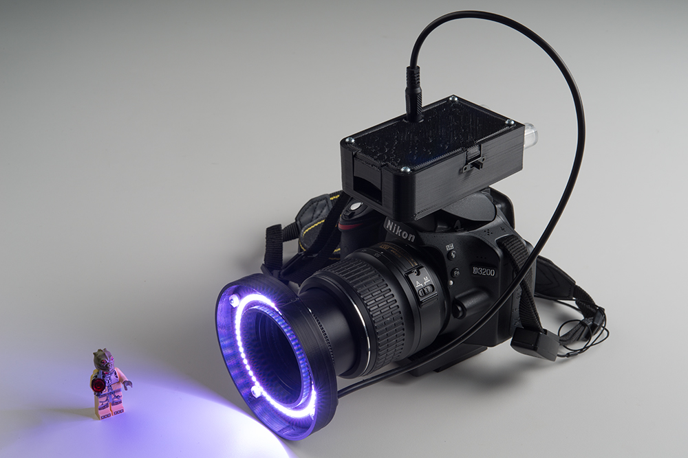
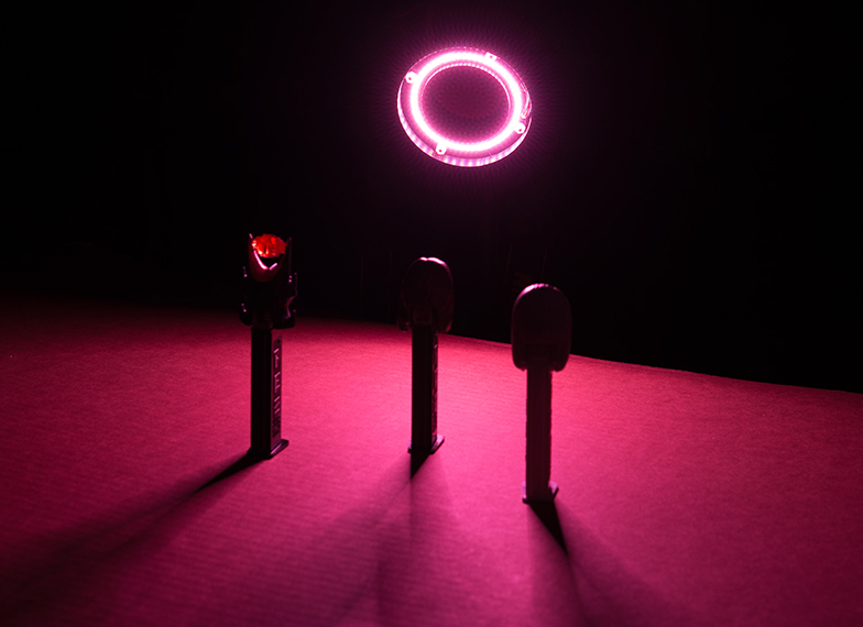
The diffuser didn't quite make it in time to go to print, but the results are still quite even. Notice it also works on tiny Star Wars characters.
I have to say, I’m very happy with the end result. Now admittedly, since I am adjusting the value incrementally, I am not able to create the full 16.7 million colors originally advertized. However, it does everything I wanted it to, and does it all quite easily.
It’s very user friendly, although I do see some possible issues and changes to improve or customize it as needed. Perhaps you find a color that is absolutely perfect for your needs. That’s great if you never change from it, but what if you want to recall it later? What if you find half a dozen colors that are perfect for half a dozen different types of shots that you frequently repeat?
Maybe you do a little reprogramming so that the value always remains constant, while you can still adjust the hue and saturation, and you re-purpose the buttons so that one saves and enumerates your favorite colors, and the other recalls them. Or perhaps you want to add more visual interest to your shots by illuminating only one side. Maybe each button controls one half of your LEDs, so you can light left side only, right side only or full illumination. I’d love to hear any ideas, variations or improvements you may have on this, or the builds and ideas that are swirling around in your heads. Let’s face it, we learn this stuff so that we can make cool projects, right?
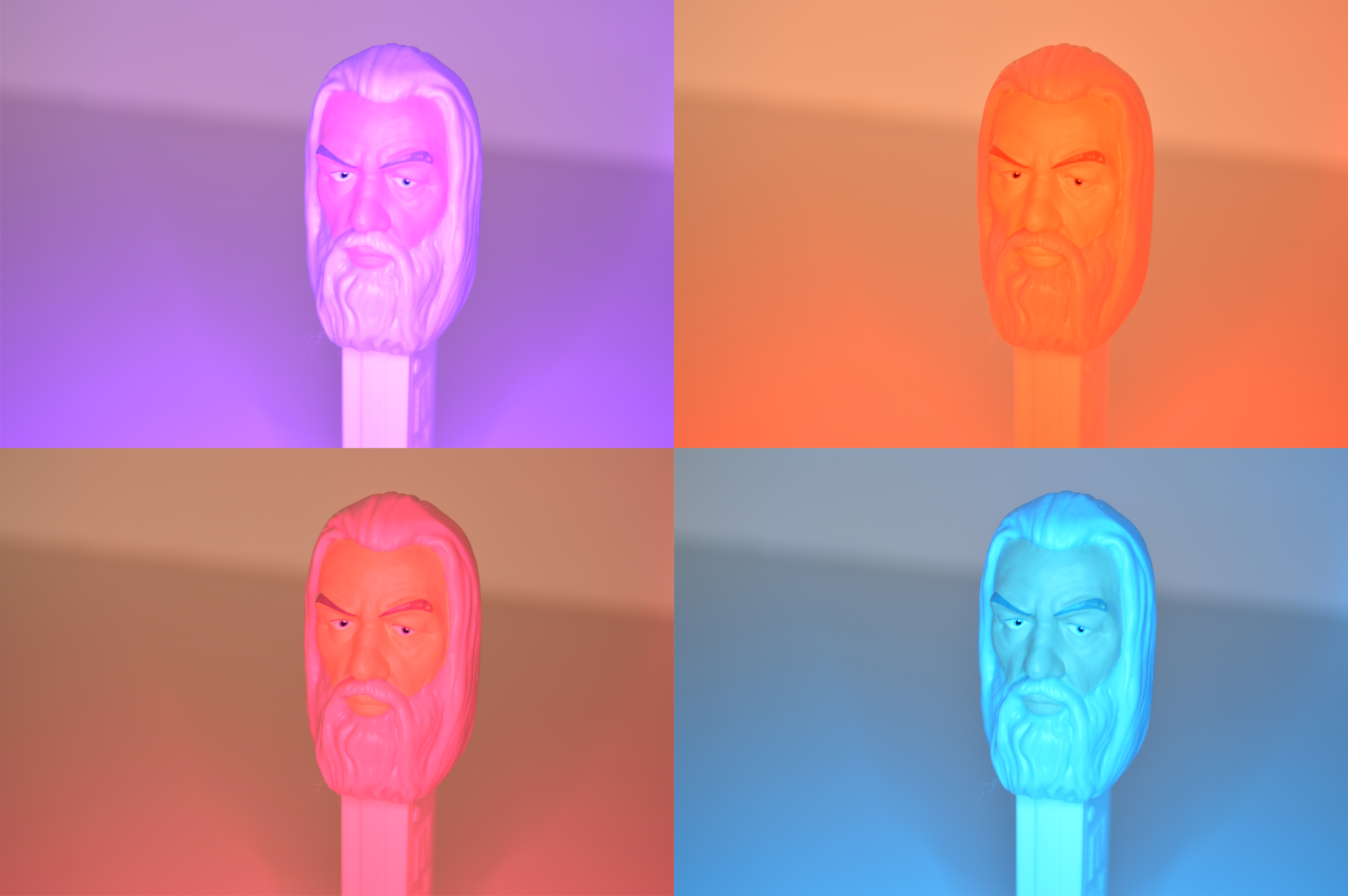
Completely alter the feel of your images through the lens by making simple adjustments, without a photo editor. How Warholian!
I've put the .STL files, along with the code and the graphic, up on GitHub. If you're interested, you can find them all here, and the full wish list of parts below.
Interested in learning more about LEDs?
See our LED page for everything you need to know to start using these components in your project.


awesome Project ROB!! we are using something similar downstairs on the reflow oven,come check it out!
This turned out fantastic. I might just make one!
Neat project, Rob!
First thought is that when I glanced at the B&H link you provided, I did notice that they say the Kaiser ringlight is "special order", and expected to take 7 to 14 days (I sure wouldn't be surprised if it took longer), while all of the items in your parts list are "in stock" (at least as I type this), meaning that if someone with a bit of skill, could be taking pictures with yours sooner than with sprining for the commercial one!
Admittedly, I didn't look thoroughly at the commercial one, but one thought about your ring light is that it could do a LOT more than at least the less expensive commercial ones. For instance, since the LEDs are individually addressable, it could be programmed to illuminate one side one color, and the other side with another color. Or if your camera can take videos, experiment with illuminating with a "moving" light.
I'd have been inclined to put the battery on an easier-to-disconnect connector than the JST connectors, so that you can have multiple batteries in your "gadget bag" -- I've had way too many times when I was in the midst of a remote photo session when the battery on some key "gadget" (including the camera!) died! (Even "once" is "way too many times", IMHO.)
I just wish tilt & shift lenses weren't so expensive... it's tempting to go back to large format film cameras...