Enginursday: Switching Sensors with a WS2811 Addressable LED Driver
Facing the daunting task of wiring together 192 of the same I2C sensor inspired a creative solution.

Sometimes we sign up to do crazy things - like going skydiving with your best friend or running a marathon in flip flops. In this case I wound up hatching a plan to use 192 of the same I2C sensor in an interactive installation. As the sheer size and complexity of the goal sank in I grew increasingly curious if there was a simple way to wire all those sensors together. The result is elegant in theory, noisy in reality, and probably won't work at scale. However it is really fun to talk about so stick around to hear about using addressable LED drivers as software switches!
A Collaborative Staff
The task: create an interactive installation that allows young children to play with sound and color collaboratively. When the Museum of Boulder asked me and Joe Ryan create this we started thinking big! Joe's fantastic idea was to create a larger-than-life musical staff that kids could place notes on to craft their very own song. The color of the notes would determine what kind of instrument was used. After settling on a size (four measures, four positions per measure, and 12 notes per position) we needed to find a way to actually make it work.
Color Nodes
Sensing colors has been made easy by ICs such as the ISL29125. The general idea was to use one of these at every note position along with an addressable LED that could be used to both illuminate the notes for a reading and serve as a visual guide for getting started. A central system would take readings to determine which notes should be played and by which instruments. The challenge was to connect 192 I2C devices that all use the same address.
There are several ways to accomplish this task - perhaps using a tree of I2C multiplexers, using several independent sensing groups each with its own microcontroller, and even extravagant methods using wireless communication. I went in search of a solution that would minimize cost and installation complexity. What I found was the WS2811 addressable LED driver IC.
WS2811-Based Switch Design
Knowing that LED data would need to be sent to every node gave me an idea - what if the power to the color sensor could be controlled in the same way? Perhaps this would allow all the sensors to share one I2C bus, as long as only one was powered at a time. In retrospect it is hard to remember which search terms exactly led me to what I needed but eventually I found the datasheet for the WS2811. A companion to the popular WS2812B addressable led, the WS2811 encapsulates the same driver but instead breaks out the R, G and B output pins so that you can attach your own LEDs.
The datasheet indicated that the outputs were constant-current drains of up to 18.5 mA. Not ideal - a controllable voltage output would have been simpler to use but fortunately we know how to convert current to voltage and vice-versa.
I = 18.5 mA
V = 3.3 V (using ISL29125 supply voltage)
R = V / I = (3.3 / 0.0185) = 178.37 Ω
A 178.37 ohm resistor with 18.5 mA current flowing through it will drop 3.3 V. In other words a constant current driver set to pull 18.5 mA from 3.3 V through a 178.37 ohm resistor would need to set its output at 0V!
Now it's not quite that simple, unfortunately. It would be if the LED driver was a true "analog" constant current driver, but LED drivers typically use Pulse Width Modulation (PWM) to approximate constant current. The duty cycle of the PWM signal is what we perceive as the brightness of the LED. When trying to use an LED driver as a switch you run into a problem - your switch changes quite frequently, even when you have it set to just one value!
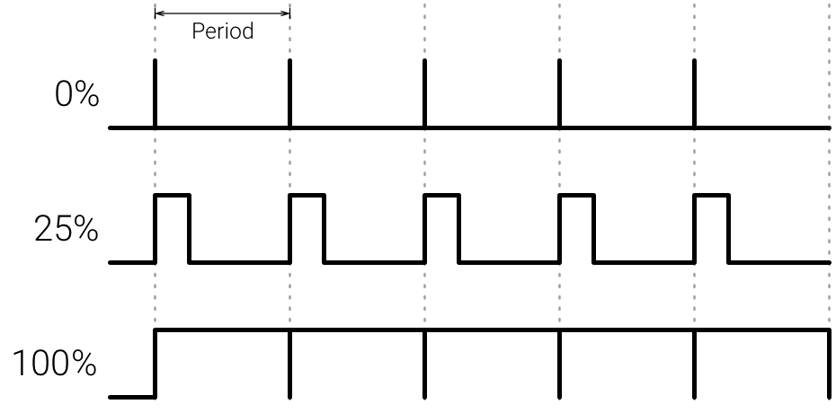
You might hope that asking the LED for either a 0% or 100% duty cycle would work well enough, but we can't guarantee how the driver operates. In the case of the WS2811 I found that a channel value of 0 results in a true 100% duty cycle (this makes sense for a common anode LED driver), but the max value (255) only approaches a 6% duty cycle.
The ability to reach a true 100% duty cycle is good for powering the sensor because it means minimal noise. The fact that the supply voltage will occasionally come up, however, is concerning because that may cause any one of the sensors to turn on and interfere with communication on the I2C bus. In order to combat this I used a low-pass RC filter that incorporates the current-limiting resistor.
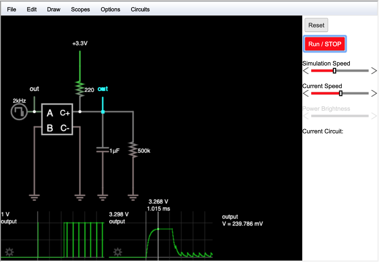
The WS2811 uses a PWM frequency of 2 kHz, so a 6% pulse would have a width of (6 / 100) • (1 / 2000) = 30 μs. A 30 μs square wave pulse contains many frequency components, the slowest of which is (1 / 30 μs) = 33.3 kHz. In order to block that frequency one would choose a corner frequency below that value. Using a simulated circuit on falstad.com/circuit, I played around with various capacitor values to get a good balance of high-frequency blocking (higher capacitor values) and the time it takes to power on a sensor (low capacitor values)
R = 220 Ω (choose a common resistor value greater than 170.37 Ω)
C = 1 μF
fc = 1 / (2 • π • 220 • 1 • 10-6) = 723 Hz
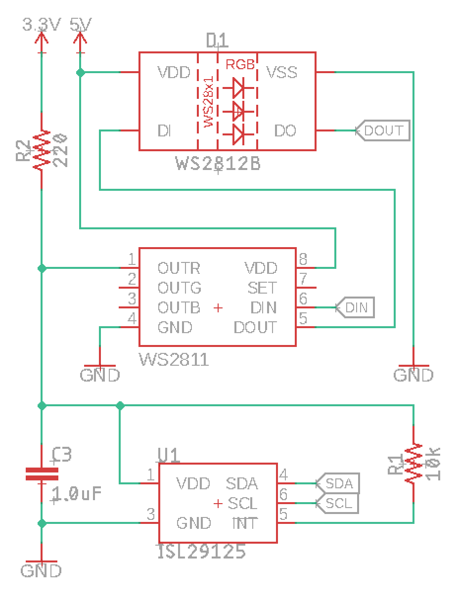
Using the design parameters from above I laid out a prototype schematic and board in Eagle.
Testing
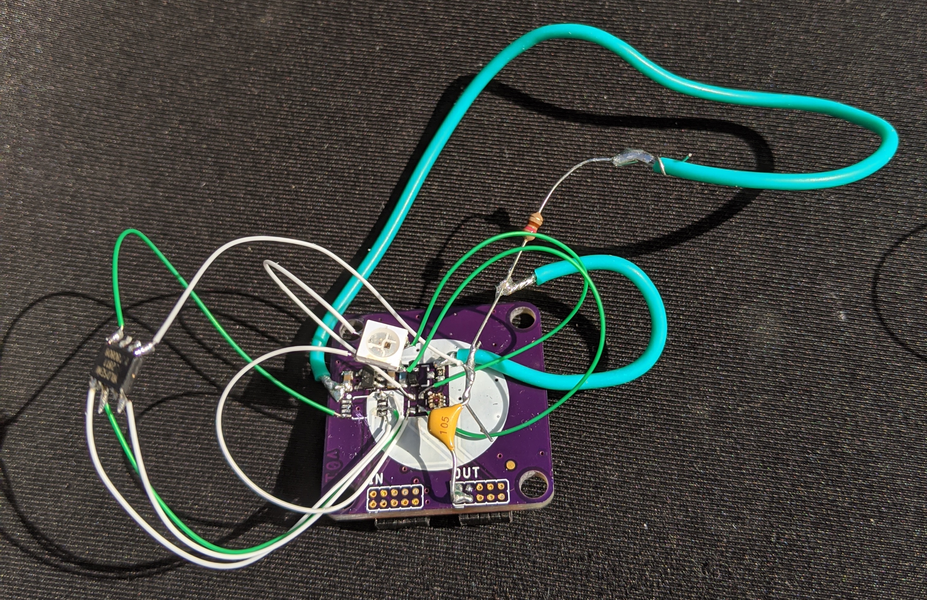
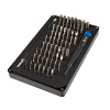
In an effort to move quickly I ordered PCBs and the WS2811 driver ICs at the same time. In fact my original design used a slightly more complicated circuit that I was able to simplify during testing. We've been discussing the simpified circuit but the boards contain a few extra components and a host of white-wire fixes. That's a lesson in why you should always do a 1:1 scale package check for any new parts that you intend on using! Below is an image of the prototype as tested:
To test the board I wrote a quick test sketch. It uses the FastLED library to control the LED data line (for the WS2811 as well as the WS2812B illumiator LED), and the SparkFun ISL29125 Arduino library to read from the RGB sensor.
/******************************************************************************
Color_Node_Test.ino

Test sketch for for turning on/off an ISL29125 RGB sensor using a WS2811 LED
driver IC.

Owen Lyke
25 Mar 2020

Requires:
SparkFun_ISL29125_Arduino_Library
FastLED library by Daniel Garcia
ESP32 based microcontroller such as the SparkFun ESP32 Thing Plus (https://www.sparkfun.com/products/15663)

Setup:
- Build your own color node based on the schematics shown at: https://www.sparkfun.com/news/3266
- Connect the I2C pins SCL and SDA to the Wire port of your ESP32 based board
- Connect the LED data line to pin 18 of the ESP32 on your board
- Connect GND and 5V lines

This code is beerware.
Distributed as-is; no warranty is given.
******************************************************************************/

/********************/
/* USER SETUP BEGIN */

#define DISPLAY_TITLES 1      // 1 to print field names to serial
#define DISPLAY_RGB 0           // 1 to print r g b values to serial
#define DISPLAY_HUE 1           // 1 to print computed h value to serial
#define DISPLAY_COLOR 1         // 1 to print nearest color to serial

// Define a type to hold detectable colors
typedef struct _color_t {
  float hue;
  const char* name;
}color_t;

// Here's the list of colors that the system can name on its own (you may add your own based on hue angle [0.0, 360] )
color_t colors[] = {
  {0.0, "Red"},
  {60.0, "Yellow"},
  {120.0, "Green"},
  {180.0, "Cyan"},
  {240.0, "Blue"},
  {300.0, "Magenta"},
};

/* USER SETUP END */
/******************/

// Includes
#include <math.h>
#include <Wire.h>
#include <FastLED.h>          // Click here to get the library: http://librarymanager/All#FastLED_Daniel_Gracia
#include "SparkFunISL29125.h" // Click here to get the library: http://librarymanager/All#SparkFun_ISl29125

// RGB sensor control
SFE_ISL29125 RGB_sensor;
unsigned int red = 0;
unsigned int green = 0;
unsigned int blue = 0;

// WS2811 / WS2812B control
#define DATA_PIN 18
#define NUM_LEDS 2    // Each color node has two 'leds' - one WS2811 to control the sensor power and one WS2812B for illumintation
CRGB leds[NUM_LEDS];

void setup() {
  Serial.begin(115200);                                     // Start Serial

  FastLED.addLeds<WS2811, DATA_PIN, RGB>(leds, NUM_LEDS);

  sensorPower(true);
  FastLED.show();
  delay(1000);

  while(!RGB_sensor.init()){                                // Initialize the ISL29125 with simple configuration so it starts sampling
    Serial.println("trying to start the sensor!");
    delay(50);
  }
  Serial.println("Sensor Initialization Successful\n\r");
}

void loop() {
  /* Begin Taking a Reading */

  sensorPower(true);                // Turn on the sensor
  setLED(200, 200, 255);            // Turn on the LED to illuminate the subject area
  FastLED.show();                   // ^- adjust the balance of white here... blue seems to need some help (higher Vf than other leds..)

  delay(2);                         // some time for sensor to come online
  RGB_sensor.init();                // now perform initialization since the sensor had been asleep

  delay(200); // sensor continuously runs ADC at ~ 10 hz so to be sure wait 0.2 seconds before reading

  delay(300); // delay to combat voltage sag from turning on all the leds...
              // I've experimentally determined that while there is no LED brightness that completely
              // eliminates noise in detected color there is a minimum total delay between turning on
              // the leds and taking a sample that gets darn close. Its approx 500 ms total (including
              // time dedicated to letting the sensor read)

              // the final product may as well turn on all the leds, wait half a second, and then sample
              // all of the color sensors rapidly.


  red = RGB_sensor.readRed();     // Sample the sensor
  green = RGB_sensor.readGreen();
  blue = RGB_sensor.readBlue();


  sensorPower(false);             // Turn off the sensor
  setLED(0, 0, 0);                // Turn off the LED
  FastLED.show();                 // Apply changes to the 'LED' data (includes WS2811 'switch' changes)

                                  // Now let's try to sample the sensor to show that it has really been shut down
  delay(1);                       // Time for the sensor VDD line to fall to 0
  RGB_sensor.init();
  RGB_sensor.readRed();
  RGB_sensor.readGreen();
  RGB_sensor.readBlue();

  printResults();                 // Show the results on the Serial monitor

  delay(200);                     // delay 200 ms before taking another reading
}

void sensorPower(bool on){
  LEDS.setBrightness(255);                                  // Ensure full brightness so that WS2811 controls are not scaled

  if(on){
    leds[0] = CRGB(0, 0, 0);                                // Turn on the sensor by writing a 0 value to the R channel
  }else{
    leds[0] = CRGB(255, 0, 0);                              // Turn off the sensor by writing 255 to the red channel
  }
}

void setLED(uint8_t R, uint8_t G, uint8_t B){
  leds[1] = CRGB(R, G, B);                                  // The LED is the second item in the 'led' array (the first is the WS2811 sensor switch)
}


/*********************/
/* UTILITY FUNCTIONS */

float max3( float Rp, float Gp, float Bp, uint8_t* index ){
  // hacky way to find maximum of three (not tested well or even well-thought-through)...
  float Cmax = 0.0;
   if(Rp >= Gp){
      if(Rp >= Bp){
        Cmax = Rp;
        *index = 0;
      }
    }
    if(Gp >= Bp){
      if(Gp >= Rp){
        Cmax = Gp;
        *index = 1;
      }
    }
    if(Bp >= Gp){
      if(Bp >= Rp){
        Cmax = Bp;
        *index = 2;
      }
    }
    return Cmax;
}

float min3( float Rp, float Gp, float Bp, uint8_t* index ){
  // hacky way to find minimum of three (not tested well or even well-thought-through)...
  float Cmin = 0.0;
   if(Rp <= Gp){
      if(Rp <= Bp){
        Cmin = Rp;
        *index = 0;
      }
    }
    if(Gp <= Bp){
      if(Gp <= Rp){
        Cmin = Gp;
        *index = 1;
      }
    }
    if(Bp <= Gp){
      if(Bp <= Rp){
        Cmin = Bp;
        *index = 2;
      }
    }
    return Cmin;
}

void printResults( void ){
    float Rp = (float)red/255;
    float Gp = (float)green/255;
    float Bp = (float)blue/255;

    uint8_t max_ind = 0;
    uint8_t min_ind = 0;
    float Cmax = max3(Rp, Gp, Bp, &max_ind);
    float Cmin = min3(Rp, Gp, Bp, &min_ind);
    float delta = Cmax - Cmin;

    float hue = 0.0;
    if(Cmax == 0.0){
      hue = 0.0;
    }else{
      switch(max_ind){
        case 0: hue = 60 * (fmod(((Gp-Bp)/delta), 6.0)); break;
        case 1: hue = 60 * (((Bp-Rp)/delta) + 2); break;
        case 2: hue = 60 * (((Rp-Gp)/delta) + 4); break;
        default: break;
      }
    }

    // search list of colors for the closest one
    //  (todo: when overall lux levels are low just say nothing is there)
    const char* identified_color = NULL;
    float prev_diff = 360.0;                              // start with a high (impossibly so) difference
    float diff = 0.0;
    uint8_t num_colors = sizeof(colors)/sizeof(color_t);
    for(uint8_t indi = 0; indi < num_colors; indi++){     // loop through all the named colors
      diff = abs(hue - colors[indi].hue);                     // find the difference between the selected color hue and the calculated hue
      if ( diff >= 180.0 ){                                   // correct for differences over 180 degrees because the spectrum is circular
        diff = 360.0 - diff;
      }
      if( diff < prev_diff ){                                 // if this difference is smaller change the detected color to this name
        prev_diff = diff;
        identified_color = colors[indi].name;
      }
    }

#if DISPLAY_RGB
#if DISPLAY_TITLES
    Serial.print("B: ");
#endif
    Serial.print(blue);
    Serial.print(" ");

#if DISPLAY_TITLES
    Serial.print("R: ");
#endif
    Serial.print(red);
    Serial.print(" ");

#if DISPLAY_TITLES
    Serial.print("G: ");
#endif
    Serial.print(green);
    Serial.print(" ");
#endif

#if DISPLAY_HUE
#if DISPLAY_TITLES
    Serial.print("Hue: ");
#endif
    Serial.print(hue);
    Serial.print(" ");
#endif

#if DISPLAY_COLOR
#if DISPLAY_TITLES
    Serial.print("Color: ");
#endif
    Serial.print(identified_color);
    Serial.print(" ");
#endif

    Serial.println();
}
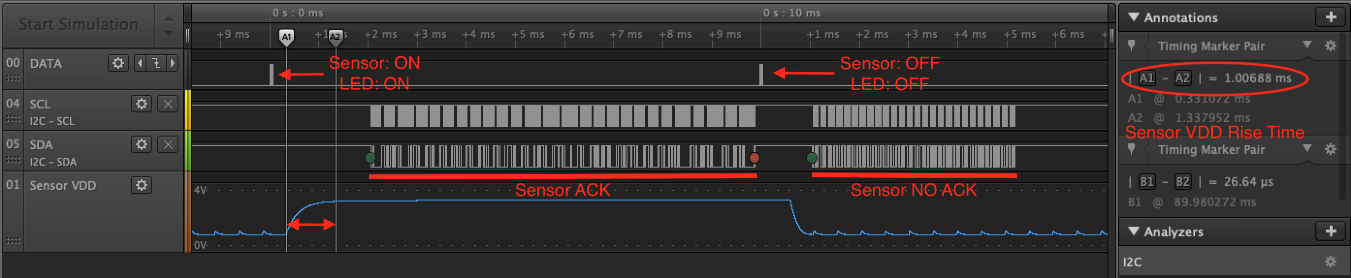
Using a digital logic analyzer I was able to record some great data. You can see that the rise time of the sensor VDD line matches what is expected from the simulation, as well as the same small ripples when the sensor is turned off. You can also see that the sensor responds to I2C transactions while it is powered. Shortly after sending the 'off' command, the VDD line falls and the sensor no longer responds to I2C transactions. This suggests that turning off unused sensors should be enough to allow using more than one sensor on the same I2C bus.
Further Considerations
This project is a work in progress. To scale this single test up to an array of 192 nodes will present more challenges such as:
- Sample speed - the test above does not leave any time for the sensor to make ADC conversions, so the readings come out as 0. In reality each sensor will need to be on for 100 to 200 ms to get a good sample.
- I2C Bus Capacitance - generally it is challenging to use I2C over long distances because of the open-drain topology.
These challenges will likely preclude the use of this method in the Rainbow Forest project. Still, using the WS2811 in creative ways could like this can be useful in a host of projects that already involve addressable LEDs such as model train layouts, DIY LED shows with special effects, and much more!
If you use the WS2811 in a project of your own let us know!
Interested in learning more about LEDs?
See our LED page for everything you need to know to start using these components in your project.


creative idea! and nice write up!!
what were your initial concept ideas for the needed sample speed?
Thanks!
The necessary sample rate is sort of dictated by the tempo of typical children's music. For example Jingle Bells, Mary Had a Lamb, and Twinkle Little Star range in BPM from 100 to 130. The staff we are designing is 4 measures of quarter notes (there is no way to specify half or whole notes other than to put multiple quarters consecutively) - or 16 beats. If we assume 120 BPM that's 2 beats per second, so the whole staff would play in 8 seconds. The specification of the staff changed a bit so there are only 7 notes to choose from at each horizontal position. That's 7 • 16 = 112 notes to sample in 8 seconds (refreshing once per play-through is what I would consider to be the bare minimum). That's 8 / 112 ~= 70 ms to sample each sensor. In terms of I2C bus speed this should be plenty of time. The problem actually lies in the operation of the ISL29125 itself. The sensor's internal ADC completes conversions at about 10 Hz. That means after initializing the sensor we need to wait at least 100 ms just to get a valid reading. When turning the sensors on and off to free up the bus it is necessary to initialize every time and suffer that 100 ms penalty.
There are a few options that I will consider moving forward. Because of the distributed nature of this installation I'm looking for a way to keep wiring to a minimum and so I'd really like to keep using this idea. One way that could be possible is if each horizontal position (group of 7 sensors) was individually controlled on their own bus. The sample rate would be increased by 16 times which would be plenty. If that fails for some reason I would fall back to a basic implementation with an I2C multiplexer - but that means a lot more wiring complexity!