
If you're in the business of creating multiple boards (like we are!) you might find that testing and programming a single board at a time can be a bit tedious. It is much easier (and faster) if you can hook up multiple boards to run your testing procedures all at once - a process called gang programming.
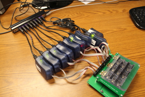
So when we started expanding production and creating many boards, our testing guru Pete Lewis set out to explore the world of gang programming. What he found was a bit discouraging - many options he found either did not exactly meet our needs or were quite expensive (like $11,000 expensive - yikes). So in classic SparkFun fashion, Pete set out to create a DIY solution.
Did he succeed? Oh yeah! Pete was able to create a fantastic system for ganged programming that we use currently in our SparkFun production process. Check out his tutorial to learn how you can do gang programming at home!


Just off topic - Seeing as Google have launched +Pages on Google+, can we please have a SparkFun one???
That's a great idea! Expect to see a SparkFun Google+ page in the next few days. In the meantime, we are on Facebook and Twitter.
Yay!!! I noticed you 'graced' Facebook and Twitter with your presence, so I thought you might do the same with G+ :-)
what do i need to do to work here? i have a spare kidney and my own oscilloscope that i could bring to work...
Your method is very common when factory gang programmers are not available. I am surprised that PCB material was used for the jig. Lasercut delrin works much better, so if you don't have a laser in house, you now need one!
Maybe they can't afford the sharks?
The pond is too shallow.
Is that an xkcd reference?
<a href="http://www.youtube.com/watch?v=Bh7bYNAHXxw">Austin Power</a> reference.
You guys are in need of a manufaturing engineer.. lol. some pneumatic fixtures will do wonders for your operation.
A Mfg. Engineer would also only use the minimum number of pogo pins to program and stabilize the chip, instead of pogos on every pin.
OR - Have the chips preloaded with the bootloader from your chip supplier (That's what we do, at the company I work at).
Pneumatic jigs sounds big, solid, and difficult to modify. We've got 10-12 weeks before a product morphs and we need a new test procedure and test jig. Pete's figured out a way to keep up with the crazy demands we put on him.
They are solid, and they are big if you've got big boards to program, but they are a lifesaver. They're also not difficult to modify. Make a standard outline and connector for your jigs, get a piece of phenolic with some placement pins, and send it down to the CNC mill to have the holes drilled in the right spots. Press in your pogo pin barrels and solder jumpers to the connector.
This is much faster than designing custom PCBs and holders for each board, having those PCBs manufactured, and assembling them. The manufacturing engineers in my department can go from a receiving a gerber file with the locations of the required test points to having a dozen production jigs manufactured in a couple days, less (a couple hours) if it was an emergency and they needed to circumvent the normal inter-departmental procedures.
I have great respect for Pete figuring this stuff out on his own, but he really needs someone who's had on-the-job experience. Sparkfun's prices could come way down if you followed industry standardized and time-proven procedures rather than blazing your own trail every step of the way.
Blazing your own trail can teach you awesome things that would never be learned if you were the same as everyone else. And besides, they haven't made a new trail "every step of the way".
I don't think so, that's the DIY spirit! hehehe
What if you used 1 STK and branched the lines out in parallel to every micro, then used some op-amps/transistors to bring every line up to normal?
I thought about that too, but that won't work because the ISP interface works bi-directionally, meaning the AVR will send data back to the PC. All the AVR's can certainly listen to the same ISP stream (it might require some buffering like you described above), but when the PC tries to read the program data back to ensure it was written to the flash properly, (this is the default recommended option) they will interfere with each other (you can't have 9 AVR's talk on one ISP bus at the same time).
Hmmm, I guess it might be possible to have a strange not-sure-if-this-is-possible circuit on the prog beds that would delay each response a certain amount of time so that each one came in individually...
Nice Write up. Curious about one thing: So you program a hex file with the bootloader and the blink sketch. Do you test to make sure all the pins work? Is that another jig or process?
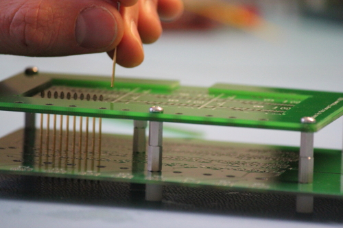
We actually don't program blink. We program another compiled hex that is written to test every IO. All the pins on the ATmega are connected to an individual pogopin. On the jig they are connected in a way that we can use some test code that pings every IO and checks for cold joints and jumpers. This is why I made the jig have a pogopin for every breakout header hole. I have been considering working on a future design that only has pogopins connected to the programming lines (to help with the pressure/hardware issues), but then we are relying solely on the AOI machine to catch any colds joints on all the other pins.
I'm confident we could test every IO for jumpers using the internal pull-up resistors and some pinging test code, but the cold joint is impossible (I think) to test without a hardware connection. The AOI is getting better and better, so this may be the direction we go. But for now, I think we'll stick with 100% hardware testing.
I'd like to throw out another suggestion, regarding the plastic clamp. Rather than hinge it, and use the spring clamps on the other side, which I can see results in uneven pressure overall, how about using some round threaded standoffs instead of the screws securing your test PCB to the lower standoffs. This will provide 4 round posts above the board. Make them long enough that 4 holes drill in the plastic clamp piece can slide over the posts. Now, mount the whole test fixture to a larger piece of wood or plastic, and use a cheap toggle clamp secured to that mounting board to clamp the plastic right in the center, to ensure even clamping pressure. You can save the pain of mounting the hinges, not have to really modify any of your existing setup, it would ensure even clamping pressure, and the toggle clamp would actually be faster--and it also has an adjustable "foot" so you can adjust the pressure to your liking. :) Just a suggestion.