Testing LEDs quickly - a new tutorial!
Test your bare LEDs with a set of hacked tweezers - and don't worry about polarity!

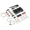
First off, let's announce the caption contest winner - Member #311485 and his caption seen below. Congrats! Check your email for information about receiving your prize (a SparkFun Inventor's Kit!).

Though it was an interesting lab experiment, the transfer of mass from car to hat turned out to have little practical value.
Now on to our post. Today we'd like to direct your attention to a new tutorial written by our testing guru Pete Lewis. Pete found a great hack to quickly and easily test LEDs using a pair of fast-switching tweezers.
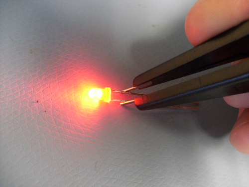
Pete used an Arduino Pro Mini, some multimeter tweezers, and a few other pieces to create a quick solution for testing out LEDs you have laying around. Is it red? Is it green? Is this the LED that I accidentally destroyed? These tweezers make answering these questions easy. Here is the wish list with the parts you'll need to build your own:
Check out the full tutorial to see how to put together a pair of your own. Happy hacking!
Interested in learning more about LEDs?
See our LED page for everything you need to know to start using these components in your project.


seriously ... that caption won?
The humor committee has spoken. Yep!
Please replace your humor board.
Please replace your humor board.
The humor board is obviously not 100%e-tested. There's certainly a cold soldered joint or a short somewhere.
Lol
Man, tough crowd.
No kidding. Sure it's overkill, but who cares? That's part of the fun of something like the pro mini. If someone wants to show the circuit for a PNP/NPN setup, I'd enjoy seeing it also-but don't knock on someone else's sense of fun.
edit: On a side note, interesting that I can down-vote my own comment. :)
Maybe off topic, but given how you can find surplus LED's cheap, here's a fun little game I used to play with other geek friends. Take two LEDs, and a slot car race set--remove the cars. Now, put one LED in the slot for one car, a second in the slot for the second car--make sure that the polarity in the tracks is such that the LED' are forward biased. Now, using the slot car controllers, the goal is to see who cam make their LED light the brightest the longest before it burns out or explodes. :) It can be suprisingly tricky to accomplish. Safety glasses and fire extiguisher reccomended :D
Aww... I liked "Hatters gonna hat"...
Geez guys, your missing the entire point of this tutorial! It is to get you to buy stuff you don't really need, and to generate sales on parts that are probably not the fastest moving.
What the... why can't I just solder the battery holder to the tweezers? I would save... $37.23.
For PTH LEDs, why even use tweezers or indeed leads at all? A coin/button cell (2016, 2032, etc.) will do the job. But that's not the point :)
You probably could. But Pete wanted to make it have a bit more functionality - the code toggles the 'tweezer lines' and also controls an alarm that lets you know if you leave the tweezers turned on.
Not to detract from this neat little project, I would actually like to see a project with similar functionality, without using a micro. I think a lot of younger people who use micros for everything, and people like me who started as programmers, are lacking in one fundamental area of knowledge, Electronics.
Yeah but, all of that could have been done with another $1 of parts... -- and normally -- I'm all for throwing micro-controllers at things -- it's fun -- but he didn't do that either, did he? He through an Arduino at it. If he was dead set on using a micro, he could have at least used an ATTiny and not been so wasteful -- heck it would have fit on the body of the tweezers making a compact and elegant part.
Also, he does loose a bit of functionality here versus the coin cell -- in that, if the leads are clipped on the LED, he'll never know which one is positive.
Why on earth is a microcontroller required to light up an led? Surely just the tweezers and a battery is enough.
Or... just a watch battery. I mean quickly is definitely a lie here -- because you're never going to have all of those things where and when you need them -- instead if you just have watch batteries floating around in your various kits, you'll always have one handy and wham, there it goes.
At the worst if they wanted to make fancy tweezers that ran the LED in both directions (alternating), they could just build an astable-multivibrator circuit (2 transistors, a couple caps and resistors) and then you have the polarity issue solved.
It is 'enough' - but read the actual Tutorial. The point is that the microcontroller switches the polarity so that it doesn't matter which way around you have the tweezers hooked up to the LED. Granted, this could be done with a simpler circuit - but then some other potential perks would be lost. Read also my slightly rant-y comment above.
You could do it with a 555, and a pair of PNP and NPN transistors to reverse the polarity.
Could do it without the 555 - just 2 resistors (4 if you want to limit current through the LEDs), 2 capacitors and 2 NPN or PNP transistors. But there's more potential use through the microcontroller that goes untapped in the tutorial.
This looked like a fun little project. I breadboarded it with an ATTINY85 using all 5 pins, 2 1 ohm resistors, and an indicator LED and used it with my homemade tweezers. The LED under test lights either way around as in the posted project but the indicator LED also lights if the positive terminal of the tweezers is on the positive side of the LED under test.
From here it would be easy to add code to latch the uC pins the right way around until the LED is removed from test and then revert back to normal mode when the LED is removed.
Going beyond that you could put the uC to sleep and wake it with hardware interrupts on the analog pins used to sense polarity and you wouldn't need a power switch. The SOIC-8 chip, a couple of surface mount resistors, a surface mount led, and a small 3V button cell and it should all mount on the tweezers and run for a long time without a power switch. The circuit could easily be etched right onto the tweezers if making them from scratch and you would likely need only one small jumper wire to connect to the opposite arm. The entire end could then be covered in shrink wrap.
Hmmm . . . maybe I should finish it up and post an instructable.
Wow, you guys are tough on the tweezers. I actually thought it was a cool tutorial! Personally, I would add a few more features, like a continuity tester (using the buzzer).
These tweezers seem more like a solution in search of a problem.
It must be nice having the luxury of a free stockroom, so you can throw nearly $40 worth of hardware at a problem that a $0.50 battery already solves.
A few points: as nice as that sounds, we don't just eat straight out of the candy bin. To keep inventory numbers correct (and keep from going out of business), we all have to put in (and justify) an order for everything we use. We are our own customers.
Also, seconds saved add up in this business. Way too often we find ourselves in situations where e.g. a supplier sent us 1000 each of 4 colors of water-clear LEDs, but -all in one bag-. For the employee who lost rock-paper-scissors and has to sort these things, making it as fast and easy as possible often justifies spending more money to make a great tool to do so.
Any project which includes an Arduino Pro Mini and an FTDI breakout would be more straightforward and less expensive on a Teensy. Just Saying. Teensy - everything Arduino should have been from day 1.
I would just do it with a bare AVR microcontroller (or the microcontroller flavor of your choice) and a few extra components. Probably a $10 project, at most (excluding the FTDI for programming, of course).
Don't even use an FTDI. This project doesn't need UART, so don't pay for a chip that has it.
I meant to program the bare AVR.
Hmmm... I guess so. I always just use a coin cell.
I have made one that is not only smaller and cheaper, it is more efficient and can be made from on hand parts. Do you want to see pictures?
I see one issue with the code. The tweezers stay in one state a lot longer than they do in the other. As a result if you have the tweezers connected one the LED will light brighter than the other way (you might not even see the led light at all unless you reverse the connection). The code sets the tweezers to one polarity at the top of the code, then switches it back at once. It then goes through a test of the timer, and returns to the main loop before getting back to the top of the loop() function. There could be a 2:1 or 3:1 time difference between on states. You might want to put a few nops' in the middle of the polarity switch to even things out.
I guess everything is called a hack these days.
In my mind, repurposing something (like these multimeter tweezers) to do something they weren't intended for is definitely a hack. But...I could be wrong! How would you define "hacking" or "a hack?"
Personally, I would classify this as a build. Yes this is not a usual use of these probes, but it is not a far fetched idea. The probes are used in testing. I personally use my multimeters diode test to check the LED polarity and such. In addition, there is no reverse engineering used. That is usually my definition of a hack. A re purposing of already available products or tools. Some could argue that this is a repurpose, but I feel like it just didn't reach that mark of a true hack. On a side note, the build is vastly overdone. A simple pic10f200 or an ATTiny on a breadboard could have achieved the same. I could see doing this for... $10? If that?
While I can't comment on what defines 'a hack' (unless applying it to myself), isn't using tweezers - or just two test leads - with a multimeter set to diode testing mode standard fare for testing an LED for: 1. whether it works or not
what color it is, in case it's not obvious (clear body)
what current it might enjoy best (a very iffy approach)
In that way, it's probably not really a 'hack'.
Now, I understand that part of the point of what makes this special (and may be its claim to 'hack' status) is that it reverses polarity so that it doesn't matter whether you have the anode and cathode hooked up correctly.
On the other hand, this leads to:
Inability to the polarity of LEDs that have no clear polarity indication (some SMD LEDs)*
Inability to test LEDs that require a correct polarity to work correctly (anything from simple blinking LEDs to 2-lead RGB LEDs with built-in programming)**
Inability to correctly test LEDs that are bipolar (red one way, green another, say)
Inability to test LEDs that are not actually LEDs but rather e.g. photodiodes
'* Although it should be possible to program the pro mini to use its LED or the buzzer to indicate polarity - as long you remember LED state/buzzer tone / lead correlation.
'* * Dependent on LED characteristic. If you switch fast enough, internal caps just might be enough. On the other hand, the reversed polarity just might throw a spanner into the works. But odds are that you should be able to detect the correct polarity, stop switching altogether, and keep it in the current state. If both ways seem to work, switch to a slower frequency (say 0.5Hz) to deal with the bipolars.
It's still cool enough that for most things it really would be a useful tool for people working with LEDs a lot, and would be even more useful with the polarity indication and polarity-hold options. Perhaps it could be 'hacked' on?