Credit Card Skimmers Evolved: Shimming
Detectives came knocking again, and this time they brought a new toy!

You may remember last year when we were approached by law enforcement to help them investigate some credit card skimmers that were removed from gas pumps in the Denver area. If you haven't read it yet, check out Nate's excellent article all about that experience! That investigation led us to develop the Skimmer Scanner App, allowing Bluetooth-capable Android phones to detect the presence of skimmers like the ones we reverse engineered.
Earlier this year, the detectives came back and this time they had a new device for use to check out: A credit card shimmer.
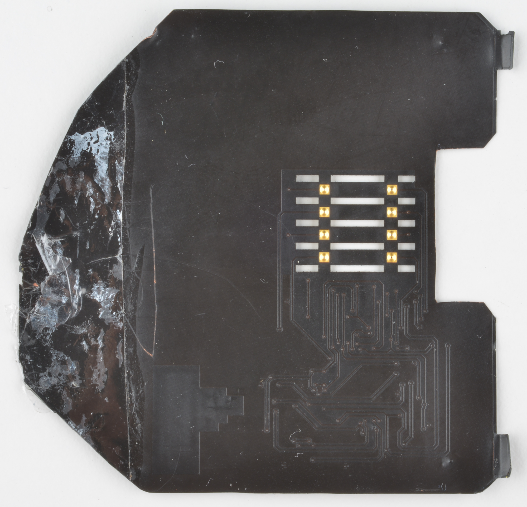
This device is designed to glue into the top inside of a chip enabled credit card reader and skim credit card information through the EMV chip. The advantage to this method is twofold: Firstly, the gas pump doesn't need to be opened in order to install it. Secondly, it's nearly undetectable, even during routine maintenance.
To make the device thin enough to insert into the card reader without mechanical interference, it's built on a polyimide film flexible PCB. These are getting surprisingly inexpensive these days and I'll touch on that again later in the post. First, let's dig into this thing and see if we can figure out how it's put together...
Reverse Engineering for Kids Who Skipped Class
When you're faced with a new hardware device, sometimes it's hard to know where to start. I've put together a handful of steps that always help me to get started investigating an embedded device. They won't get you all the way through a reverse engineering job, but they'll usually get you on the right track:
Look for numbers and Google them
Most of the components that you encounter will have a part number or — in the case of very small parts — a 3 or 4 digit "marking code". In the case of part numbers, simply plugging them into Google will usually yield a datasheet without too much effort. You'll very quickly form a love/hate relationship with sites like ALLDATASHEET.COM which will often claim to have the datasheet for a part even if they don't. In the case of marking codes on smaller parts — being only 3 or 4 digits long — you'll find that there is a lot of overlap between different devices from different manufacturers. It can be helpful to visually identify the package type (e.g. SOT23) and search that along with the marking code. Marking codes are usually included in datasheets, even in summary sheets, within a table of available package types for a given device. You may need to take note of multiple possible matches and narrow it down later using context clues from the circuit design.
Find out how it talks so you can listen to it
Step one should have identified a few parts that talk to the outside world; Anything with a radio, a UART/USI, a programming port, or similar will be of interest during this step. Make yourself a list of these features and collect whatever you'll need to listen in: oscilloscopes, logic analyzers, and usb-serial bridges are all helpful here.
Power it up (carefully) and see if it talks
Now we get to actually power up the board, but whenever you apply power to an unknown device you should take some precautions. First of all, double and triple check the datasheets for all of your identified components to make sure you're not about to exceed the maximum specs on anything. Second, skim the board for voltage regulators, current limiting resistors, protection diodes, etc. Finally, power the board using a current limiting supply so that just in case something does go wrong, the board can't suck down a few amps and self-destruct.
Hook up your diagnostic tools, flip on the power and cross your fingers for signs of life. During this step you might notice things like a discrete EEPROM being unlocked or a radio module being initialized. If you're super lucky, you might even get a debug menu over the serial port... if you're, like, super lucky.
Start asking it questions
Assuming you were able to open a channel of communication — maybe a serial debug port or a radio connection — your next step should be to throw some junk at it. Slam some plus signs and dollar signs into the terminal and see if you get a response. If it starts talking then you've got your foot in the door, if it doesn't start talking then maybe you need to try step 5.
Make the device feel at home
If the device you're targeting is designed to be part of a larger system, try to emulate the environment of that larger system. You might not be able to buy, say, an ATM just for testing but it's pretty easy to get hold of a replacement card reader for an ATM.
Okay, For Real This Time...
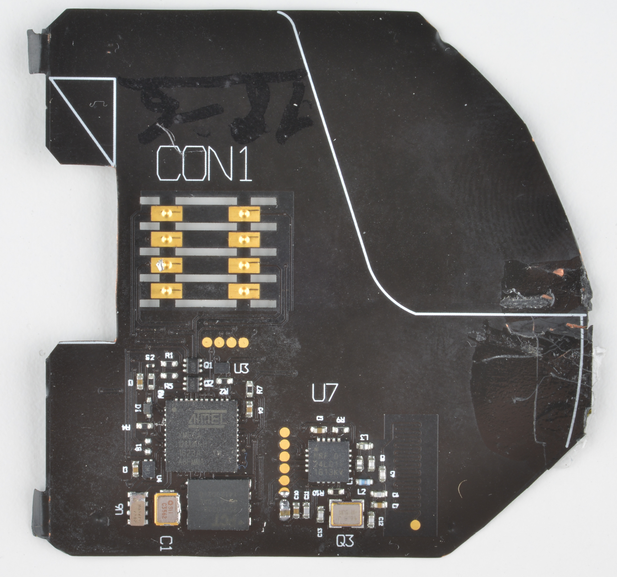
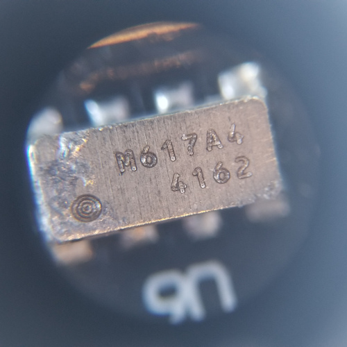
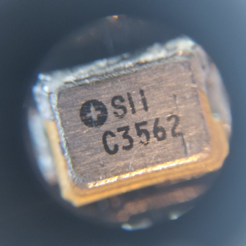
Now that we've gone through the steps, let's see how well they applied to my investigation of the credit card shimmer. Step 1, of course, was to find some part numbers so I dug my microscope out of the tool pile and took a bunch of snapshots so I wouldn't be constantly squinting at this thing. Here are the pics I used for reference while I was Googling around:
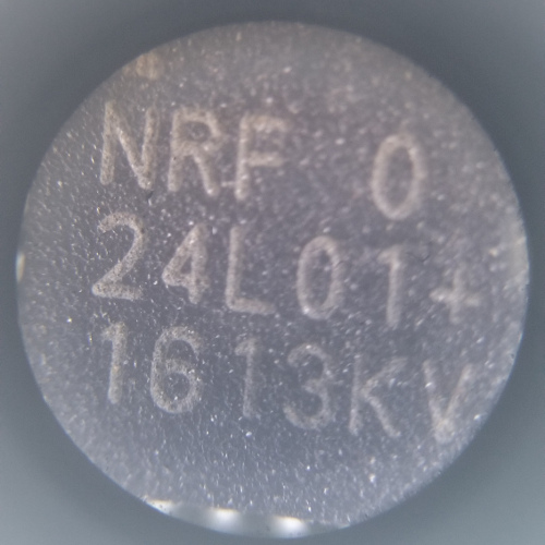
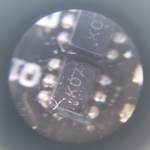
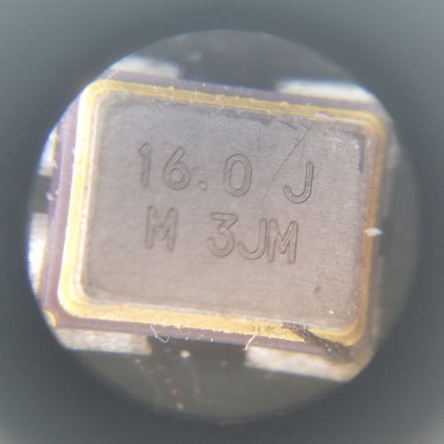

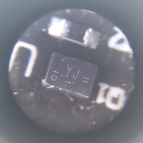
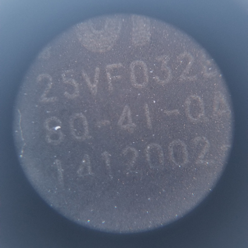
...and the Google tree hath yielded fruit! I managed to find the following parts resources:
Some of these were harder to hunt down than others. For instance, this dual PNP transistor is available in the same package with the same marking code as the Nexperia analog mux/demux listed above. The only way to tell which was which was to look at the surrounding circuit and try to work out which made the most sense. I'm still not sure I have it right, to be honest. The RTC was another part that was incredibly difficult to hunt down. At first it looked like some kind of crystal, but it appeared to be connected to a crystal (the "crystal" in question turned out to be the SII supercapacitor) so that didn't make sense. It wasn't until I traced it back to the I²C pins on the ATmega that I was able to work it out.
While skimming these datasheets, I made a little list of possible trailheads where I might start signal probing. Obviously the ATmega has a few serial interfaces, including a programming interface that's broken out to testpoints on the board. Two of those interfaces are connected to other devices on the board: the SPI bus connects to both the flash memory and the radio, the I²C bus services the RTC. Those will be worth looking at on the logic analyzer. There's also the radio itself, which we already have a breakout board for, so we'll definitely be listening to that. Finally, of course, there's the EMV chip contacts themselves which are connected to various GPIO on the ATmega.
- Programming Header - This turned out to be a dead end. Connecting to a programmer revealed that the fuse bits were blown and the firmware was locked in, no hex dumps for me.
- Radio - There did appear to be traffic on the SPI bus for the radio, but it was just initialization code. Attempting to send or receive data using a paired radio yielded complete radio silence.
- Flash Memory - An attempt to dump the contents of the Flash memory chip was greeted with what appeared to be garbage (or possibly encrypted data) and not very much of it.
- EMV Chip Contacts - It seemed likely that these pads were waiting for some kind of valid input from the gas pump card reader. There wasn't any activity on these pads after simply powering up the shimmer.
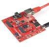
So that's four strikes, which doesn't bode well for step four. So we'll skip to step five and see if we can make it feel more at home. We acquired an EMV capable card reader with an RS-232 interface. My theory was that even without initiating a payment, the card reader would at least provide power and clock timing that the ATmega relied on. To try to see what was going on, however, I would need to get in between the reader and the shimmer... and because each side of the shimmer's EMV pad are isolated from eachother, it would also help to get in between the shimmer and a target card. To accomplish this task, I design Shim-Shim. He's a shim that shim's the shim:
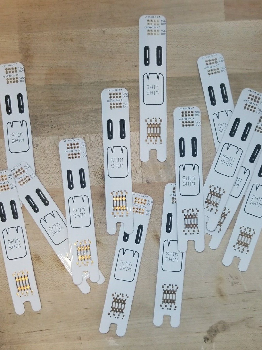
Shim-Shim breaks out the EMV shim pattern from the shimmer to two separate groups of 0.1" headers, one for the top side and one for the bottom side. These headers made it easier to connect the test probes from my Saleae logic analyzer. I had them made on polyimide film by PCBWay and it only cost me about 80 USD for 10 of them — which was really more like 15 because I guess they threw a few extra on the panel. Being about 4¼ in² and 2-layer, these would have cost me $80 per piece just a few years ago. Anyway, this is what the test fixture looked like:
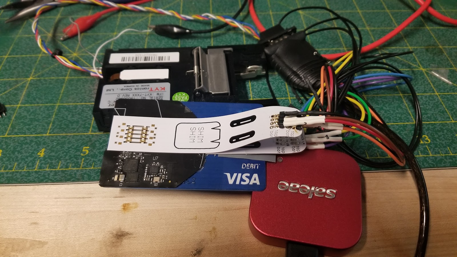
With a little effort, the entire stack of devices could be inserted into the card reader alongside the target card (read: my debit card) and I made several recordings this way using the logic analyzer. I was able to see the card reader applying a reset signal and then a clock signal but neither my card or the shimmer would ACK. In fact, probing other portions of the shimmer, I was no longer able to find any signs of life. It may very well be that — with all of my fooling around — I managed to brick it. So what do we do now? Well... we can at least find out what the hardware is capable of.
Tracing Traces
We weren't able to learn much from my usual strategies so I moved on to generating a schematic. My method for doing this was to start from high resolution photos of each side of the board. Since this board has only 2 layers, it's easy enough to see where all of the traces go, aside from where they run under parts. I imported these photos into InkScape, a vector illustration tool, and started drawing lines over all of the traces, using yellow for the top traces and green for the bottom traces.
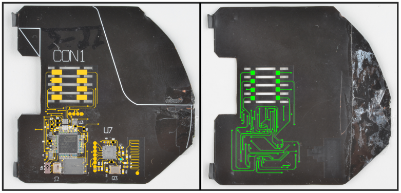
After that was finished, I was able to mirror the bottom layer and underlay it with the top layer to trace the vias. Once I had a unified sketch of all the traces, I labeled the different signal nets using different colors. When I ran out of easily distinguished colors, I'd make a copy of the drawing with those nets removed and start using colors over again.
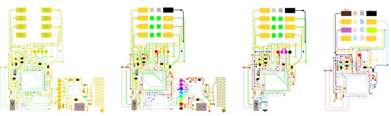
This helped me break down each subsystem of the board and make note of them in EAGLE. Finally, I flattened all of the different nets into one image. That process yielded something that looks kind of like a subway map:
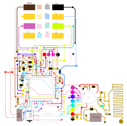
As you may be able to see, I captured the pin assignment diagrams from the datasheets of each part and aligned it with that part's position in the circuit. This made it very easy to see, for instance, which traces may be the SPI bus or the GND bus or VCC. As I went along, I was copying the nets into EAGLE and making symbols for any parts that needed them. In the end — and after some verification with an ohmmeter and subsequent revision — I was left with a comprehensive circuit schematic for the shimmer:
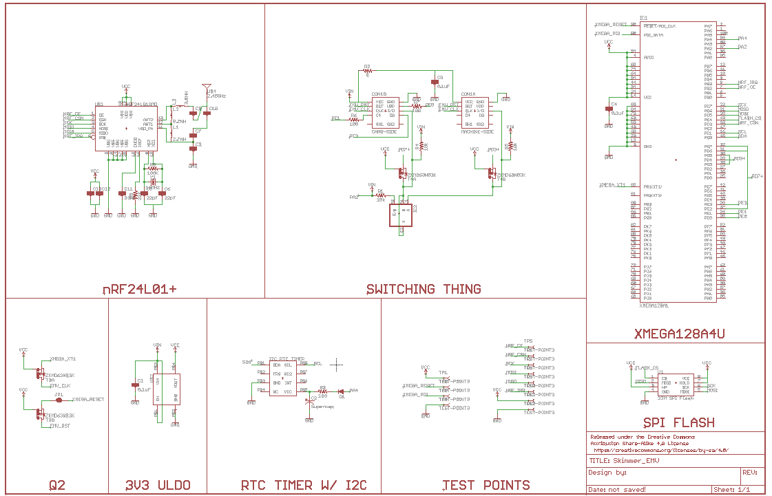
As you may be able to tell from the schematic, simply identifying a component isn't always sufficient for determining its use. For instance, the subsystem labeled "Switching Thing" appears to be for switching the GPIO connections to the two sets of EMV pads. It may allow the shimmer to switch between man-in-the-middle mode and some kind of pass-thru mode.
So What Did We Learn Here?
I've now pretty much told you everything that I know about the device. We may know what it's capable of doing, but we don't know exactly what it is doing. Honestly, this investigation has turned up more questions than answers so far:
Is the radio module being used to periodically exfiltrate stored CC#s to a receiver device or is it being used to relay transaction tokens straight to an internet connected receiver installed nearby?
Is the skimmer listening passively to the transaction and recording it or is it just using the card reader for power to conduct a separate interaction with the target card before acting as a pass-thru?
One thing that we learned, as SparkX, was that Micro Crystal Switzerland makes some very cool RTCs. In fact, the discovery of that device and the accompanying supercapacitor was the inspiration for this breakout board:
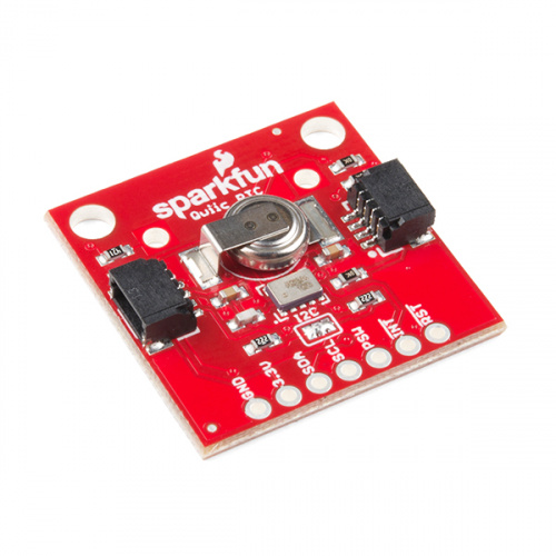
You'll notice that the RTC itself is from the same product line. If it's good enough for skimmers, it's good enough for us. Whoever was laying out the shimmer circuit knew what they were doing.
This project was a lot of fun even though I never was able to find out exactly how the attack works. I'm still crossing my fingers that the detectives find another one of these devices and that they'll uncover a nearby internet gateway for the nRF24L01+ radio. Until then, there's not much I can do. Hopefully, you enjoyed reading about my attempt at understanding this thing and with any luck you picked up some useful pointers. If you have any ideas for tests I should do or some method that you think I should try to make this thing twitch, I'd love to hear it in the comments.
Happy Hacking!
This article was adapted from a talk that I gave at SXSW Interactive 2018. You can listen to a recording of that session here!


Hey Nick I am really impressed of your work ,.can you send me the Gerber file , or the eagle file I will continue your invigatation to the bottom of it , and will tell you the results.
FYI... what I'd do is to listen to nrf traffic for some sort of password before sending out the data dump. that makes it impossible to passively detect this device and impractible to do it actively (you don't know the pw.)
I wonder if the police can reach out to some board manufacturers with the PCB layout or partial schematic to find out if they manufactured it and who they sent it to if so. Or maybe the manufacturer or reseller of one of the specialty components. It may not be enough for a no-knock warrant, but could be used to corroborate or to narrow down the list of suspects. This is high-tech enough the carder didn't make it from scratch in his basement out of parts on-hand..
If you're in the credit card stealing game, no reason you shouldn't have a list of stolen cards to use to place orders with parts distributors to avoid trace ability.
Are there any plans to update your skimmer app? A lot has happened in the 2 years since you've released it. Thanks!
You gave the link to listen, but I could find nowhere on that page to actually listen. It just gave info on the talk but no link to listen. I registered and still no link was given.
So how can we listen to that talk?
I was able to hit the play button under the large image on the link to get it to play.
The Pi 3+ Wifi was recently hacked and turned into an SDR. I think this would be a fitting application to try and capture the radios in the wild.
https://www.rtl-sdr.com/nexmon-sdr-using-the-wifi-chip-on-a-raspberry-pi-3b-as-a-tx-capable-sdr/
https://github.com/seemoo-lab/mobisys2018_nexmon_software_defined_radio
https://hackaday.com/2014/08/05/sniffing-nrf24l01-traffic-with-wireshark/
People getting away from Bluetooth as it is too easy to detect with OSH...