Enginursday: Boulder Bounces
A re-creation of our Simon Says Soldering Kit using trampolines, spot lights and a ton of new sounds!

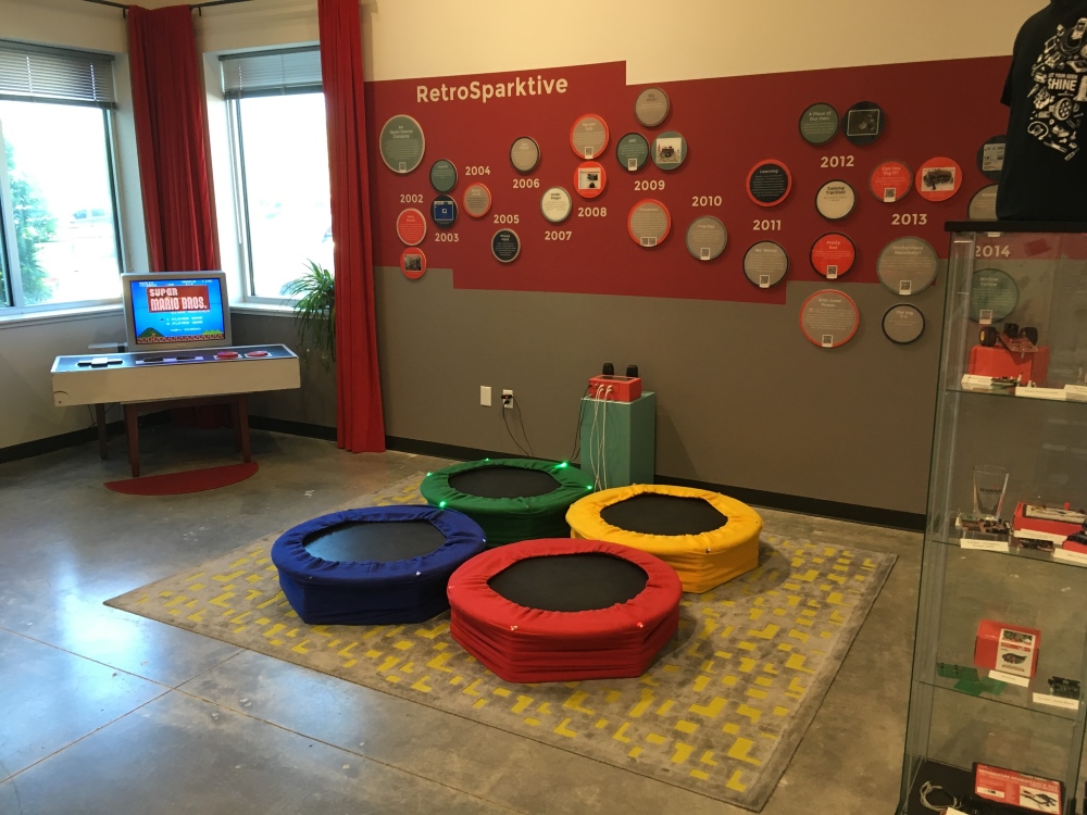
SparkFun recently teamed up with the Museum of Boulder to create a new exhibit called Boulder Bounces. It’s a re-creation of our Simon Says Soldering Kit, but using trampolines instead of buttons, and spotlights instead of LEDs.
The purpose of Boulder Bounces is to augment another exhibit called Sportsology, which has interactive areas where people can learn about their own agility and test their strength doing various sports activities. The museum wanted to add something geared toward toddlers to this area.

Digital mock up from the project proposal
Emily Zinn, their curator of education, had been to SparkFun for a collaboration involving their new makerspace, saw the original Simon Says trampolines and thought they would be the perfect addition!
The original Simon trampolines - currently located at SparkFun
Amazingly, the original trampolines have survived almost five years since their original Dunk Tank Hack Installation – they have even been on tour across the nation a couple times! They require very little maintenance (mostly cracking wires and LEDs), but I was very excited to create them a second time and improve on the original version.
Lots of improvements
Control panel with new gameplay modes
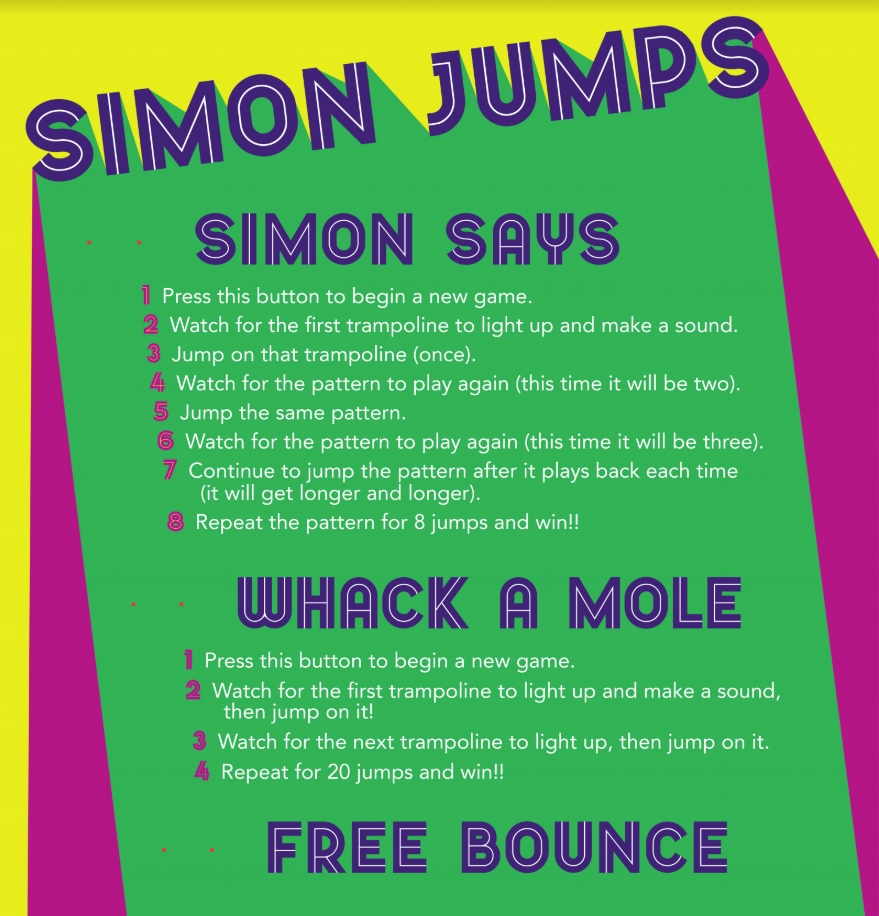
We're most excited about the addition of two new gameplay modes: "Free Bounce" and "Whack A Mole."
Free Bounce simply lets you jump for fun. You hear a sound and the spotlight fires each time you jump. If there is no jumping for 30 seconds, the exhibit will default into this mode.
Whack a mole is a bit more challenging. It plays just like the old carnival game; when you see a trampoline light up, you jump on it.
If you want to really test your memorization and jumping skills, then you can try Simon Says and memorize up to eight jumps to win!
Another major upgrade was the elimination of the center gap in the trampolines. I have always dreamed of welding a single frame for all of them, but with only three weeks to get this project completed, there simply wasn't enough time. We found some hexagonal trampolines that fit together quite nicely instead.
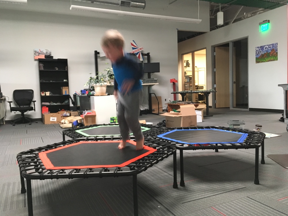
Hexagonal trampolines with no center gap
As with any slight change to a design, this added complexity elsewhere. The custom covers became quite a challenge, but they sure came out looking awesome!
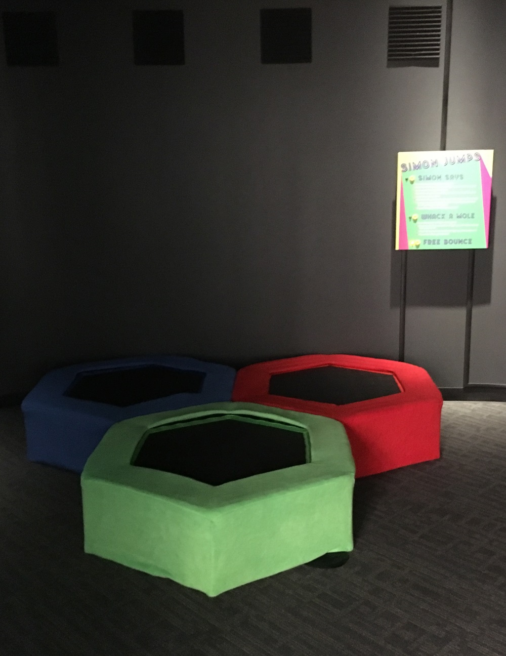
Custom hexagonal covers
The original installation used exercise trampolines that came with a very handy triggering switch.
Version 1 mechanical switch
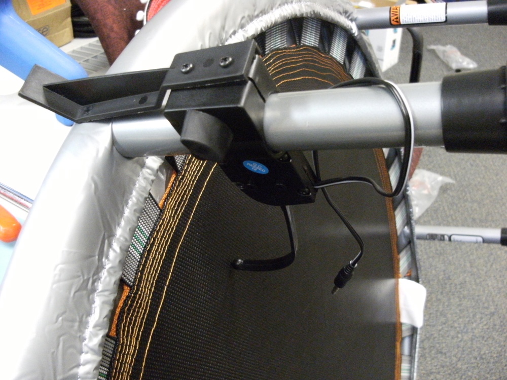
These mechanical momentary switches work really well for most jumpers. However, some of the really lightweight jumpers didn't cause enough movement to close the switch, and so the occasional jump was missed. To solve this, we switched to a more analog sensing approach, and used the Ultrasonic Sensor.
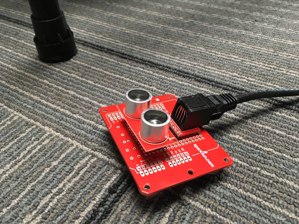
Version 2 used Ultrasonic Rangefinders
This allowed for a more precise measurement of the trampoline skin and we could sense even the slightest of movements – no toddler's jump missed!
The original version involved a lot of hand soldering of wires. A lot of the connections were made directly to the ATMega328 pins on the Simon Says PCB:
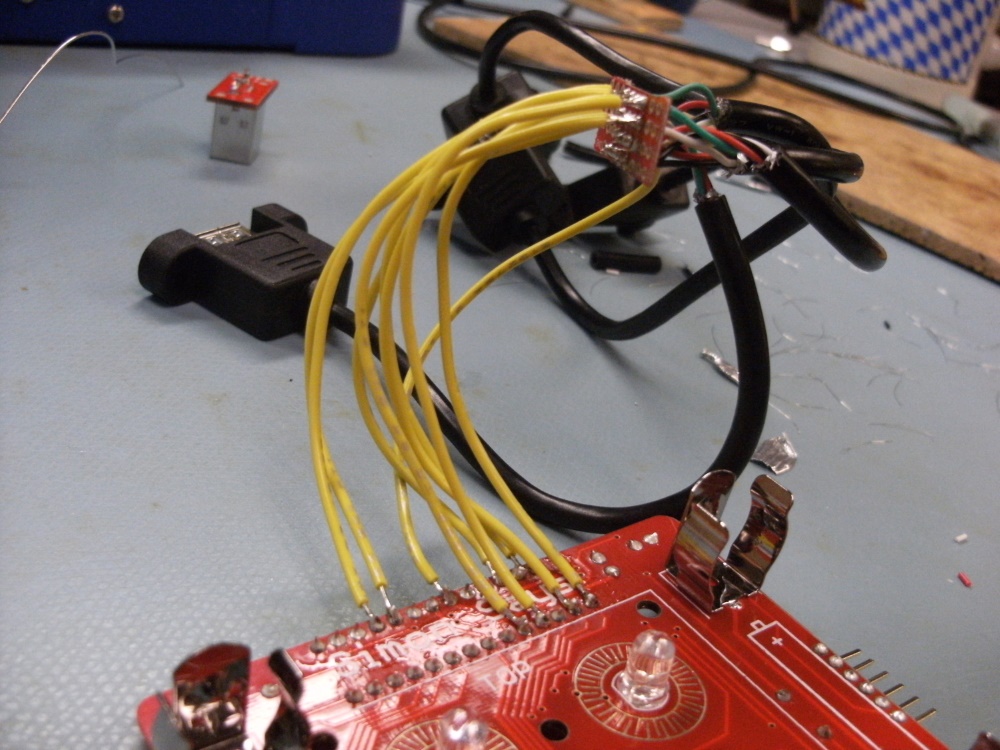
Lots of hand wiring - wait, which ADC did I wire up?
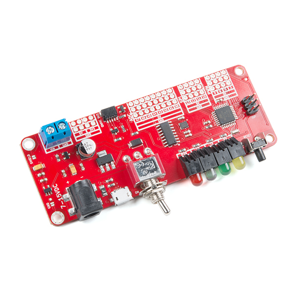
For this new version, I designed a custom PCB to keep things organized.
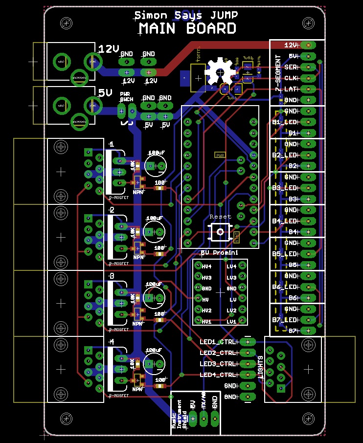
Custom PCB design
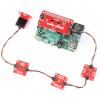
I've had a couple requests from educators for assistance re-creating their own Simon trampolines installation, so I approached this next version with that in mind. I tried to keep it easy to re-create with less point-to-point hand soldering, so it was a little more accessible for a classroom with little soldering or coding experience. I also opted to use a Arduino Pro Mini to keep things easy to replace.
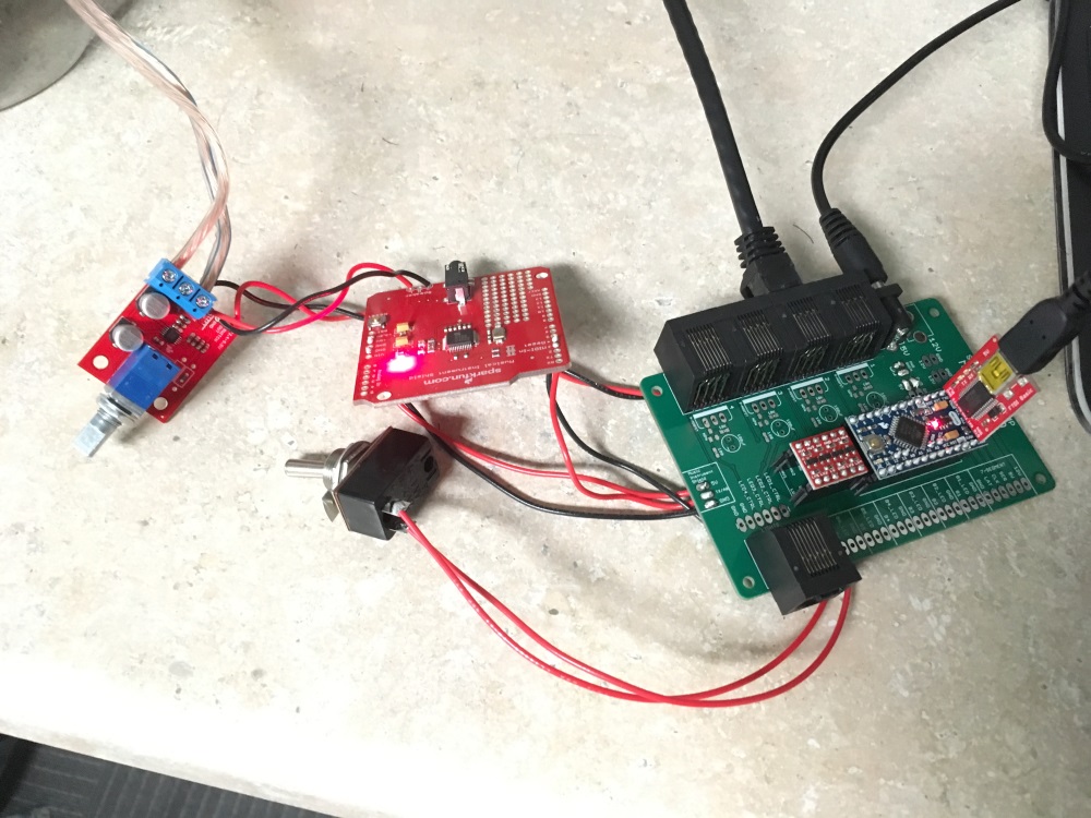
Some parts wired up during initial development
The ethernet cables (and connectors) also helped cut down on hand wiring connections, but with the addition of the control panels, there was still plenty of soldering to do:
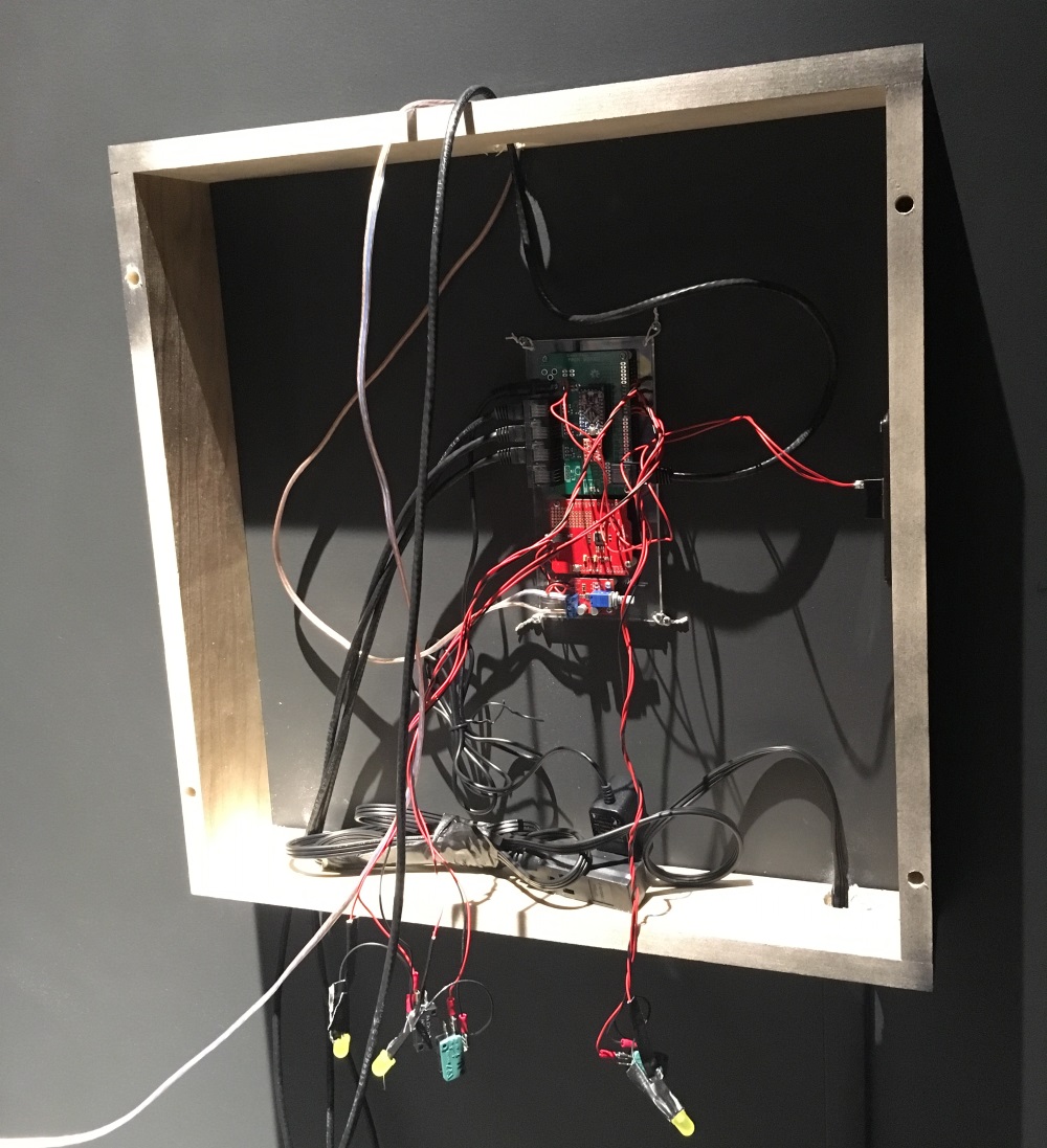
The inside of the main control panel
The second version also included two more trampolines for the toddlers: "Mighty Mini" and "Hop and Hear." They both include more sophisticated sounds and the Mighty Mini has a counting feature!
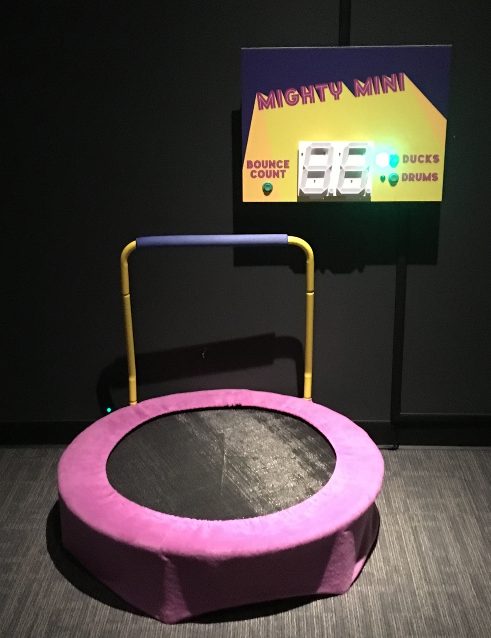
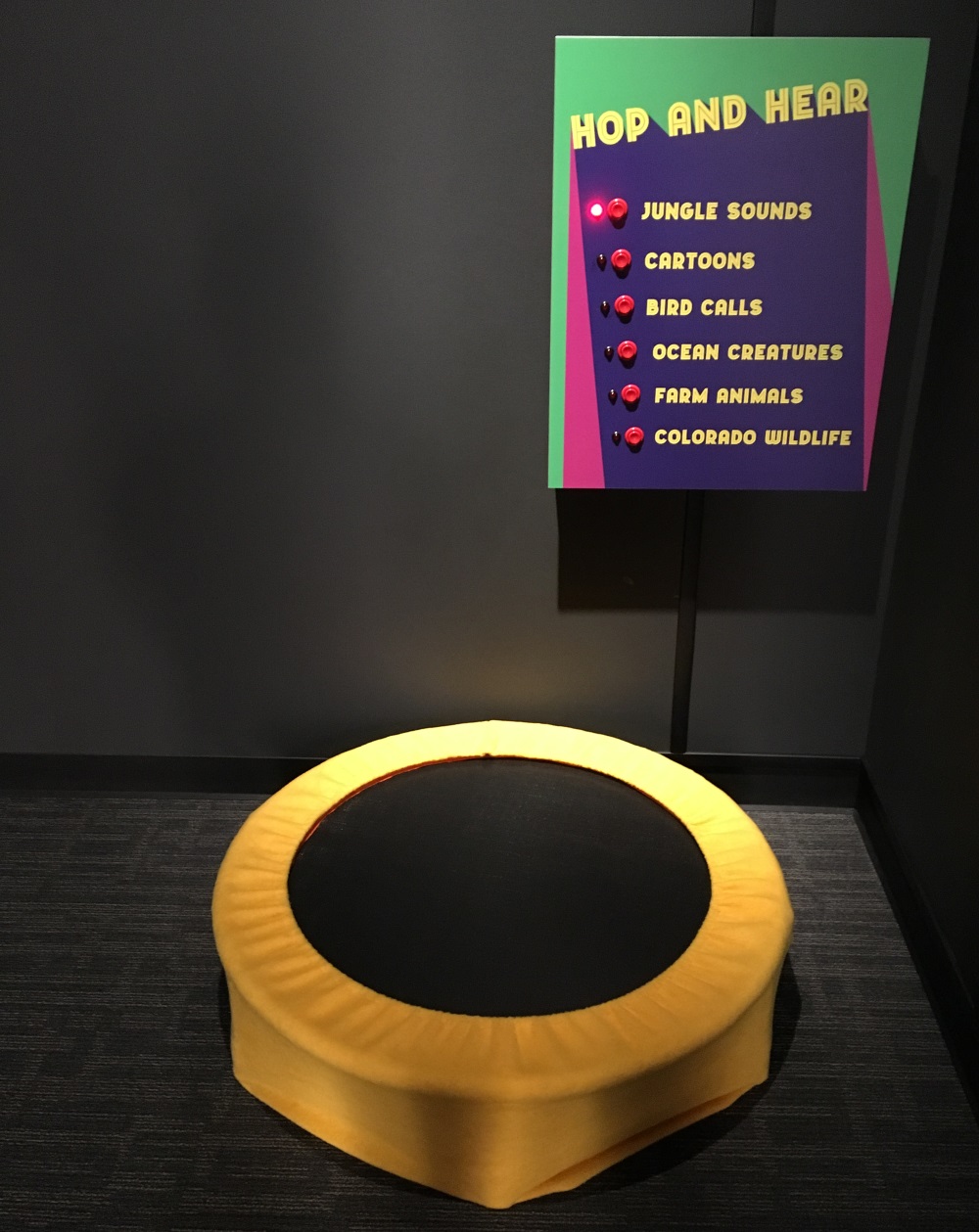
Two additional trampolines
Design Challenges
One of the most challenging parts of this project, by far, was the fact that we only had three weeks to get it up and running. We underestimated the time needed for most of the installation steps, and did not add in enough buffer for any surprise problems. Bringing in new design techniques (hexagon shapes) and using new technologies (ultrasonic sensors, Tsunami sound boards) added some surprise extra development work that compounded the time crunch.
The first surprise came from the ultrasonic range sensors. I did some testing with two sensors on the old Simon Says installation, so I naively assumed this would be easy. I was able to get good readings from two sensors sequentially, but I didn't do any testing with two trampolines being jumped on at the exact same time. I later found that when you have two rangefinders in close proximity shooting up at angled surfaces, there can be some really strange readings. The "send" signal from one sensor can incorrectly "echo" its way to the next sensor and cause errors. Ultimately, I was able to tweak the timing of the sequential readings and also filter out some of the erroneous data, but this extra troubleshooting added an extra 4-5 hours of work!
The second surprise came from the Tsunami Super Wav Trigger. I was experiencing some strange behavior - the Tsunami's boards seemed to be missing triggers, making strange buzzing sounds and eventually crashing. After spending a day and a half troubleshooting, I eventually found that one of my uSD card settings was causing the issue - I had my file allocation size set incorrectly to four kilobytes. After I switched it to 32 kilobytes, my Tsunami boards worked flawlessly.
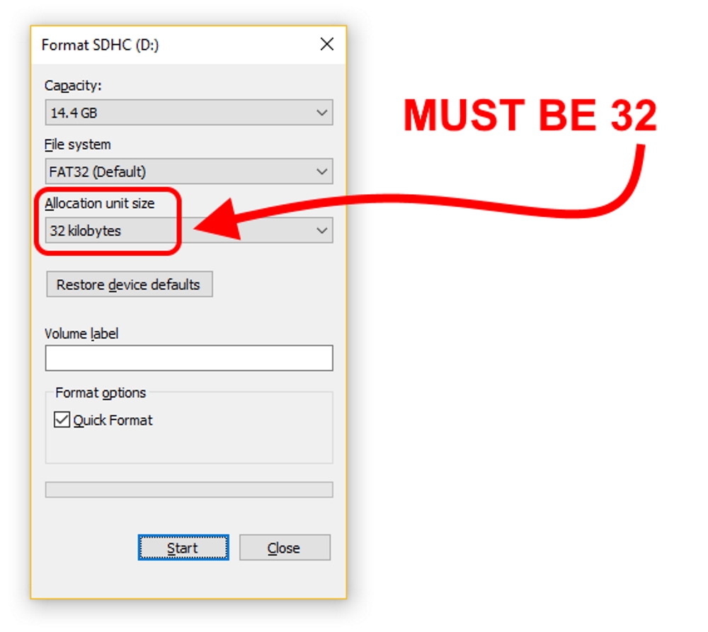
Formatting settings for Tsunami uSD card
What would I do differently for version 3?
Plan better for control panel access. Power worked out, but it was tight, and messy. Also, I’d like to have put access to programming lines and volume control without having to remove the front panel. It was stressful to think that it all had to be “perfect” before putting the faces on the panels, and that it’d be a pain to “rip” them off (velcro) for any adjustments.
Related to panel access, I would go with the RedBoard Edge for future designs like this. It has all of the necessary stuff ready to panel mount. This product was only offered via SparkX at the time, and unfortunately, it was out of stock. But now it is available via SparkFun, and so should be in stock all the time - wahoo!
RedBoard Edge would have been a good option for my control panels
I also should have made larger holes for cords into the control panels. I was only thinking about the cable diameter fitting through the wall of the frame; this lead to some unplanned drilling and wood shavings all over everything!
Ideally, I would have preferred more time to fine-tune the button control approach. Currently, the Pro Mini is listening to a resistor ladder on a single ADC. This required a fair amount of fine tuning the "windows" and de-bouncing. It currently will miss a very slight button press, but this actually isn't that common because most participant smack the arcade buttons with all their might!
I would have used a different power solution to avoid the clicking of the beefcake relays - maybe the Lumenati 3x3 array for lighting?
I also should have tested the LED brightness on MODE LEDs - those greens are way too bright! I used 330 ohm resistors on everything, and found that this was way too bright for our 10mm gumdrop greens. Also, the Large 7-segments are pretty darn bright, wish I could have toned those down a bit.
I probably should have used interrupt-based buttons for mode changing, maybe by hooking all the buttons up to an interrupt pin and keeping them connected to their own dedicated GPIO. This way, the interrupt would fire, you could read all pins and know which one was pressed. I was running low on GPIO (in order to keep my custom PCB universal for all three control boards), so I opted for the resistor ladder approach.
Adding LED limiting resistors into the custom PCB design would also have been helpful. It was a pain to wire those from LED lead to bare wire, and I'd hate to change them at this point, but if they were in the PCB design this would have been much easier.
What Next?
We're thinking about a potential revision to the Noisy Cricket to have screw pin terminals. We had trouble using even some small-gauge speaker wires with the standard 0.1" header breakout PTH pads. We ended up actually putting a screw pin terminal into the headers (as they are), and it gave us access to the GND/MONO-OUT that we needed, but this is less than ideal.
Our current in-house Simon trampolines could use an upgrade. I'm thinking about switching out the gumdrop LEDs for some sort of strips. Our Side-lit LED RGB strips would probably do the trick!
I wasn't totally satisfied with my mounting approach to proto board. Those PTH headers should hold up, but I'd love to have some more solid standoff holding everything together.
The Tsunami allows you to “pitch bend” sound files, and I’d love to have lighter jumpers have high-pitched sounds, and heavier jumpers have larger, low-pitched sounds (could be especially fun with frog sound bits).
We’re also considering expanding the project into "The Hive" – seven hexagonal trampolines all connected and making sounds. Oh yeah!
Finally, I'd like to explore more lighting techniques. The spotlights came out cool, but I'm curious to know what we could do with lighting systems under the trampolines and custom covers made from a clear material.
Even with all of these potential ideas for Version 3.0, we're still really stoked on the end result of Boulder Bounces. Every project is a learning experience, and this was definitely not an exception.
We'd also like to send a big thank you to the Museum of Boulder for the opportunity to collaborate on this project! For more info on the museum and all of the other exhibits, please visit MuseumofBoulder.org.
Boulder Bounces will be on display at the museum for the next three months, so if you get a chance, please come check it out!
For design files and code, visit the GitHub repository here:


Wow! Great job!
A few thoughts, though:
First, with my physical handicaps, I'll definitely pass on getting onto the trampolines, and just watch others do it...
I certainly sympathize with your tribulations from short schedules -- with nearly 40 years as an Engineer, I've had my share of schedules that are too short! (One memorable incident was a guy who came to me asking "how much would it cost to do it by this date?" -- my answer was $6.02x10^23 -- he asked how I came up with that number, and I said that for that much I was confident that I could build a working time machine, then use it to go back far enough in time to be able to do what he was asking for by the date he wanted!)
In situations where (accoustic) noise is a problem, switching (pardon the pun) from mechanical relays to solid state ones could help.
Brightness of LEDs can be a problem these days. (That's one of the things I like about using things like NeoPixels -- they can be modulated in software.). The 7-Segment Displays you're using are "common anode" -- although it's going to complicate the hardware a bit, you might PWM (Pulse Width Modulate) the supply to the anodes. You might end up with another ProMini to do nothing except control the brightness -- it could be "program and forget", or it could read a potentiometer (analog pin) and adjust the width, or (in my humble opinion the best option) it could look at a sensor for the ambient light conditions, and adjust the pulse width accordingly. Even better, it could look at which digit is active and adjust for brightness variations. (Sidelight - I noticed that some of the comments on the displays are 9 years old! Not a bad product life! I suspect SF doesn't sell many of them, but they're sure something than when you need it, you definitely need it! I have great respect for SF for keeping them in the catalog.)
One last thought: It seems to me that it might be a good idea to mechanically tie together the three trampolines. The approach I'd use would be to go down to the local auto parts store and get a few "hose clamps" of the sort that have a worm screw to tighten them. They're plenty strong enough, and can easily go around the legs of the trampolines, are (relatively) easy to adjust, and are flexible enough to conform to some pretty odd shapes. Oh, by the way, if you can't get ones that are long enough, take two (or more) the exact same size and "unscrew" them all the way and "daisy-chain" them.
Thanks for your feedback 773!
Solid State Relays are a smarter option, for sure. I should have looked into those before committing to our beefcake relays. I suppose these SSRs would do the trick: Solid State Relay - 40A 3-32V DC Input. They seem a little overkill, but I was switching the mains power to the spot lights.
For the LEDs, I definitely agree that using some sort of addressable is the better option. I do like the look of the old fashioned 10mm gum drop LED, though. I wonder if there is an addressable 10mm diffused PTH out there?
Either way, I'm planning on doing some experimenting, and giving a few suggested resistor values for 3.3V and 5V on our LED product descriptions. Even just knowing "barely on", "pretty bright, and "partially blinding" would be helpful as a starting point.
The large 7-Segments are indeed fun. We have one right near my workstation actually that inspired me to use it in this project. Nate installed a "speed trap" that's always popular on the tours. You can read his tutorial on that here.
About your thought on tying the trampolines together. Hose clamps are a brilliant idea! We did use some metal brackets to mount them to the wall studs, but I think we just used zip ties to connect them to each other.
Thanks again and I appreciate your input! -Pete
Hi Pete! (BTW, I think you were the guide when I toured SF back in November -- I was the guy on the scooter.)
As for the "NeoPixels". I've used a bunch of the 5mm ones. Our friends over at Adafruit have some 8mm ones, which their website claims I "last purchased" about 4 years ago, though I don't think I ever actually used them for anything. I don't know of anyone that has them in 10mm (I have a project in mind that 10mm would be good for), though I haven't really looked that hard.
Experimenting with balast resistance values for LEDs is an ideal use for a Decade Resistance Box, though you can "cheat" and just use a pot and then measure the value. (If you want an accurate value, don't trust the markings on a Decade Resistance Box, even if you have one that is NIST-traceable: use a DMM to measure the resistance.)
Yes, I recall the "speed trap"! Fun to see how fast my scooter would go! ;-)
If you used "heavy duty" zip ties, that shoud suffice, though I still lean towards the hose clamps.
Hey, what's a couple billion terabucks amongst friends? ;-)