Hackbot in the Morning
Pretty quiet around here at 7 a.m. Maybe I can whip up a quick python-fueled, Pi-based bot? Oh, yeah - hot glue features prominently in this build.

I love coming in to work early; normally I get in around 6:45 a.m. Very few people are here at that time, and the ones that are? They get it. It's about as close to freedom a working adult can expect.
On a particularly quiet morning very recently, I found myself thinking, "I've never made a bot with a Pi... isn't that one of the things that everybody's gotta do sooner or later? I wonder what it takes to actually get something up and running."
So I decided that, with minimal effort and materials expended, I would give it a shot while there was nobody here to tell me otherwise – nothing fancy, just a platform that'll drive around, to which I can ultimately attach more junk (it started with some junk reclaimed from other projects). Check the end of this post for a consolidated list of items used.
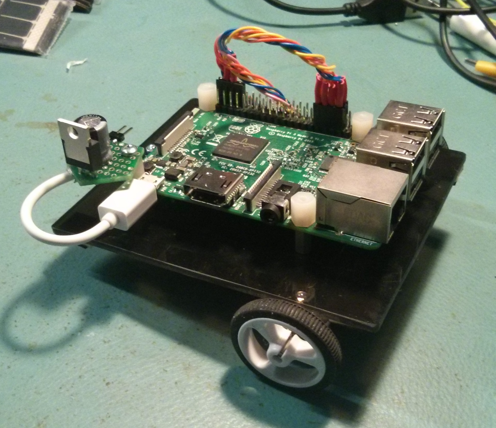
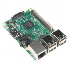
I started off with a Raspberry Pi 3 I mounted to an acrylic plate to try to give it some weight to hold it down when there's a slew of cables stuck in it. I hit my pile of junk in my basement for more parts... and I came across this old project:

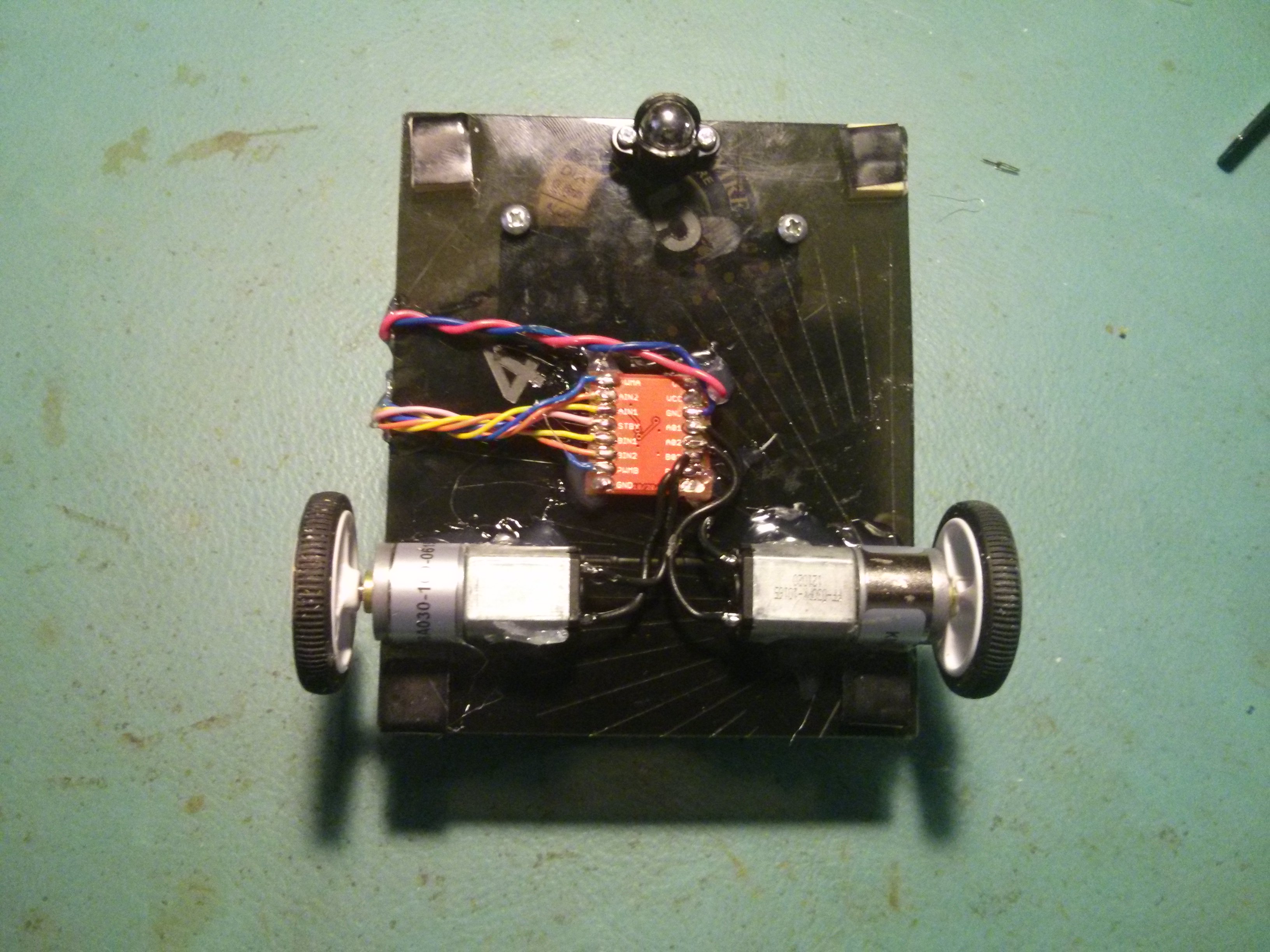
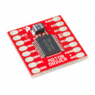
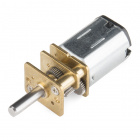
That there (above) is the remains of my "Little Dude" project I did a video for a while back, using servo wheels glued together as pulleys... good times, good times... Anyway, that's a pair of gear motors (ratio unknown, whatever - let's rock!) wired up to a TB6612 dual-channel motor driver good to 1.2A per channel. Sweet! This bot was just about building itself!
I figured could mount the motors and driver directly onto the acrylic with hot glue, although if anything got too hot, it would fall off. I decided to just really gum up the motors so any heat couldn't melt all of the hot glue and stick to the edges of the driver board. This bot wouldn't be drawing that much current. If I remember right the stall current on the motors is around 330mA, and we'll be nowhere near that driving this little beastie around the office.
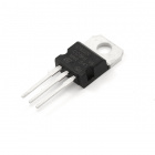
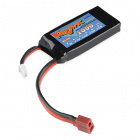
When it came to power, for initial testing I'd have to have all the cables and junk plugged in anyway, but Hackbot needed localized life support if he's eventually going to romp free... not to mention headless operation. I could have started it with all the junk plugged in, then yank the keyboard, mouse and monitor out and set it on the floor, but that was definitely a short-term solution. I let that part go while I got the rudidments in place. In the meantime, I had to make a little regulator circuit with a 7805 – that should be good to an amp and a half, so it should cover me for the Pi and the motors. But a two-cell lipo is about 8.4V fully charged, and at a guess I'll maybe draw 500mA average (totally ballparking here), giving me (8.4V - 5V)*0.5A = 1.7W to dissipate on that TO220. It would probably get hot unless I heatsink it.
Programming this in Python was easy enough, as it's just GPIO manipulation. I wasn't going to try and PWM the motor driver, as I had the gear motors and I knew they were slow. If they were faster, I might have had to worry about feeding them PWM to control the speed.
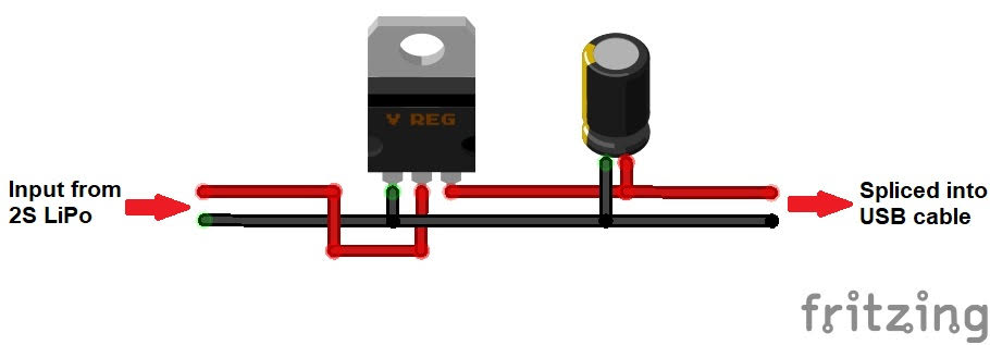
I then created a wiring diagram of sorts:
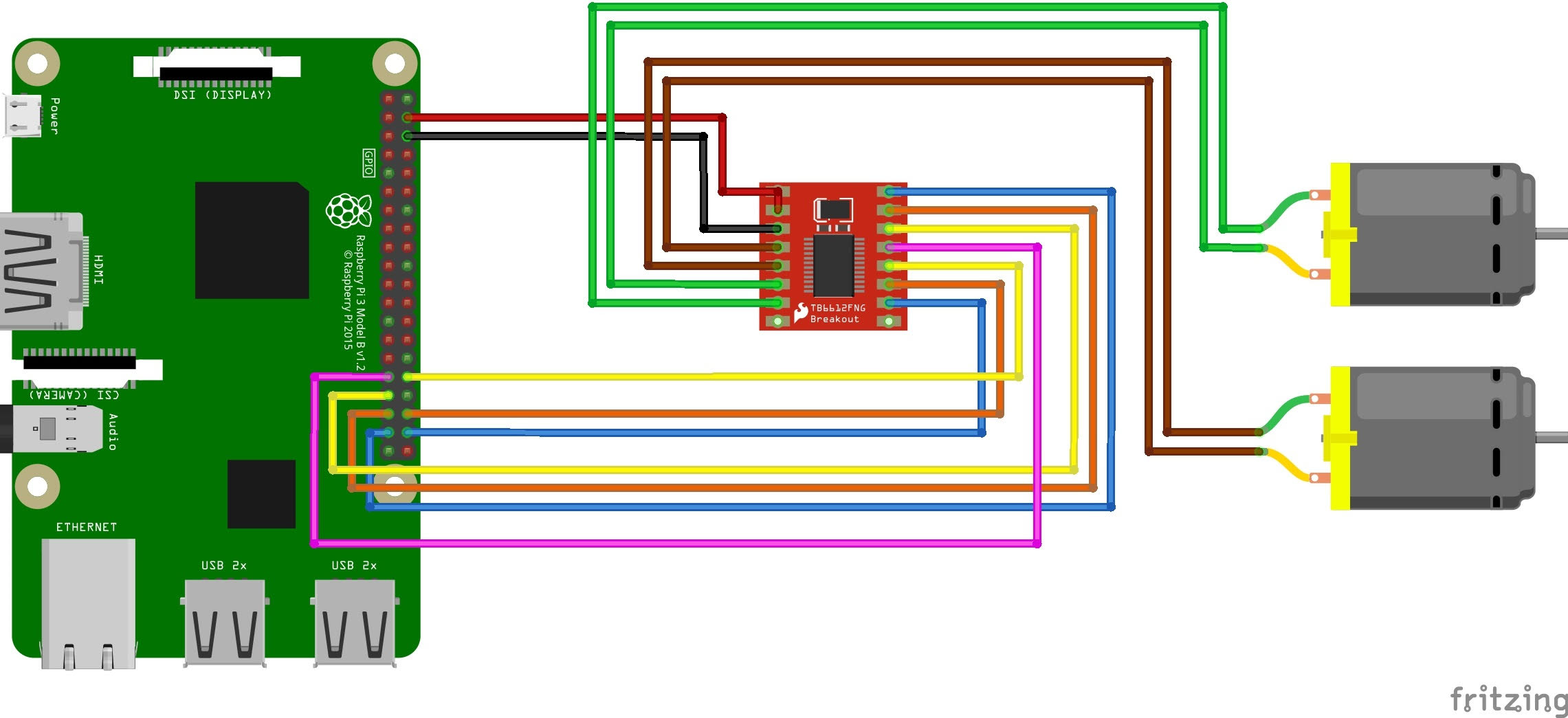
The hookup was simple enough. Each channel on the TB6621 is driven by three pins: [A/B]IN1 and [A/B]IN2, which determine the direction, and PWM[A/B], which allows you to adjust the speed of the channel through a PWM signal applied here. There's also a standby signal (STBY) that will enable/disable both channels. That's seven lines total, and they all get a GPIO line.
Running motor power through the RasPi wasn't really the smartest thing I could do, but 1) the motors were originally rated for 6V and the lipo's going to be more, and 2) I bet it wouldn't be a problem at this stage, (though I wondered if I'd get motor noise back to the RasPi). Checking the TB6621 datasheet showed lots of noise-suppressing diodes on the motor outputs. Clearly, destiny wanted me to do this.
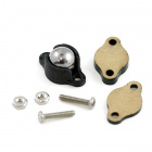
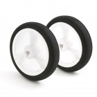
There were still a couple of things I needed to make this viable: wheels and a caster. Oh sure, I could have used those hot-glued servo wheels that were originally on the motors (check the first pic above) for some extra jank-factor. But I felt like I was already up against enough sketchy design, so I just bought them. Pro tip: that caster is a little tight at first. You can loosen it up by clamping that ball between the plastic with a pliers and giving it a little squeeze (not too much, as you can't un-squeeze it).
After some hot glue magic plus a minimum of wiring, the bottom of Hackbot looked like this:
The top looks like this:
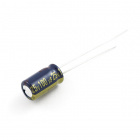
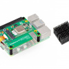
Now I had the physical platform close, but I still had to make a little regulator board. I figured it really didn't need to be anything special, just an L7805 regulator, plus an electrolytic cap of 100uF or so on the output oughta do it. I gave it a two-pin male header to plug into the two-cell lipo, and snatched a micro USB plug from some unsuspecting cable to connect to the 5V out.
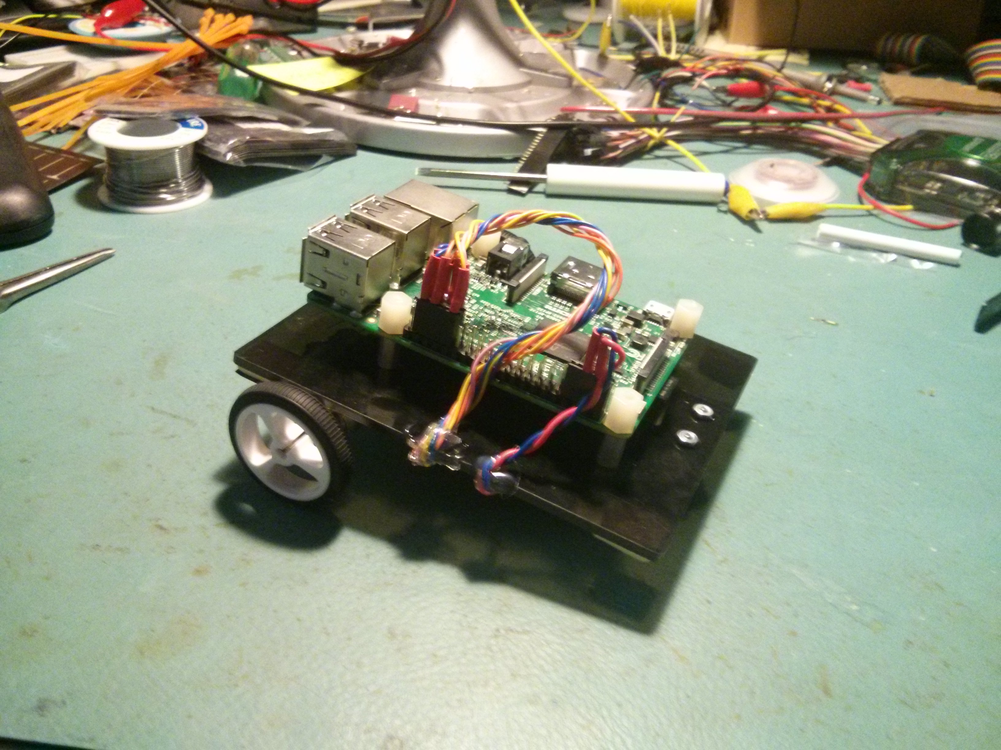
Then I mounted it on one of the stand-offs holding the RasPi down.
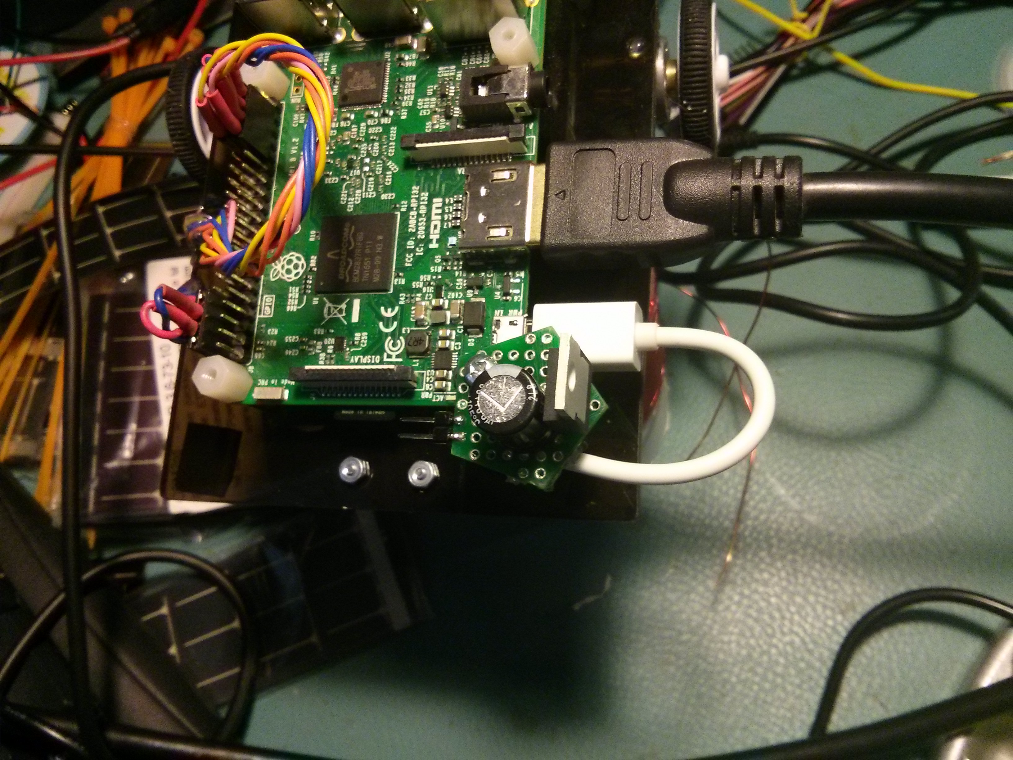
Another view:
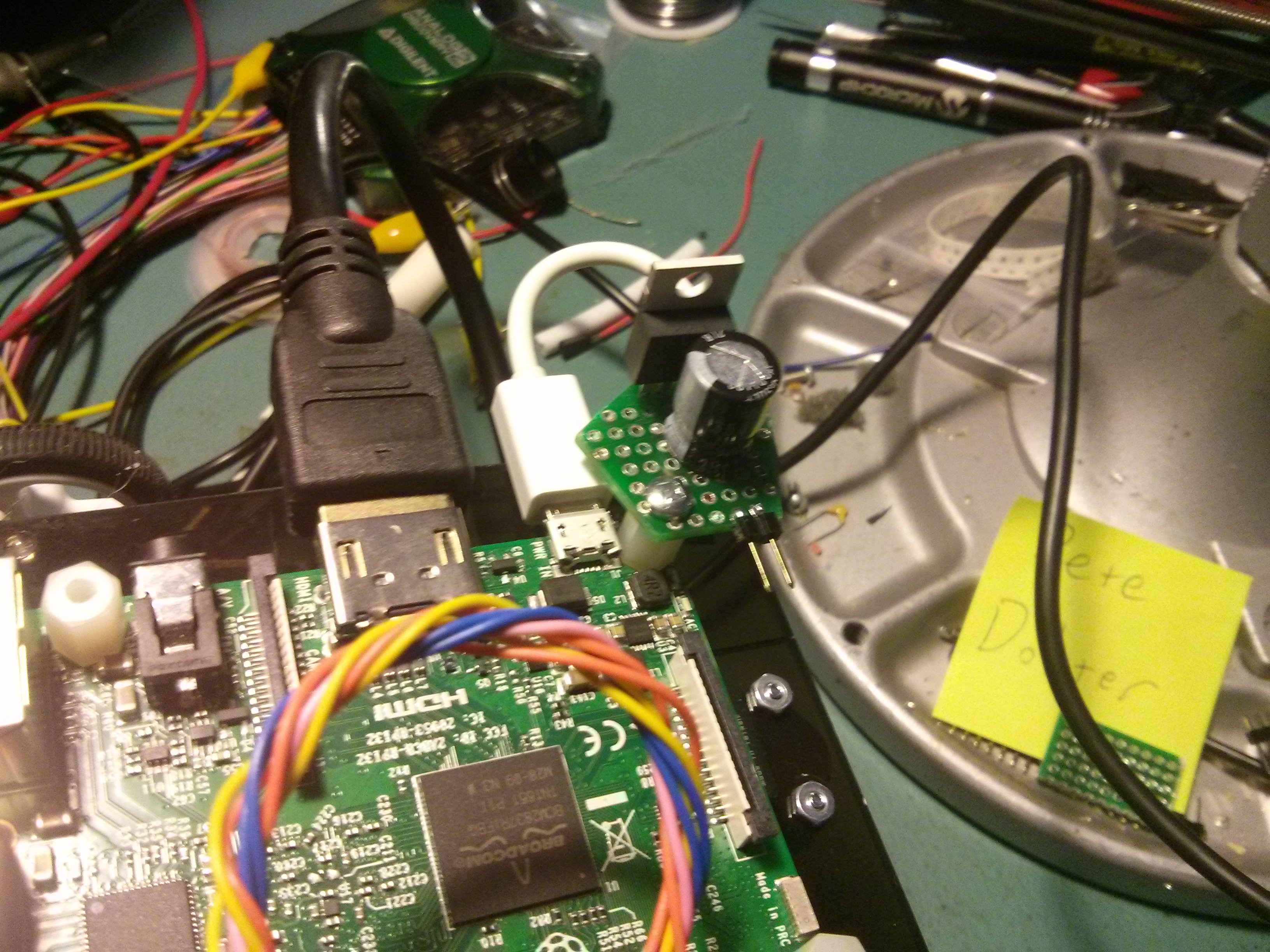
The PCB that the regulator is mounted on is from an old product line of shaped PCB's that we used to have, that one being a pentagon. It was lying around, so I used it. The idea here was that the battery will sit on top of the RasPi in some fashion (I can work out the specifics later) while plugged into that two-pin male header you see there.
From there, I turned to code. There's definitely more junk to add, but that's for another day. The car's got wheels, right? Let's go driving!
#Hackbot.py
#Just a little test code to run around the floor a bit

import RPi.GPIO as GPIO
import time

#a couple of delay constants
leg = 2
turn = 0.5

#set up control pins for motor driver
STBY = 31
AIN1 = 33
AIN2 = 35
PWMA = 37
BIN1 = 32
BIN2 = 36
PWMB = 38

GPIO.setmode(GPIO.BOARD) #use board pin numbers

#set the GPIO's to outputs
GPIO.setup(STBY, GPIO.OUT)
GPIO.setup(BIN1, GPIO.OUT)
GPIO.setup(AIN1, GPIO.OUT)
GPIO.setup(AIN2, GPIO.OUT)
GPIO.setup(BIN2, GPIO.OUT)
GPIO.setup(PWMA, GPIO.OUT)
GPIO.setup(PWMB, GPIO.OUT)

#set initial condiions, STBY
#is low, so no motors running
GPIO.output(STBY, GPIO.LOW)

GPIO.output(AIN1, GPIO.HIGH)
GPIO.output(AIN2, GPIO.LOW)
GPIO.output(PWMA, GPIO.HIGH)

GPIO.output(BIN1, GPIO.HIGH)
GPIO.output(BIN2, GPIO.LOW)
GPIO.output(PWMB, GPIO.HIGH)

#movement is governed by the 4
#following functions.  These will
#go into their own library, ultimately.
def go_forward(run_time):
    GPIO.output(AIN1, GPIO.LOW)
    GPIO.output(AIN2, GPIO.HIGH)
    GPIO.output(BIN1, GPIO.LOW)
    GPIO.output(BIN2, GPIO.HIGH)

    GPIO.output(STBY, GPIO.HIGH) #start
    time.sleep(run_time)
    GPIO.output(STBY, GPIO.LOW) #stop

def turn_left(run_time):
    GPIO.output(AIN1, GPIO.HIGH)
    GPIO.output(AIN2, GPIO.LOW)
    GPIO.output(BIN1, GPIO.LOW)
    GPIO.output(BIN2, GPIO.HIGH)

    GPIO.output(STBY, GPIO.HIGH) #start
    time.sleep(run_time)
    GPIO.output(STBY, GPIO.LOW) #stop

def turn_right(run_time):
    GPIO.output(AIN1, GPIO.LOW)
    GPIO.output(AIN2, GPIO.HIGH)
    GPIO.output(BIN1, GPIO.HIGH)
    GPIO.output(BIN2, GPIO.LOW)

    GPIO.output(STBY, GPIO.HIGH) #start
    time.sleep(run_time)
    GPIO.output(STBY, GPIO.LOW) #stop

def reverse(run_time):
    GPIO.output(AIN1, GPIO.HIGH)
    GPIO.output(AIN2, GPIO.LOW)
    GPIO.output(BIN1, GPIO.HIGH)
    GPIO.output(BIN2, GPIO.LOW)

    GPIO.output(STBY, GPIO.HIGH) #start
    time.sleep(run_time)
    GPIO.output(STBY, GPIO.LOW) #stop

#Then we make a simple driving patern and loop
try:
    while True:

        #go forward
        go_forward(leg)

        #turn right?
        turn_right(turn)

        #go forward
        go_forward(leg)

        #turn right?
        turn_right(turn)

        #go forward
        go_forward(leg)

        #turn left
        turn_left(turn)

        #go forward
        go_forward(leg)

        #turn left
        turn_left(turn)

        #reverse
        reverse(leg)

except KeyboardInterrupt:

    GPIO.cleanup()
To run this, I powered the Pi from my two-cell lipo with all the cables plugged in, just long enough to open a terminal window and run that code. Then, I quick-like yanked all the cords out, put it on the floor and let-r-rip!
Look at that thing lay it down! Am I right?? Those motors are really slow, and we don't sell that particular one anymore. I want to say they're geared 300:1...? Or maybe 300RPM? The concept is hereby proven, and I can change those motors out if I really want to.
Things I could have done better
1) Like I knew it would, the regulator gets hot. Not so hot that I can't touch it, but I don't want to for very long. The current draw is around 315mA sitting idle, and around 500mA-ish when we're driving around, so it's dissipating over 1.5W when driving. That's a bit much for a TO-220 package by itself, so I should put a hunk of metal on it.
2) Running motor current through the Pi, while convenient for today, is kinda dumb for the long term. I can get away with it for now because the motor current is relatively low, but the current path between the USB plug and 5V on the header is in no way designed to do this. I should really run the motor voltage directly from the regulator.
3) Headless operation: plugging cables in and out to do this is no good. Pinocchio wanted to be a real boy; so does Hackbot.
4) Hot glue. You know what? The hot glue is working for me. Saved me a ton of time.
Those are the things that gotta happen before anything else gets added. What to add?
What comes next
There's a bunch of GPIO left available on the Pi header, including SPI, I2C and UART interfaces, so there's a lot of room for adding junk. I can't add anything particularly analog, but I don't think I need to. But anything with a digital interface is fair game – distance/proximity sensors, GPS, environmental sensors... it just depends on what your ultimate goal is, or what sensors you want play with. This would make an interesting mobile test platform for new gear.
For myself, I'm less about getting tiny bots to do my will, and more about, "That thing is sweet! I wish I was two inches tall so I could get in and drive!" So it'll probably get a camera at some point, probably an OSD to keep me updated with various info. Then LEDs, Troll hair, googly eyes...
Recap: Materials Used
To extricate the list from my story-telling style:

Some reading you may appreciate
How to Solder: Through-Hole Soldering
This tutorial covers everything you need to know about through-hole soldering.
TB6612FNG Hookup Guide
Basic hookup guide for the TB6612FNG H-bridge motor driver to get your robot to start moving!
Python Programming Tutorial: Getting Started with the Raspberry Pi
This guide will show you how to write programs on your Raspberry Pi using Python to control hardware.


So how long did it take? What time was it rolling on the floor?
6:45 seems reasonable to me. I can't get in that early because my train doesn't arrive until 7:15. then it's a 20-minute walk from the station. That's still earlier than most here, though. The big problem with getting in early is leaving early. All the gang that arrives after 10 starts acting as if you're deserting them (ever try to duck out to catch your ride home to a chorus of "You Picked a Fine Time to Leave Me, Lucille"?).
6:45 am??!!?? If I'm at the office at that time, it means I've been there all night, and it's past time to go home! ;-) ;-) ;-) (Midnight at the office wasn't that uncommon for me, though now I'm retired.) Sheesh...
Anyway, great project, Pete! A couple of quick comments: I'd sure be inclined to use a Raspberry Pi 3 B+ for this, as then you can use the WiFi to control it "headless". The other thing is I'd strongly recommend adding a small, say 0.1uF ceramic cap on each side of the 7805, to get rid of any high frequency noise. I recall a problem with the first computer I built back in the mid 1970s that when I finally got a 'scope I foound I had about 7V peak-to-peak at about 3MHz riding on the 5V line... the TTL stuff was NOT happy with that!