Getting a Module FCC Certified
The costs and time required to get the world's first open source BLE module certified with the FCC.

For years SparkFun was wary of getting a product fully FCC certified. The process was always seemed unknown and prohibitively expensive. We've written about the FCC requirements for products and hobby projects the past but with the development of the SparkFun Edge and the creation of Artemis it was clear that it was time to venture into uncharted territory. We hope you can learn a little something from us. This is a three part series covering the creation of the Artemis SMD module, getting an RF shield made (twice), and getting through the FCC certification process.
Getting Artemis FCC Certified
Now that the module was designed and the RF shields were working, it was time to find a test facility that could help us both test the RF output for regulation compatibility and file the application with the FCC. Never having done this before we wondered how to begin. In a similar vein to finding an RF shields manufacturer, I googled and cold-emailed a handful of places to see what it would cost to get an intentional radiator (Bluetooth) module certified with the FCC. I received a variety of replies across a length of weeks. It was obvious some places were too large to care about dealing with SparkFun.
I get the impression that one of the largest costs to these companies is dealing with noobs; either poorly designed devices or poor documentation can create a headache for the test house to complete certification (if possible) and make the client happy (if possible). It is more lucrative for them to work with companies who regularly turn out products that need straightforward certifications.
Luckily, and gratefully, one company had heard of SparkFun and was willing to chance working with a company who had never certified a module before. They have requested not to be named so we will call them Unitato.
After a brief call with Unitato, I had a clearer picture of how the FCC process would work. It went something like this:
- SparkFun gets a quote from Unitato and pays the 50 percent down payment. The six-week clock begins.
- SparkFun designs and assembles a carrier board for the Bluetooth device and ships it to Unitato. Unitato will then ship the device on to a larger batch testing facility (also known as a TCB or Telecommunications Certification Bodies) in China where they test hundreds of devices a day.
- Simultaneously, SparkFun would begin creating documentation that FCC requires to file an application.
- Forward all necessary docs to Unitato so they can compile and submit the application to FCC.
- Unitato and SparkFun then deal with any responses or issues the FCC may have.
That seems doable! So we got a quote that looked something like this:
- FCC Part 15 Testing & Certification (FCC Part 15C: 15.212, 15.203, 15.205, 15.207, 15.209, 15.247 & 2.1093 (RF Exposure) : $4,000
- ISED Testing & Certification (RSS-247 | Issue 2, Sections: 5.2, 5.4, 5.5 & RSSGen | Issue 5: 8.3 8.8, 8.9, 8.10, ICES 003) : $3,000
- Canadian Agency Fee (one-time fee, but comes with annual renewal fee. Canada requires all non-Canadian companies have a registered agent in Canada) : $600
- CE Testing & Certification (CE RED | EN 300 328 (v2.1.1), EN 301 489-1 (v.1.9.2) & *-17 (v3.2.0), EN 62479:2010) : $2,800
- CE Testing & Certification (CE LVD | IEC 62368-1:2014) : $1,800
- China MIIT Testing & Certification : ~$3,500
- Japan MIC Testing & Certification : ~$5,000
You can see how the fees can add up quickly but we decided to go with FCC/ISED/CE for $12,200. Not bad, and about half of what we feared we would need to pay. I received a few quotes from other companies that were double and triple this amount so we were initially skeptical. I suspect the pricing fluctuates greatly based on who you know at the test facility and how much work you've done with them in the past. As Unitato and I worked together it was clear they were an efficient, fast-paced shop. We will certainly use them again in the future.
In addition, the same module but with different antenna configurations can be tested to save time and money. You will often see the same module from a given manufacturer offered in three flavors: PCB antenna, chip antenna and external antenna. We originally floated the idea of "series testing" three modules but the costs got a bit high. The additional testing would be ~$2,000 per model (so an additional $4k) in testing fees, and another $2,500 to $6,000 in filing fees. Because the Apollo3 is really meant for low power it didn't immediately make sense to have a u.FL option where max range was king. If users needed a long-range BLE module there are much better, higher power options on the market, and a trace antenna based module is nice, but the 2.4GHz antenna is a very small fraction of the overall BOM. Selling a lower-cost trace antenna module would be worth the headache of managing two SKUs. So for this project we decided to keep testing down to one model.
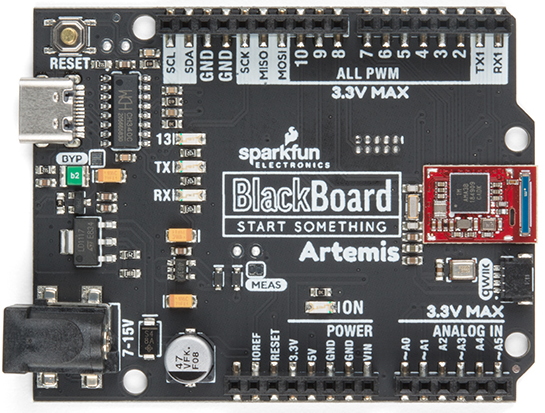
The original BlackBoard Artemis
With $6,100 sent off in the mail, it was time to get the carrier board ready. The test facility does not care about what the carrier board does, all it needs to do is put the device under test into various RF emission/test states so that the RF energy can be measured at different frequencies. The test facility doesn’t need (or want) the bare module, and the carrier board can really be anything as long as it is indicative of how the product will be implemented by an end user.
Serendipitously we were designing a plethora of carrier boards for Artemis. Namely, the BlackBoard Artemis, ATP and Nano. We had samples of the RF shield (without laser etching) from our metal stamper so we built up a few Artemis modules with blank shields and a few BlackBoards with the shielded Artemis. We were able to verify that the Bluetooth connectivity worked to nearly 100m outdoors, but we didn’t have the necessary anechoic chamber to do any real quantitative testing.
Additionally, we knew we needed a test mode where the TCB could control the BLE radio and send a continuous modulated signal at 2402 MHz / 2440 MHz / 2480MHz for the FCC and ISED testing. But how to put the radio into this very odd state? Luckily, Ambiq rules, and knows that their end customers (like SparkFun) need to get a product FCC certified. They wrote a large document called RF Test Guidance for Apollo Based Equipment detailing how to set up and test Apollo-based products. They also created firmware called uart_ble_bridge that configures the radio into test mode and allows the test facility to send low level HCI commands over serial to manipulate the radio. We got lucky: very few silicon companies provide this level of firmware support, so check with your vendor before you embark on your own module development.
I whipped up an FCC/CE Testing Procedure document that was included with the carrier board shipment so that the test facility could talk to the BlackBoard Artemis carrier board.
With hardware now sent off to Unitato, we had a five-week wait while the device was tested. In the meantime, we created the variety of documents needed for the FCC application.
Here is the list of documents created or compiled before applying to the FCC:
- Intake Form
- Integration Guide
- Schematics
- BOM
- PCB Silkscreens / Component Designators
- Theory of Operation
- Block Diagram (show all oscillators, crystals, RF and ICs)
- ID Label Drawing
- Written Instructions and Firmware For Operating Device in Wireless Test Mode
- PCB Material Safety Standards
Most of these are self explanatory but here is the description of a few.
Intake Form:

The Intake Form is a massive spreadsheet used by the test facility to know who you are and what you’re testing. Lots of questions and nitty gritty details that required a lot of research: What is the exact PCB FR4 material? What is the Antenna Gain? What Bluetooth Version?
Integration Guide:
The Artemis Integration Guide was the most work, but this document needed to be created regardless of FCC testing. Since we planned to sell the bare module we needed to create a guide for users so that they could successfully create a PCB footprint, route to the module, deal with the antenna, power the module, etc. All of this content did double duty as the Integration Guide submitted to the FCC.
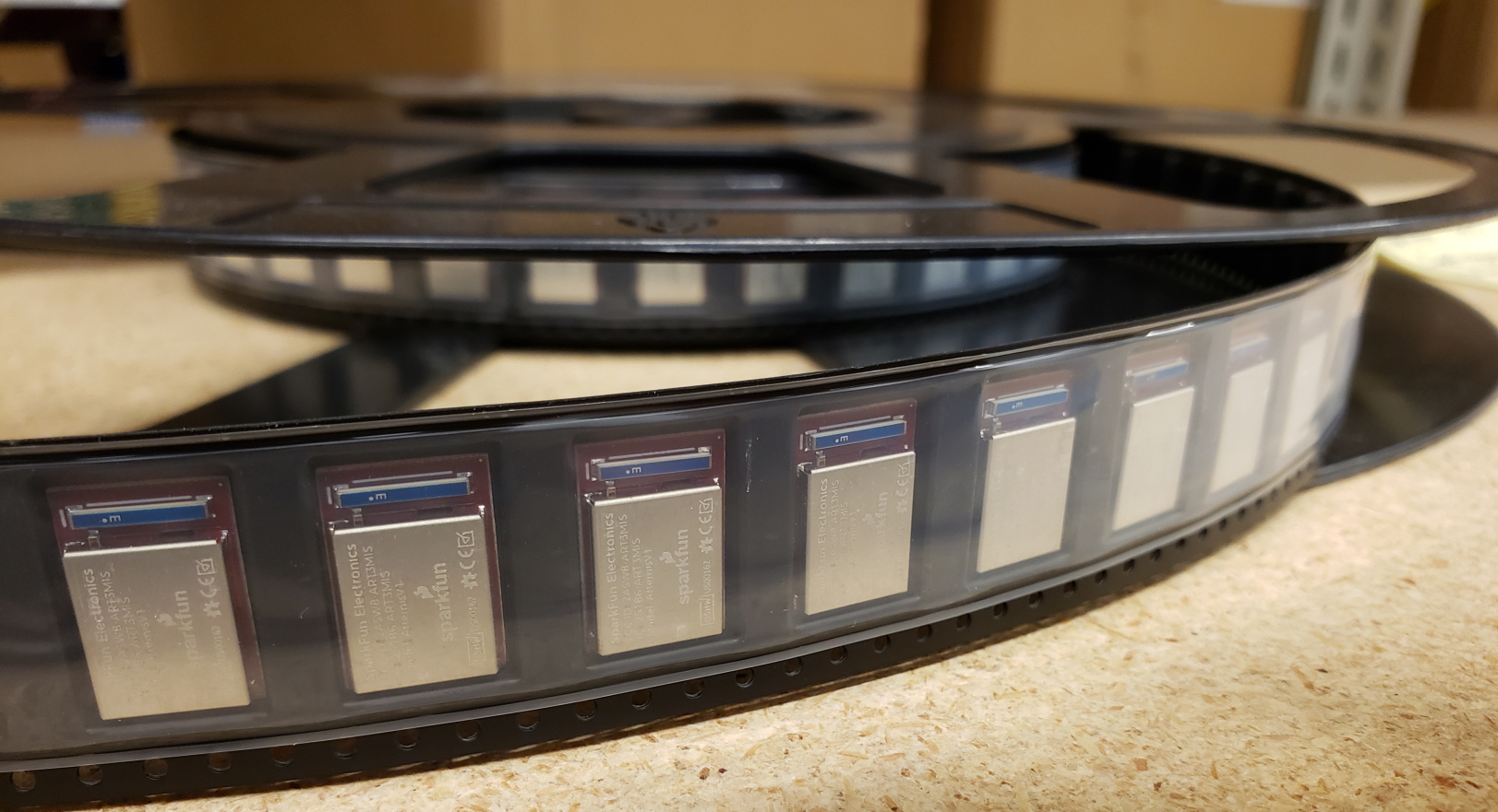
One interesting piece of this guide was the Tape and Reel specification. If we expect third parties to buy and use the Artemis in their assembly they’ll need to use our T&R in their pick-and-place machines. Luckily, the same company who we outsourced our tape and reel packaging to was willing to allow us to use their 3D tape design in the Integration Guide, saving the work of recreating it.
Theory of Operation:
We were told the Theory of Operation should be short and sweet. Just the facts.
Block Diagram:
The easiest document was the block diagram showing the basics of Artemis.
Written Instructions For Operating Device in Test Mode:
As mentioned earlier, we created a simple testing procedure to help the test facility hook up to and control the carrier board - not a hard document to create, but time consuming none the less.
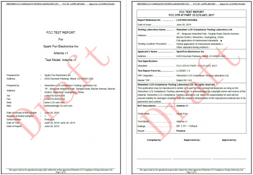
Sweet, sweet FCC draft reports
Once all these documents were compiled, we waited for the test facility to get us our report. At week five, right on time, we passed testing and received a draft of the report. And oh boy was it a report! Counting the ISED, FCC and all the photos of the setup, it was nearly 100 pages of graphs and images.
With all the documents in hand, Unitato submitted the application. After about a week we received the wonderfully oblique feedback from the FCC:
- Add Regulatory Language - This was some boilerplate changes to the integration guide in both English and French.
- More Usage Details - “how to use the device” in the integration guide.
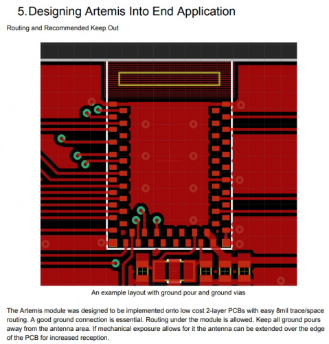
Thankfully Unitato guided us through the necessary changes. I added a 'Programming' section and a 'Designing Artemis into End Application' to the integration guide and we resubmitted.
Timeline to FCC
Like with many projects, there were days of furious effort followed by weeks of silence. The overall timeline looked like this:
- June 1st - 50 percent down payment sent to Unitato
- June 5th - Carrier board and module received by TCB
- July 10th - Testing completed and draft report released
- July 16th - Application sent to FCC
- July 23rd - FCC requests Integration Manual language changes. Feedback addressed.
- August 9th - More Integration Details and 'Spurious Emissions Testing Cases Description Section' requested by FCC.
- August 12th - Warning section language change requested by FCC.
- August 16th - 2ASW8-ART3MIS listed on FCC. A few days later 25186-ART3MIS listed on ISED.
Two and a half months is not terrible in the grand scheme of things. If and when we certify another product I imagine we could shave a few weeks off.
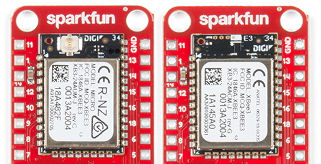
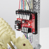
A few fun notes before we leave you: Always check the test reports for errors! While reviewing the FCC draft reports we found some fun errors:
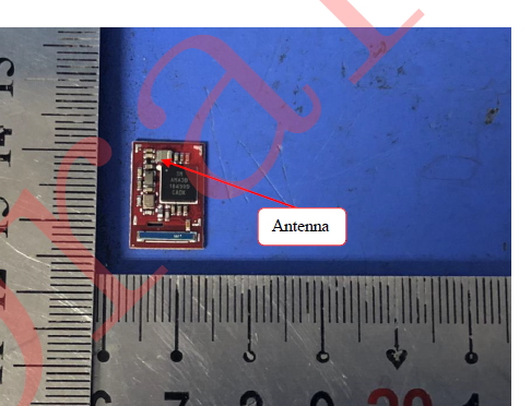
For those readers who haven't spent three months staring at the design of Artemis it may not be obvious but that is not the antenna, that's an inductor. The antenna is the blue thing at the bottom. The test facility may just be moving too fast or the person responsible for creating the images might just not know what an antenna is.
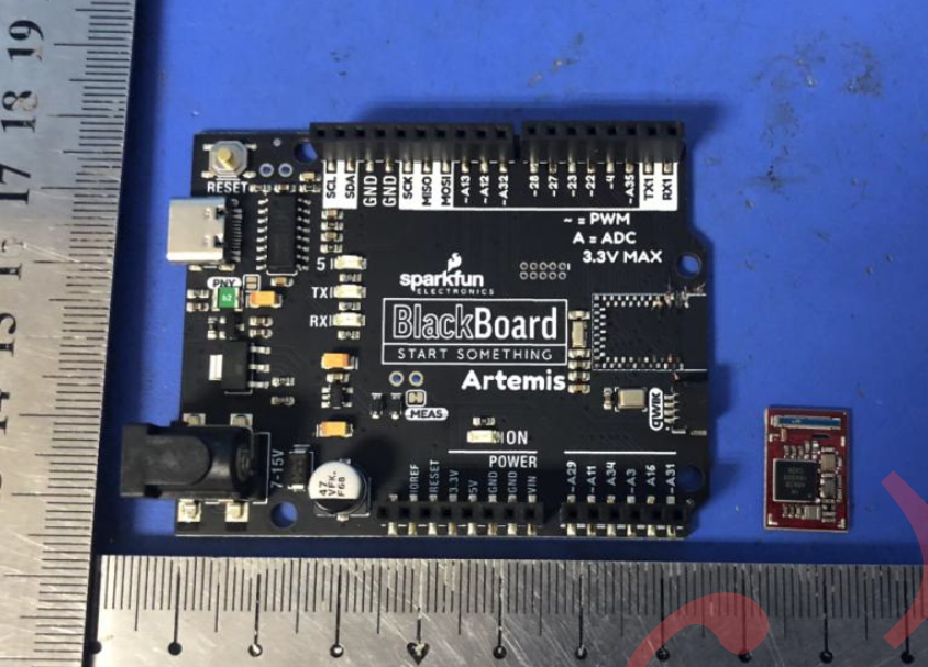
The image above does not have an error per se, but we sent the test facility an assembled BlackBoard with a fully-shielded Artemis as well as a bare Artemis module. For reasons that escape me they manually removed the shield and, probably with great difficulty, removed the SMD Artemis module from the carrier board.
We hope you've enjoyed reading! Let us know what experiences you've had getting products through FCC approval.


We have several products that have gone through the FCC throughout the years (all intentional radiators, all used in airborne applications). The costs you outlined seemed very reasonable. This is probably one of the best summaries I've seen and I am very impressed you published it (kudos to you). Since going through the process is pretty time consuming, many companies consider the experience more inline with intellectual property (just thought others that are not as familiar can really appreciate what you've done). We normally go to a local place for testing, but I know of one product that was more "commercial" and went to one of the "aggregators" so the testing was actually done in China. I can tell you that one thing we learned is that some test houses over there (I won't say all) take very detailed pictures and documentation of everything they test and later on pass that information to local design houses. It is kind of the "cost of doing business" with companies over there (but you probably knew that already).
@nate
Interesting!
I've worked with government agencies and various certification processes before, (but not the FCC), so "ah feel yer pain!"
I appreciate the time and effort you put into getting this device certified. Many other companies would just punt, say it's a subassembly, and leave the end user to certify it themselves.
This whole series on the Artimus and the efforts you folks put into it is extremely interesting in its own right.
The next time I have a client who thinks that RF certification is just a matter of filling in an application, writing a check, and stuffing everything in an envelope, ("Really now, how complicated can that POSSIBLY be!!"), I'll just point them to your article and watch their jaw drop
Thanks again for such an awesome job!
Jim "JR"
Thanks for sharing, Nate!
A few years back, there was an "expert" who wrote a book (actually an "e-book") on getting FCC (and other) certifications, and "published" it on one of the "crowd-funding" sites. It'll be a few days before I have time to look up my old e-mail about it.
The FCC maintains a public, on-line database of the stuff that's been certified. (In this case, use "2ASW8" as the "Grantee" code, and for the "product model" be sure to include that hyphen in "-ART3MIS"!). I've used the database several times to dig up manuals for stuff...
Anyway, thanks again, Nate, for sharing, and congrats on getting through it!
Thanks Nate, sharing this is Sparkfun at its best !
That test report has a lot to say about Dell and Bluetooth 4.0 too.