No, this has nothing to do with Tron. This image below is actually a time exposure of the UAV Development Board spinning on a record player. The green LED was used to measure magnetometer latency, similar to the strobe light method of measuring engine timing. More on that later...

The UAV Development Board (aka UDB) has been around for some time now finding its way into everything from RC-airplanes and RC-helis, to sailboats and rockets. Alone, the board is a three axis IMU and with the addition of a GPS, the board turns into a complete UAV controller. We now have a brand new revision called the UDB4.
The most common application for the UDB is RC airplanes, where the UDB is connected in between the radio receiver and servos/motors on your RC airplane. It can be switched mid-flight to work as a stabilization unit (to assist the human pilot -- great for smooth landings!), as a full autopilot to fly the plane through a user-configurable 3D flight plan, or can be disabled to give the human pilot full control. However, the board is not limited to simple RC planes with throttle, elevator, and rudder control. Pretty much any fixed wing RC plane could work, including delta wings, jets, gliders, aerobatic planes, and FPV systems with live video feed. Multi-copter support is in the works.
There is great documentation on the UDB project. The main points of interest are:
- UDB Product Page
- UDB Google Code Page (main UDB firmware home page)
- DIYDrones UDB Page
Coming up in this blog post, I will go over the history of the UDB and then talk a bit about how the developers tested and refined the system using some very interesting testing techniques.
History of the UDB
There has been a handful of revisions of the UDB over the past 5 or so years, so let's take a look back at memory lane.
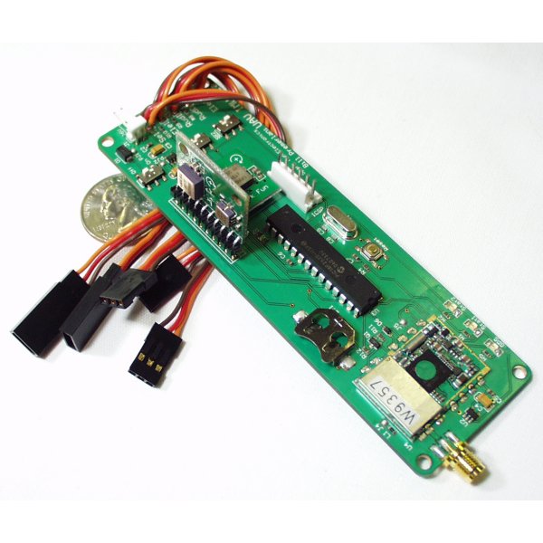
This is one of the first (v1) UAV dev boards (GPS-00707). All of the firmware was written in assembly and there was only 2 gyro and 2 accelerometer axes for the IMU. Notice the partially unshielded SMD ET312 GPS and 8-bit PIC18F2520.
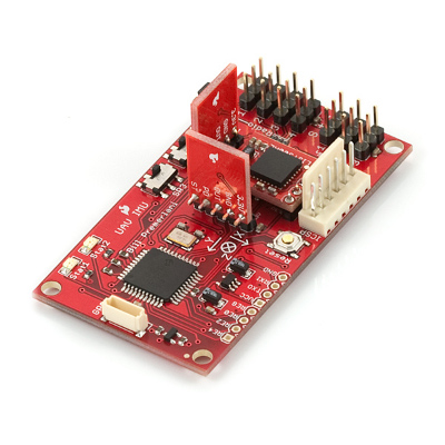
For v2, the GPS was moved off board and a full 6 axis IMU was implemented (3 axis gyro, 3 axis accelerometer). We also moved to a much more powerful 16-bit dsPIC and the source code was ported into C.These changes allowed the developers to start doing some really interesting things. For instance, implementing a DCM (direction cosine matrix) algorithm. At this point, the UAV Dev Board was turning into a extremely powerful system.
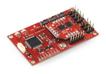
The v3 board incorporated multiple axis sensors in flat packages. Although we still used the same main board sub assembly as v2, the three gyro daughter boards representing each axis were replaced by a single daughter board that used the latest and greatest vibration resistant gyros. This version is still for sale at a discounted price (supply is limited).
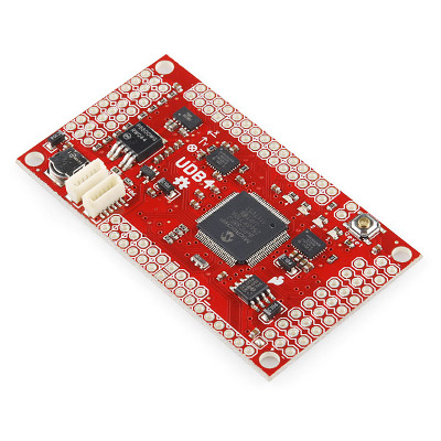
Here is the newest UDB board. In order for us to preserve a small form factor, we moved to a 4-layer PCB and a ll of the sensors were moved to the main board. We also added an EEPROM for additional flight data storage, more input and output PWM pins, another GPS connector to allow for a wider range of GPS units, and a more robust power system.
The new features do not stop there. The UDB now has the ability to target a pan and tilt camera at a specific 3D location, XBee communication is possible between your UDB and base station, flight plans can be written in a LOGO type programming language, and new features are rolling out all of the time. Be sure to check the Google code (project home) page for the most up-to-date information.
It is fun to watch Moore's Law in action (and even more fun to notice the increasing quality in our manufacturing process), but what really is interesting is what's going on under the hood, within the dsPIC CPU. Next, I will highlight some of the recent milestones in firmware development.
Firmware Development and Testing
The UAV development board is a 6 degree of freedom IMU (among other things). It takes signals from accelerometers and gyros, then computes it's attitude/orientation in 3D space. The DCM algorithm is the framework to accomplish this, but as it turns out, the calculations build up errors when the board is rotating continuously and quickly, similar to what you would see in an airplane barrel roll or an out of control death spiral.
To say it simply, the gyro computations get "dizzy" when spun quickly about an axis and then stopped. The reason why this happens is subtle. One of the primary developers has written a great report explaining this topic and other testing techniques he used to perfect the UDB code.
The report is somewhat dense if you don't have a math background, so bear with me hear while I try to digest some of it for you....
When the UDB powers on, you must hold the board stable and flat on a table while it undergoes a self calibration routine. Now, if the board is not completely flat (which it probably won't be), the initial conditions for the sensors will be slightly incorrect. This might not seem like much, but these errors end up propagating through the DCM calculations and feedback mechanisms during sustained high rates of rotation, resulting in the gyros becoming dizzy when the rotation finally slows. Higher rotational rates result in higher error accumulation rates, so you can imagine what would happen if your UAV went into a uncontrolled spin and these errors were not accounted for.
The error corrections don't stop there. The DCM calculations are actually linear approximations to the true non-linear representations of finite rotation math, which involve trigonometric functions. For slower rotational speeds, the linear approximation works fine, but start spinning fast and once again errors start building up. Higher order terms in the Taylor’s expansion for the trigonometric functions are introduced in the firmware to improve the accuracy.
Another correction was for gyro gain error. There is always some error between the actual gain of a rate gyro, and its nominal gain, typically up to 5%. The effects of these errors are only seen if you push the envelope in terms of rotation rate. For example, suppose you put your plane into a fast spin. Each time it goes around once, that introduces an error of 18 degrees. After 10 rotations, the error is a full 180 degrees. In other words, the estimated yaw attitude will be backwards!
The solution to the gyro gain problem is to automatically calibrate the gyros using other reference vectors during fast rotations. For example, during a spin, a magnetometer can be used to actually fine tune the calibration of the yaw gyro, and achieve zero calibration error. The UDB does not come with a magnetometer (for a few practical reasons), but it is very simple to connect one to the board. With the addition of the magnetometer, the UDB4 will have accurate computations in high rotations around any axis.
In order to make sure the magnetometer data was reporting the correct heading at the correct time, a measure of magnetometer latency was due. Instead of more traditional debugging techniques, the developers tested magnetometer latency by spinning the UDB on a record player and flashing a green status LED.
The latency was measured optically by flashing an LED as the UDB was spinning, much like a timing light can be used to adjust the timing of the ignition system of an automobile. A camera was used to take an extended exposure picture. First, the board was rotated slowly, two full revolutions. The reference pattern is shown above.
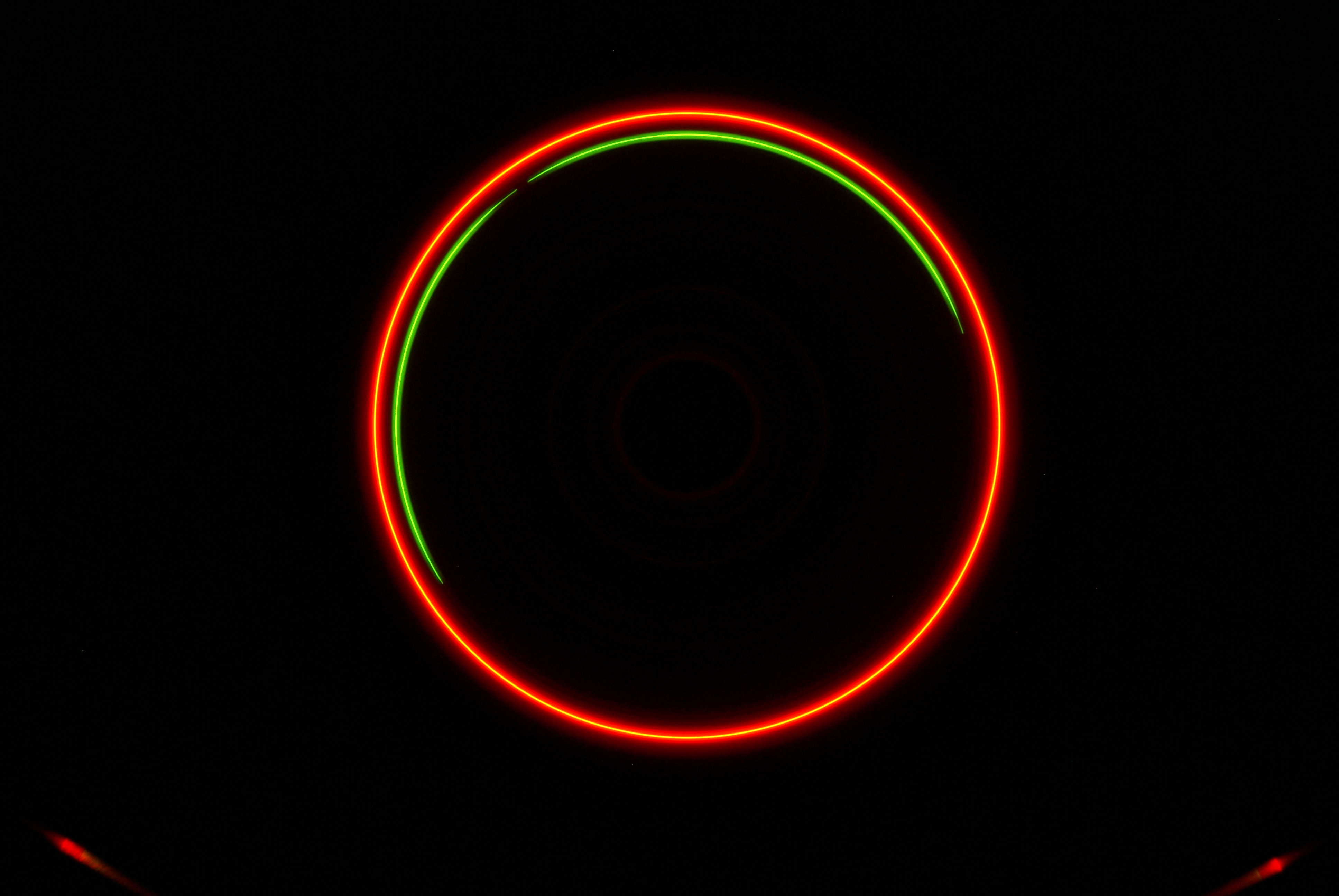
Next, the board was spun at 78 RPM and an extended exposure revealed that the latency was 0.085 seconds. It was a simple matter to adjust for the latency in the yaw drift compensation by taking a snapshot of the direction cosine matrix elements 0.085 seconds before the magnetometer reading became available. The image above shows an extended exposure of 10 revolutions after the latency compensation was implemented.

For the final "real-world" test, the UDB was put under spinning vertical dives to test the corrections. Turns out, the UDB can withstand sustained rotations up to 500 degrees per second in any orientation!
Overall, the UDB has been a great platform for research and development. It has allowed us to try out some really fun ideas and to expand its usefulness beyond its originally intended scope.
UPDATE: Matrix Pilot 3.2 has been released!


Mad cool, I've been wondering about this while designing a balancing robot.
What can i use instead of UDB4 now that it is retired?
I would recommend checking out the IMU section on the website. This will have the closest replacement boards for the UDB4. We are also working on a UDB5 board, but it's currently still in the development stage.
are there any equivalent boards to UDB4?
The UDB5 is on its way.
in some months or sooner, do you know maybe?
Awesome stuff! Looking forward to see what we can all do with this board
Really great information! Like Rogue, I've also been pondering these things while building my balancing robot. Although I doubt I'll need something as quite as sophisticated as UDB4--maybe just a 3 DOF accelerometer and a 1 DOF gyro--the "dizzyness" of the gyro does concern me.
Good luck with the Open House. Sounds like a real blast, wish I could attend.
I think the main problem of the DCM algorithm is the convergence ratio and the final error. Kalman algorith (IEKF) is complex to implement but it provides best results and accuracy.
http://www.ifrdesign.com/blog/2011/10/19/iekf-indirect-extendend-kalman-filter/
I want to buy a UAV Dev Board for my new rc airplane. But I don't know how to use it and how to connect it with my plane and my system and how to control it. Can anyone explain me how can I overcome my problems and buy one for my plane.