Enginursday: Fixing the ESP32 Thing Plus
In this Enginursday post, we talk about a fixing a problem the ESP32 Thing Plus had.

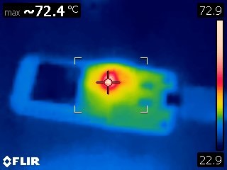
Recently, we released v20 of the ESP32 Thing Plus board. After releasing v10, we received some feedback that some boards weren’t able to upload code and the CP2102 was getting hot. It wasn’t a widespread problem, but it was a consistent problem for people that had the issue. When I was testing the board for example, I was able to upload code using both the USB ports on the computer, as well as my powered USB hub without issue. The USB power adapters didn’t cause any problems for me, except one, which helped figure out what was causing the problem.
The problem was a result of inrush current, specifically with switch mode power supplies. Switch mode power supplies have soared in popularity because they allow for smaller and more efficient power supplies, and can be found in nearly all electronics from phone chargers to desktop computers. They achieve this by increasing the AC frequency, which allows the transformers to be smaller by switching at a higher frequency, and by using a buck converter, they switch current through an inductor to charge a capacitor to a specific voltage.
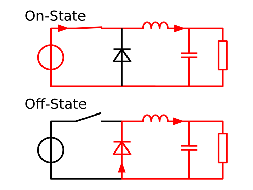
Image courtesy of CyrilB~commonswiki, CC BY-SA 3.0
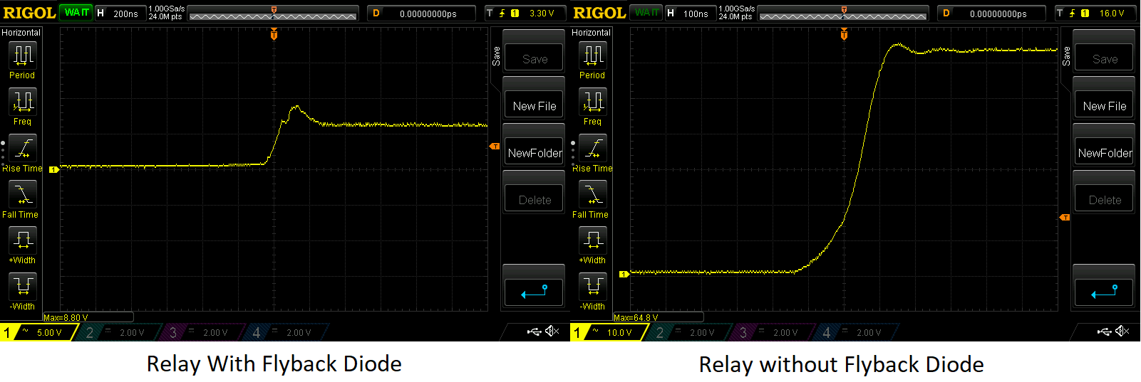
Without diving too much into the theory, inductors store energy in a magnetic field and resist the change in current. When an inductor sees a change in current, it tries to maintain that current by increasing the voltage until they run out of energy. This is why in our relay boards we use a diode across the coil to limit flyback voltage spikes, which could cause damage the switching transistor, as shown below.
Click the image for a closer look!
Finding the problem
Back to the ESP32 Thing Plus though. Now that I had a power supply that was able to replicate the problem some of the users were experiencing, I was able to connect my oscilloscope to the VBUS pin to see what was happening:
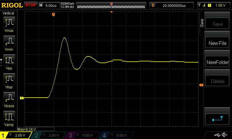
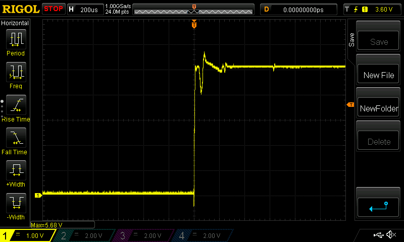
After seeing the peak voltage of 8.24V, I went back to the datasheet for the CP2102 and saw that the absolute maximum input voltage on VBUS was 5.8V. I performed the same test with a linear power supply, which still had a small overshoot, but at only 5.68V it was at least below the limit:
I suspected the problem was a result of inrush current and I turned my attention to the ceramic capacitors, which have a low equivalent series resistance (which you can learn more about here). Having a small ESR value is good because it allows the capacitor to respond quickly to voltage ripple, but when it first charges up it can cause a large initial spike in current. At first it might be tempting to just remove capacitors, but as the waveform below shows, without capacitors the ripple from the switching power supply would generate too much high frequency noise on the VBUS rail.
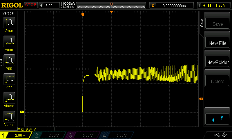
Without the capacitors though, we can see that the initial voltage spike is gone. Knowing that the low ESR capacitors are causing a problem but that removing capacitors creates a new problem, I needed to find the middle ground, which can done by adding intentionally adding ESR to capacitors with a small value resistor in series with the capacitor. Another problem, however, is that because of where the capacitors are placed, adding a series resistor to the capacitors would add a lot of time reworking the board to move traces and vias.
Before investing the time moving traces around, there was more room available around the CP2102, which gave me another idea. After checking with the datasheet again to see that the input current for the CP2102 was around 20mA during normal operation, I wanted to see if adding a resistor in series between VBUS and the supply pins of the IC could fix the problem. After using my decade resistance box, I settled on value of 10 ohms, which produced the following result:
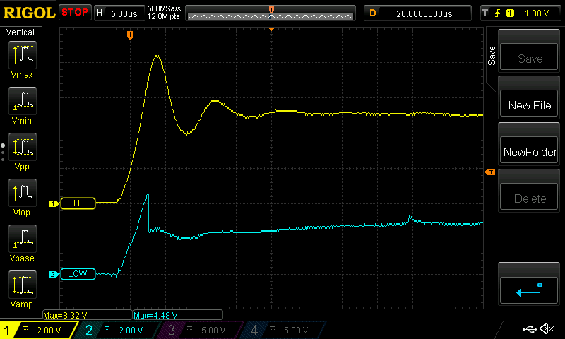
The yellow trace is on the high side of the resistor connected to VBUS, and the blue trace is connected to the low side of the resistor connected to the supply pins of the CP2102. As you can see, the spike still makes it through the resistor, but instead of reaching a peak voltage of 8.3V it only peaks at 4.48V. The time scale of 5us/div makes it look like the CP2102 drops back down to around 3V and stays there, but the actual voltage drop with this supply is around 200mV and gets to a steady state voltage within 200us.
As engineers, the goal is to have a test procedure that can thoroughly test your design to identify limits and fix them before it lands in the hands of customers. But just like when the Raspberry Pi added USB-C, mistakes can still happen when you use components for the first time.


I have 2 v1 boards that my son used for a school engineering project. Never had any issues like this. However, good article and information so if we run into this problem we know whats going on. ( he was one of the winners with his cellphone controlled water delivery system) :)
Ok, good post, but the main question remains unanswered:
If I have one of these boards, what do I do to resolve this problem?
Use it for target practice? Return it? Attempt a repair with my shaky hands and risk both destroying the board and voiding the warranty?
Thanks!
Jim, please consider filing a return ticket with the information we ask for and our support team will take care of your board and offer a proper solution: https://www.sparkfun.com/returns
Pololu did a decent writeup about this sort of issue quite a while back, and Linear put out a great app note about the same sort of thing.
Short version: bodge a cheap, low-grade electrolytic in parallel with the ceramic cap whose inrush is causing the overshoot. The high ESR gets you a nicely damped circuit without having to run the load current through a resistor. Be very cautious about this if you're powering projects with individual leads instead of a two-conductor cable; the larger loop area brings a lot more inductance to the party and requires more damping.
Cp2102 is old.. i use the co2104 for my stuff. Also there is a newer one out. These aren't recommended for new designs. I used to use the cp2102 all the time and never had an issue.
Very interesting! I fried three things plus and figured out that the CP2102 was the problem. I ordered some and resoldered two successfully, one board is dead even with the new CP2102. Will there be a way to fix this at home somehow? Cheers
The one that still isn't working, what version is the board? The version number is on the bottom of the board by the USB connector. The best at home fix would be to replace the CP2102 as you have with the other boards. What's the behavior of that board when you plug it into USB? Is it just not being recognized by the computer, or is the new CP2102 still getting hot?
Hi Alex, all three are V10. I just saw that actually two of them are dead. Some of the traces underneath the CP2102 came off on the two dead ones so I think thats the problem. On power the charge led comes on for a second but they are not recognized by the PC. I used the same temperature (hot air rework station) when working on all three of them so maybe two of them where more fragile due to the previous heat. The one that got the new chip and three other ones I own work flawlessly. Cheers, Andreas