
Happy National Trivia day, ya nerds! In honor of this very special day dedicated to the great institution of trivia, we have built a four-person game buzzer interface to bring some game show action into your very own living room! The year 2017 has finally arrived, and we all want to do better this year. Why not start by breathing some new life into your game night? An extra competitive edge is guaranteed!
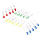
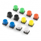
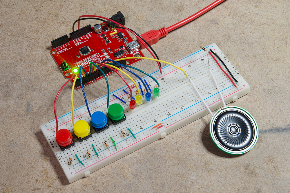
This DIY game buzzer uses the SparkFun RedBoard connected to four momentary push buttons---each representing a player or team: red, yellow, green and blue. There is an LED for each team in its corresponding color and one speaker. When your game night host asks a question, each team has the opportunity to buzz in. When the first team pushes its button, the corresponding LED will light up for five seconds and a unique tone will play on the speaker for one second. There will also be an indication on the serial monitor as to which team succeeded in buzzing in first. Once the first team manages to press its button, the rest of the players or teams become "locked out" for five seconds so there is no confusion regarding who hit the button first!

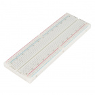
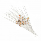
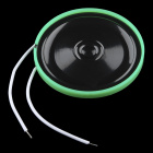
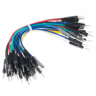
This project is simple and fun to make and use. To get started, you will need to gather the following supplies:


Use the following diagram to build your circuit. I set up the example as a four-player/team console with each color representing a player/team. However, you can increase or reduce the number of buttons and LEDs to suit your game night crew’s needs.
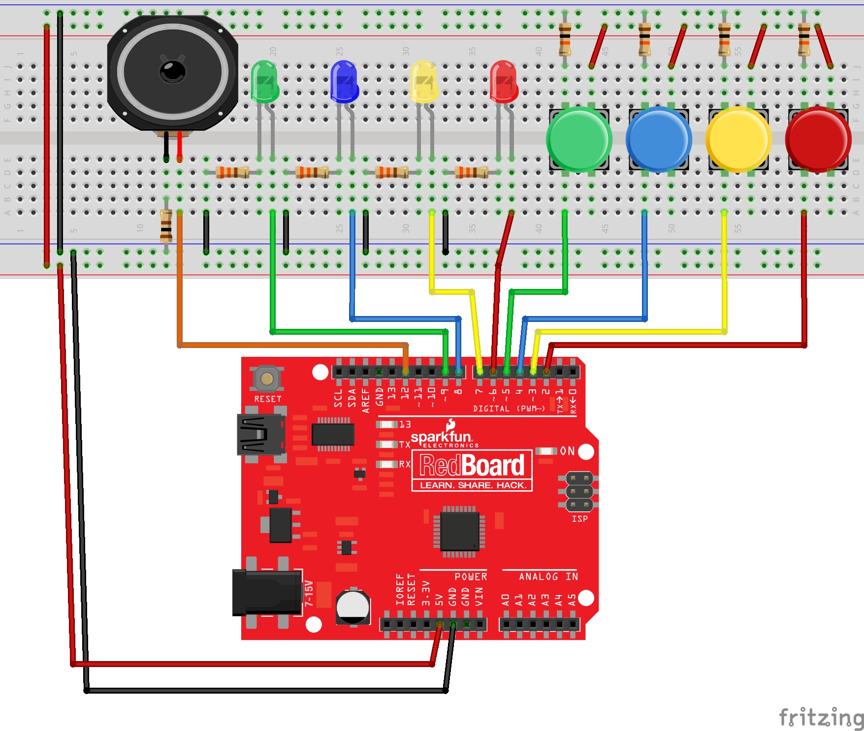
Having a hard time seeing the circuit? Click on the wiring diagram for a closer look.
Finally, copy and paste the following code into your Arduino IDE and upload it to your board.
/******************************************************************************
trivia.ino

Melissa Felderman @ SparkFun Electronics
Jan 3, 2017

Description:
game buzzer sketch for four users
******************************************************************************/

//assign buttons to pin
int redBut = 2;
int yelBut = 3;
int bluBut = 4;
int greBut = 5;

//assign LED to pins
int redLED = 6;
int yelLED = 7;
int bluLED = 8;
int greLED = 9;

//initialize button state to 0
int redButState = 0;
int yelButState = 0;
int bluButState = 0;
int greButState = 0;

//locked out state variables
boolean pause = false;
int secs = 5000;

//assign speaker pin
int sound = 12;
int soundSecs = 1000;

void setup() {
  //begin serial communication
  Serial.begin(9600);

  //initialize button pins to input
  pinMode(redBut, INPUT);
  pinMode(yelBut, INPUT);
  pinMode(bluBut, INPUT);
  pinMode(greBut, INPUT);

  //initialize LEDs to output
  pinMode(redLED, OUTPUT);
  pinMode(yelLED, OUTPUT);
  pinMode(bluLED, OUTPUT);
  pinMode(greLED, OUTPUT);

  //initilize LEDs to Off
  digitalWrite(redLED, LOW);
  digitalWrite(yelLED, LOW);
  digitalWrite(bluLED, LOW);
  digitalWrite(greLED, LOW);


}

void loop() {
  if (pause == false) { //only works when buzzers are unlocked

    //read button states
    redButState = digitalRead(redBut);
    yelButState = digitalRead(yelBut);
    bluButState = digitalRead(bluBut);
    greButState = digitalRead(greBut);

    //repeat the following code block for each button included. make sure to update the variable names when copy and pasting this block.
    if (redButState == 1) { //if red button is pushed
      pause == true; //puts program into lock mode so other players cannot buzz in
      digitalWrite(redLED, HIGH); //lights up corresponding LED
      tone(sound, 900, soundSecs); //plays team tone for one second
      Serial.println("TEAM RED"); //Serial indication of first team to press buzzer
      delay(secs); // five second delay - enforces lockout for other players
      digitalWrite(redLED, LOW); //turn LED off
      pause == false; //turn off lockout mode

    }
    if (yelButState == 1) {
      pause == true;
      digitalWrite(yelLED, HIGH);
      tone(sound, 700, soundSecs);
      Serial.println("TEAM YELLOW");
      delay(secs);
      digitalWrite(yelLED, LOW);
      pause == false;

    }
    if (bluButState == 1){
      pause == true;
      digitalWrite(bluLED, HIGH);
      tone(sound, 500, soundSecs);
      Serial.println("TEAM BLUE");
      delay(secs);
      digitalWrite(bluLED, LOW);
      pause == false;

    }
    if (greButState == 1){
      pause == true;
      digitalWrite(greLED, HIGH);
      tone(sound, 300, soundSecs);
      Serial.println("TEAM GREEN");
      delay(secs);
      digitalWrite(greLED, LOW);
      pause == false;

    }
  }

}
...And just like that, you have your very own game buzzer. With this little project, game night is entirely transformed!
Feel free to take your game play off the breadboard by fabricating individual buzzers for each player/team!
Have you made a trivia-related project? Share your trivia and game night projects with us on Twitter, facebook, and in the Comments below!


I think today's post is a great example of the value of open source and community collaboration. I applaud SparkFun for receiving criticism positively. That is not an easy thing to do.
I have a project and this looks like it could be ideal for it. Is there a way to link the Output LED to a relay to trigger a bigger 12V lamp? Would it also be able to send sound output to an amp so sounds can be much louder? Can the sounds for the different teams be wav files to make it more fun?
Hi there, it sounds like you are looking for technical assistance. Please use the link in the banner above, to get started with posting a topic in our forums. Our technical support team will do their best to assist you.
Can this be done for 8 buzzers? Thank you
Absolutely!
Thanks for the quick answer. I'm going to attempt this with someone who knows more than me about it but wanted to do some research on my own. Could the 8 buttons be done on this one board or would I need 2? Thanks
Yes you definitely can. Just add 4 more buttons and corresponding LEDs with the same wiring, having each one go to it's own digital pin. Then imitate the code for the first 4 buttons and LEDs for the second 4, but update the values for the pins and variables like so:
//assign buttons to pin int redBut = 2; int yelBut = 3; int bluBut = 4; int greBut = 5; int newbutton1 = 10; int newbutton2 = 11; int newbutton3 = 12; int newbutton4 = 13;
//assign LED to pins int redLED = 6; int yelLED = 7; int bluLED = 8; int greLED = 9; int newLED1 = 14; //this is pin A0 being used digitally int newLED2 = 15; //pin A1 being used digitally int newLED3 = 16; //pin A2 being used digitally int newLED4 = 17; //pin A3 being used digitally
and so on...
You know... idea hits - Sparkfun already has a 4 button w/led display and buzzer. :) I bet it would be no problem at all to hack the game buzzer code in to the Simon-Says, like when I made it do Magic. See https://www.sparkfun.com/news/1206
:)
This really needs to use the big buttons, not those little things. Ya it's not breadboard friendly, but would be much cooler! https://www.sparkfun.com/products/11274
If one were follow the fritzing diagram exactly, the red LED would not light up. The jumper connecting the resistor to ground is in the wrong place.
Good eye! Thank you for catching our mistake. We have updated the fritzing diagram in the post.
Is it just me, or does it look like blue buzzes in first in the GIF, even though green is indicated as the first?
The code sample includes
which does not have any effect (should only have one equals sign). You got away with it because the check of pause has no meaning; it will always be false at the start of loop, since delay() prevents the Arduino default code from executing loop() again during the period when pause is true.
Yep pause code is irrelevant and can be cut completely (if statement check too) from the program and it would work the same :-)
Also, if you want to guarantee that only one of the button codes was run each loop around, the button checks should be inside if and else ifs instead of all independent ifs.
If else if code is great for things you know are mutually exclusive, if you found one to be true you can skip checking all the rest and guarantee only one is run ;-)