IoTuesday: WiFi Maximizer with DIY Yagi-Uda Antenna
I create a Yagi antenna out of Popsicle sticks and paperclips and use it to measure connection strength (RSSI) to WiFi access points.

In a previous IoTuesday post, I gave examples of makeshift antennas you could build at home. I wanted to make my own and create a kind of "WiFi Divining Rod." I used a SparkFun ESP8266 Thing Dev board and OLED attached to the antenna, which would connect to a WiFi access point and display the received signal strength indication (RSSI) on the OLED. I could then change the antenna's position and orientation to determine the best connection to the access point.
I liked the design of the Yagi-Uda antenna, as they are simple to build and seem to be fairly forgiving (mine didn't turn out particularly straight). I followed Biotele's Instructable to create an antenna out of Popsicle sticks, paper clips and glue.
The Instructable shows a 15-element Yagi-Uda, which theoretically gets you about a 15 dBi gain (see here to learn more about decibel reference values). I needed something that was smaller and handheld. One nice thing about Yagi-Uda antennas is that you can just trim elements off the end and trade gain/beamwidth for antenna length (more or less -- it does change the beam pattern).
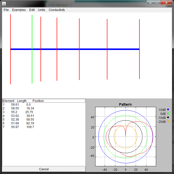
You can download the AB9IL Java app that Biotele used in their article to view the beam pattern of a Yagi-Uda. Here, I entered the same dimensions of Biotele's antenna and then removed the last eight "director" elements. This, in theory, would get me less gain (around 10 dBi) with a slightly wider beamwidth.
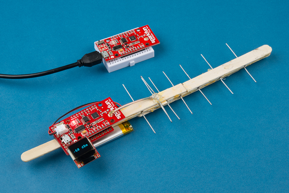
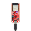
After building the antenna, I attached a Thing Dev board (using some foam tape) and an OLED to the end of the antenna's backbone, which kept the U.FL cable as close as possible to the antenna's driven element. I wrote a quick Arduino sketch that simply reported the RSSI of the WiFi connection on the OLED.
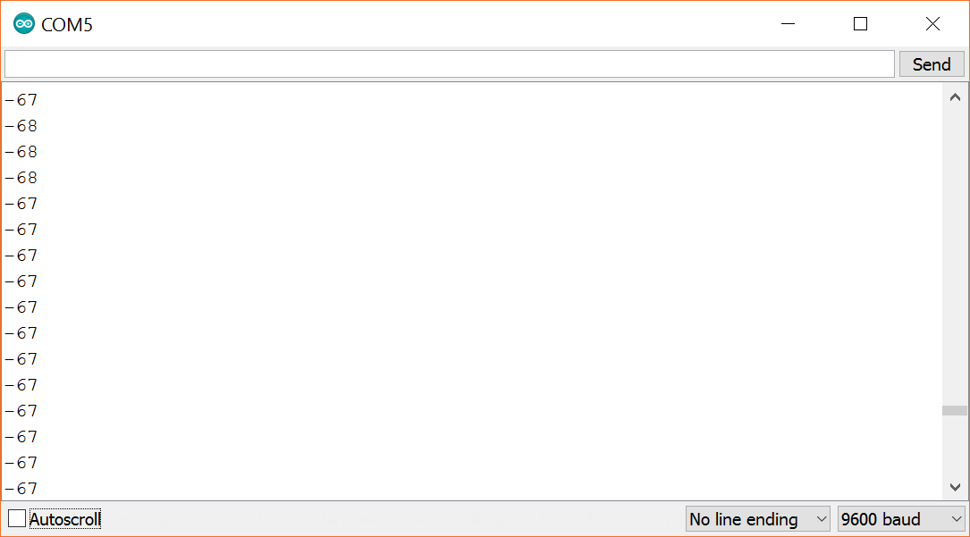
I performed some basic tests to see how the custom Yagi-Uda compared against the Thing Dev board's PCB antenna, and I was pleasantly surprised. I went out to the front of the SparkFun building (by our beehive -- about 75 meters away from the building) and held up an unmodified Thing Dev board. I changed its orientation to find the highest RSSI, and the best receive strength I could get was around -67 dBm.
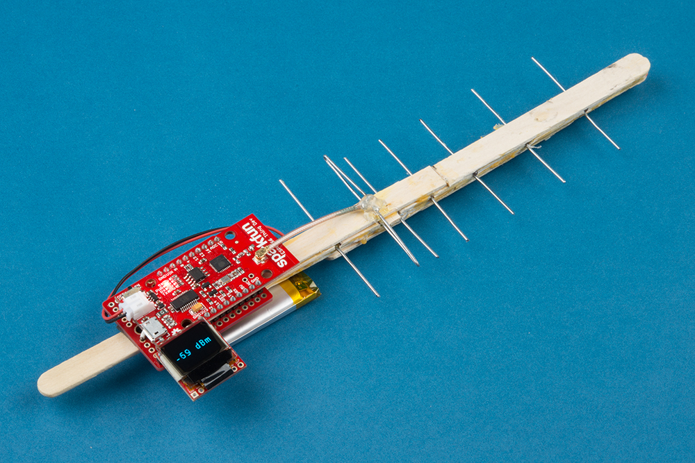
I tested the RSSI again with the "WiFi Maximizer" (best name I could come up with for a Thing Dev board taped to a makeshift Yagi-Uda antenna), and found that that I could get around -61 dBm (same position, not necessarily the same orientation).

With my completely unscientific testing, I figured I was getting around 6 dB of gain over the onboard PCB antenna, which isn't bad considering the backbone was crooked, the elements weren't exactly lined up, and there was no impedance matching whatsoever (among a whole host of other issues, I'm sure).
I have not performed a line-of-sight distance test, but I'm willing to bet I would be able to connect to our building's WiFi at a farther range than with just the PCB antenna. If you're looking for a quick (and very cheap) way to boost your Internet of Things (IoT) device's connection, then this makeshift antenna is one good way. This might work well, for instance, in a classroom setting where students need to build a device to take measurements at a location where the nearest WiFi access point is a kilometer away.
Additionally, the directional nature of the Yagi-Uda means that you could potentially use this setup in a small-scale transmitter hunting game (assuming the transmitter was broadcasting a 2.4 GHz WiFi signal).
What other antenna tricks can you offer to help boost the range of IoT devices (specifically, something in the 2.4 GHz or 5 GHz bands) without spending a fortune?


Pretty cool. You could make a stepper motor turntable to hold your signal strength device, then step it around 360º, plotting/logging the signal strength as you go. The resulting plot is the radiation pattern of your antenna. You would want the pivot point to be right underneath the "driven element", to prevent measurement errors due to varying distance between the source and yagi antenna.You can also experiment with the polarization of the receiving antenna, to determine the polarization of your signal source antenna on The Thing. You can pick up or lose a good many dB by being "on axis" or "off axis".
Nice! I like it. Then I could compare the pattern to the theoretical pattern. Experimenting with the Yagi-Uda's polarization proved to be tricky, since, I believe, most of the antennas on our access points in the office are circularly polarized.
Don't mean to be a debby downer, but IIRC, the radiation pattern of a Yagi changes with it's input matching, because the current and voltage phase on the director element has to be in the 'right place' to get all the elements to work together. There's delta and gamma matching networks to get the job done, but they aren't always easy to do at microwave frequencies.However, one idea I'd want to try is create a delta match, by taking solid shielded wires direct from the Thing's feedpoint and ground, and fanning them out to the (single wire, uncut) directed element. You'd then just play with the connection points to optimize the signal gain.
Another really simple idea I'd have loved to see if just looping the coax a few times (3 or so) would significantly improve things. That makes a choke, which can help balance the feedline. I know chokes attenuate alot on microwave frequencies, but it'd be easy enough to try out to see if you could squeeze out a few more dB gain.
Nice work. I just google and saw that you can design Yagi antenna on PCB. That would make a nice looking dev board.