
Terrible clickbait titles aside, I wanted to improve on a project from a few weeks ago. Nick Poole gave me the idea of automating the DIY Yagi-Uda antenna/divining rod I had put together in order to find the orientation of the maximum WiFi signal strength.
The execution was straightforward: mount the antenna and ESP8266 Thing Dev Board onto a pan/tilt bracket with some servos. The ESP8266 code was updated to connect to a WiFi access point (AP) and begin sweeping up and down (about 70°) and left to right (about 180°). At 5° increments, the ESP8266 would take an RSSI reading and remember the yaw and pitch settings of the highest RSSI. After sweeping, the antenna automatically returns to the position with the best RSSI.
Here's a video of it in action:
There are, of course, a number of problems with this whole setup:
- The polarization (roll) of the antenna is not taken into consideration. It would require another servo to test vertical and horizontal orientations.
- If the antenna were moved, it would obviously require another maximizer sweep.
- If you stand in front of the antenna, place your hand near it, or put any sort of object in its line of sight. You change the multipath propagation of the radio waves, which can mess up the sweep tests or change where the best signal strength might be.
- I'm still relying on a poorly made DIY antenna. A professionally made directional antenna should, in theory, perform a lot better than my warped popsicle stick and paperclip monstrosity.
- Because the sweep arc is limited, the best connection might be behind the antenna.
Here's a shot of the rig post-maximization:
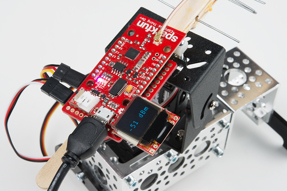
The OLED display shows an updated RSSI to give you an idea of the connection strength even after the sweep is complete. If you think the given dBm might be unacceptable, then you may want to move the rig and test another spot, especially if you are indoors and multipath is an issue.
If you are interested in trying out the WiFi Auto Maximizer for yourself, you can find the pin connections and code here.
This setup could be useful for performing a very basic characterization of antennas (as per 71784's suggestion) if you are outdoors and have line of sight to an access point. By sweeping through the different angles, you could develop very simple and limited azimuth and elevation plots. It would not be very accurate, but it could still be useful for those of us without access to an anechoic chamber.
If I wanted to buy an inexpensive 2.4 GHz directional antenna (in lieu of DIY) to test with this rig, what would you recommend? Share your thoughts and suggestions in the comments below.


What a Great project! Can you share me the connection diagram, I want to do it all by myself.
Very nice.
Which mount/stand/parts did you mount the pan/tilt kit on? Thanks
If this trick help increase my wifi speed i will be the most happiest person.
I like the idea of using it for solar tracking! I've seen this done on larger panels, but it could work for smaller ones, too. You are correct: WiFi has multiple peaks in multipath environments (e.g. indoors).
Is there a parts list for the ServoCity pan/tilt components? Thanks.
The pan/tilt is this kit, an HS-422 servo, and a sub-micro servo.
Hey Shawn,
Good article. I almost commented after your first antenna effort, but didn't want to seem overly critical as the wiki you were following had some good general ideas. I would like to second #394180's comments below about the ARRL books though. Being a long-time ham, I have learned a lot about antennas from reading through the ARRL Handbook (which is republished every year, so stories and information varies).
Biota's original instructable has a few minor issues that are addressed in fairly good depth in the instructable's comments. The higher yield comments concern using copper wire instead of paperclips, and using an regular dipole instead of the folded dipole as the driven element. Lot's of good discussion on his site, but these are two things that will yield a better antenna and more consistent construction results.
The ARRL books take you through the math with some fairly simplified formulas, but there is also a lot of antenna lore and rules-of-thumb that you can get out of it that are a big help. In general though, putting ANY kind of reasonably matched external antenna is going to greatly improve your wifi connectivity. I have little experience building circularly polarized antennas, but I have read some interesting things about them in the ARRL Handbook and agree that that will probably have the best results in this case.
Thanks for the continuing good thoughts.
You don't need another servo to handle polarization, you need a circularly polarized antenna. Those can handle either vertical or horizontal linear polarization. They only have a problem when used with another circularly polarized antenna that has the opposite polarization, i.e., left hand vs. right hand polarization. In that case you could make an array of 2 circularly polarized antennas with opposite polarizations and have a switching element (diode, relay, etc.) that is driven by a single GPIO output. You may want to consider antennas used for amateur satellite stations. They have to handle random polarization changes caused by Faraday rotation, as well as low signal levels.
I would never use anything but DIY antennas for this. They are so easy to build and use so little material that it's not worth it buying a commercial model. I was once able to extend the range of a key fob transmitter from 5 to 125 feet with a homemade replacement antenna. In this case, though, I put the new antenna on the base station, not the fob. Instead of a single wire, I had a vertical groundplane antenna with the impedance matched to the transmitter (hint - in commercial gear it's always 50 or 75 ohms) simply by bending the groundplane wires. So keep in mind that the base station antenna might be a more fruitful target for replacement.
Finally, the ARRL has lots of books with data for easy to make DIY antennas from shortwave to microwave.
The old T(ransmitter)-Hunting trick for dealing with unknown polarization is simply to put your yagi at a 45-degree angle. You'd have some attenuation compared to guessing correctly, but it was a good compromise. Also helped with mast-height issues above the vehicle compared to vertical orientation.
Good tips about ARRL and placing the DIY antenna on the base station or access point. It seems that most of our access points at work are circularly polarized, so it doesn't matter how I orient the Yagi-Uda. However, most home access points have the rubber duck-style antennas, which I believe are vertically polarized (depending on their orientation).