Enginursday: Steps Toward an Inverted Pendulum Robot
A classic control systems challenge is building an inverted pendulum robot. Today we'll discuss the theory behind the project.

A classic control systems challenge is building an inverted pendulum robot. Today we'll discuss the theory behind the project along with some practical tips on building one yourself!

Mechanics
The actual chassis of your robot must be carefully designed if you're going to have any hope of getting it to balance.
The Structure
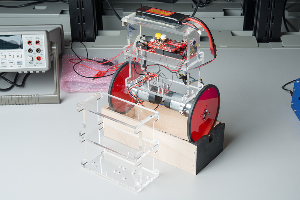
First, let's talk about the structure of a balancing robot. My experience with several attempts at building one has taught me one very important thing: rigidity matters. Your robot needs to be stiff so that it doesn't flex much as the wheels try to balance it. If it can flex too much, you'll get a whip-crack-like effect where a wave traveling up the structure causes the top to "crack" and throw the weight hard in the direction where you want it to go, causing a serious amount of overshoot.
The next point is counter-intuitive. You want the robot to be tall, with as much weight located as far from the axis of the wheels as possible. The taller the better, and the higher the center of gravity, the better. To understand why this is so, a simple experiment can be done. Grab a broom, or a mop, or something similar. Try balancing it vertically on your palm with the bristle end up. Pretty easy, right? Now try it bristle end down. Much harder, isn't it? The principle is no different.
The Motors
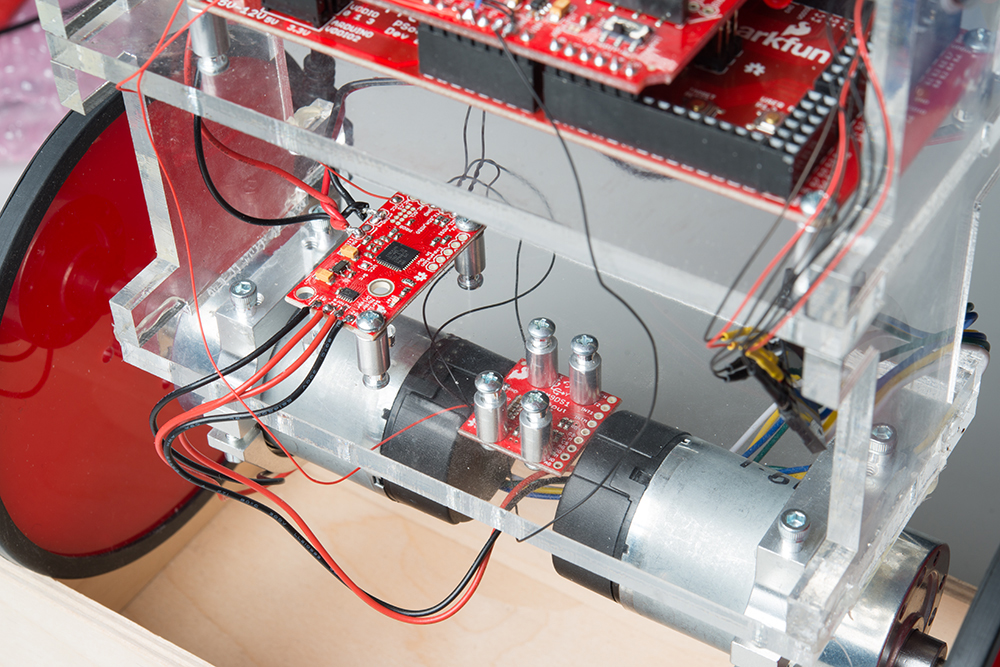
You need fast motors to make this work. Our fastest Actobotics gear motor is just fast enough when run on a 7.4V two-cell LiPo battery to keep my robot upright, but they aren't fast enough to recover from a good shove.
You also want motors with minimal backlash. Backlash is the amount that a motor has to turn before the wheel starts to turn in the direction the motor is trying to drive it. Backlash is caused by slop in the gearbox, and it causes a real problem in a balancing robot. You can prevent the issue by using a motor with a planetary gearbox, which typically has lower backlash than a traditional gearbox.
The Wheels
In general, the bigger the better. There's a limit to this, of course, because a larger wheel requires more torque to turn, and you have a finite amount of torque to work with. Still, it makes good sense to use larger wheels rather than smaller ones. I used our 5" precision disc wheels, and they're terrific.
Electronics
The electronics can be surprisingly simple.
Sensors
Believe it or not, there are options here. The overall goal is to measure the angle of the robot and run the wheels in opposition to any motion such that the bottom of the robot is moved under the top of the robot as the top tips. There are at least two ways to do this: via an inertial measurement unit (IMU) or by measuring the distance between a fixed point on the robot's chassis and the ground.
Distance-Based Measurement
By using a sensor such as an ultrasonic range finder, LIDAR or infrared time-of-flight sensor, one can determine the tip in the robot's chassis with some simple trigonometry, if one knows the ideal distance from the sensor to the ground. Of course, this has its drawbacks, chiefly that rough or angled surfaces will cause the sensor to have trouble getting an accurate measurement. However, if your only goal is to get some experience with the basic concept, this can be a very attractive method.
IMU-Based Measurement
An IMU is a sensor containing two or more motion sensors. For our purposes, we need a gyroscope and an accelerometer. A gyroscope measures rotation around an axis, and an accelerometer measures acceleration (in this case, we're concerned with acceleration due to gravity). The reason we need both types of sensor is due to the shortcomings of each type. A gyroscope tends to drift over time, causing spurious readings of motion. An accelerometer is sensitive not only to acceleration caused by gravity but also acceleration caused by motion. Together, however, these sensors can have their flaws compensated out, thus providing an accurate measurement of angle with respect to the gravity vector.
I used an LSM9DS1 IMU board for my robot. I like the I2C communication, as it's more accurate than reading an analog sensor and requires fewer pins than SPI.
One further note on the topic: it doesn't really matter where your IMU is mounted. A lot of people go to lengths to mount the IMU as close to the wheel axis as possible, but that's not really necessary, especially if you heeded my advice and made your robot's chassis nice and rigid.
Computing
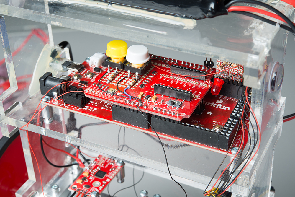
It turns out that the math required to keep a balancing robot upright isn't terribly awful, and an Arduino-class processor can handle it. I've had some success using our SAMD21 Mini Breakout and our FreeSoC2, but if you look around on the web you can find examples using Arduino Uno or similar boards.
Motor Control
You'll obviously need a motor controller. Some kind of H-bridge-type driver is necessary, so the motor can be driven forward or backward. I used our Serial Controlled Motor Driver because it can be controlled over I2C, minimizing the number of connections needed.
Battery
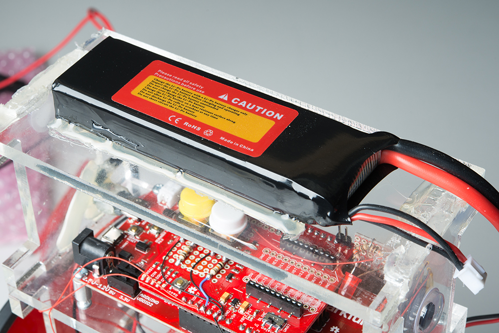
You want a big battery because it can then function as ballast to raise the center of gravity. I used our 7.4V two-cell LiPo battery mounted at the highest point of the chassis. An important caveat here: make sure you monitor the voltage of the battery! I ruined a couple of these batteries by over-discharging them before I added a voltage monitor circuit and warning LED to my robot.
Software
The heart of the robot is, of course, the software that does the calculations to keep it upright. We're going to assume that you've decided on an IMU-based approach.
Kalman Filter Sensor Fusion
As mentioned above, we have two types of sensors on the robot (even though they are colocated in the same physical package): a MEMS gyroscope and a MEMS accelerometer. By clever math, these two sensors' outputs can be synthesized into a single value: the angle between vertical and the current rotational position of the robot. The means for this synthesis is an operation called Kalman filtering. In a nutshell, a Kalman filter uses a probabilistic model of where the robot was a moment ago combined with the input of the sensors to create a probabilistic output for where the robot is now. If you want to read more on how a Kalman filter works, I suggest this page for having a solid explanation clearly demonstrated in pictures. The actual math of the Kalman filter is beyond the scope of this article.
PID Motor Control
Thanks to the magic of the Kalman filter, we now have a good model of where our robot is in terms of angle from normal. We need to then calculate what motor response we need in order to return it to normal (i.e., upright). To do this, we use what is called a PID loop. PID stands for Proportional Integral Derivative, for the three components which make up the overall directive to our motor. The proportional portion is some constant times the error currently present in the system. To this, we add our integral portion, a constant times the sum of the error over the history of the system, and our derivative portion, which is a constant times the current rate of change of the system. By tuning these three constants, we can create a system that responds to perturbations in a controlled and stable manner. Tuning a PID loop is beyond the scope of this article.
The Result
Here's a video of my robot, teetering along.
I suspect that a great deal of the instability of the robot is due to motor backlash, as it allows a great deal of time (relatively) to elapse between the instigation of a corrective action and the actual corrective motion beginning. I'd like to try the robot with planetary gearbox motors to see if that removes some of the jittering motion, but that's outside of one of my initial constraints, which was that the robot should use only parts sold by SparkFun. I'm not sure why it does the thing where it suddenly takes off in one direction and then falls over. If you have any ideas, I'd be glad to hear them!
What do you think? Have you ever tried to build a robot like this? What was your experience? Would you like us to provide a more formal example, with sample code? Leave us a comment below!


I'll often take off in one direction and fall over as well. I don't know why either.
Since all of my self-balancing robots, http://twopotatoe.net, use wheel encoders, I normally can’t offer much useful advice for your robot. Nevertheless, I have a few comments:
You are right about keeping the weight high. However, with an effective algorithm the weight can be kept quite low. Witness FivePotatoe: https://youtu.be/9pQcHJDpBWg6. As you can see, it also allows self-righting which is kind of neat. SixPototoe—https://youtu.be/ShRu4HaDT_M—also has this characteristic.
Most balancing robots—but not mine!—use a PID algorithm, which can often be made to work quite well. However, if you follow general control theory practices, the “I” should not be needed. But yet, most people need it to get the robot to stay up at all. Why is this? I think it is the speed of the robot that hasn’t been added in to the calculations. Essentially the “I” should be removed and the speed of the wheels should be substituted. This is not easy but doable. I think this is why your robot is falling over. Nevertheless, some PID adjustments could fix it as well.
As for the algorithm rate, higher would seem to be better. However, anything much over 100HZ is probably unnecessary since the low pass filter in the IMU makes a higher rate mostly ineffective. In fact, rates as low as 20HZ can work quite well.
Motor size is always a problem. If the motors aren’t providing enough power, just up the voltage! Anyway, you work at Sparkfun so replacing motors shouldn’t be a burden.
The higher the feedback loop rate, the higher the noise sensed by your IMU. The loop rate should only be high enough to achieve control. Backlash can be a problem too. I use stepper motors with Sparkfun's LSM6DS3 breakout. Loop rate is 100hz. Results not too bad: https://www.youtube.com/watch?v=QHb9eYAyGJc
The cool kids are calling “backlash” “lost motion” these days.
Looks like your prop gain is way too hot. You may want to throw in a low-pass filter too: that type of gearbox combined with the bad inertia match probably gives you all kind of ugly resonances. Derivative terms tend to hate noise in the feedback as well, so you might want to switch it to a PI loop…
Feedback needs to be more like 400hz. By applying a highpass filter to the PID controller, you can get it to defeat the oscillations caused by mechanical lag.
Good work, just looks like PID tuning. How fast is your control loop running? (And is your code executing at exactly that frequency?) PID is finicky, because all of your gains are associated with a fixed time-delta (if the actual delta is too jittery, then robot looks like they just had a few shots of espresso).
Sharing my robot too! http://ohmwardbond.blogspot.com/2014/12/self-balancing-robot.html?m=1
The PID is running at 100Hz, but the actual execution time is about 1.5ms, so the timing ought to be quite repeatable. I'll look into it, though.
Cool experiment.
After watching the video a few things come to mind about the speeding off and falling over. Assuming the speeding off is due to an error correction above some threshold. Could it be any of the following?