Fan-Out Capability of the APA102C
You'd normally run them in series. But can you run them in parallel?

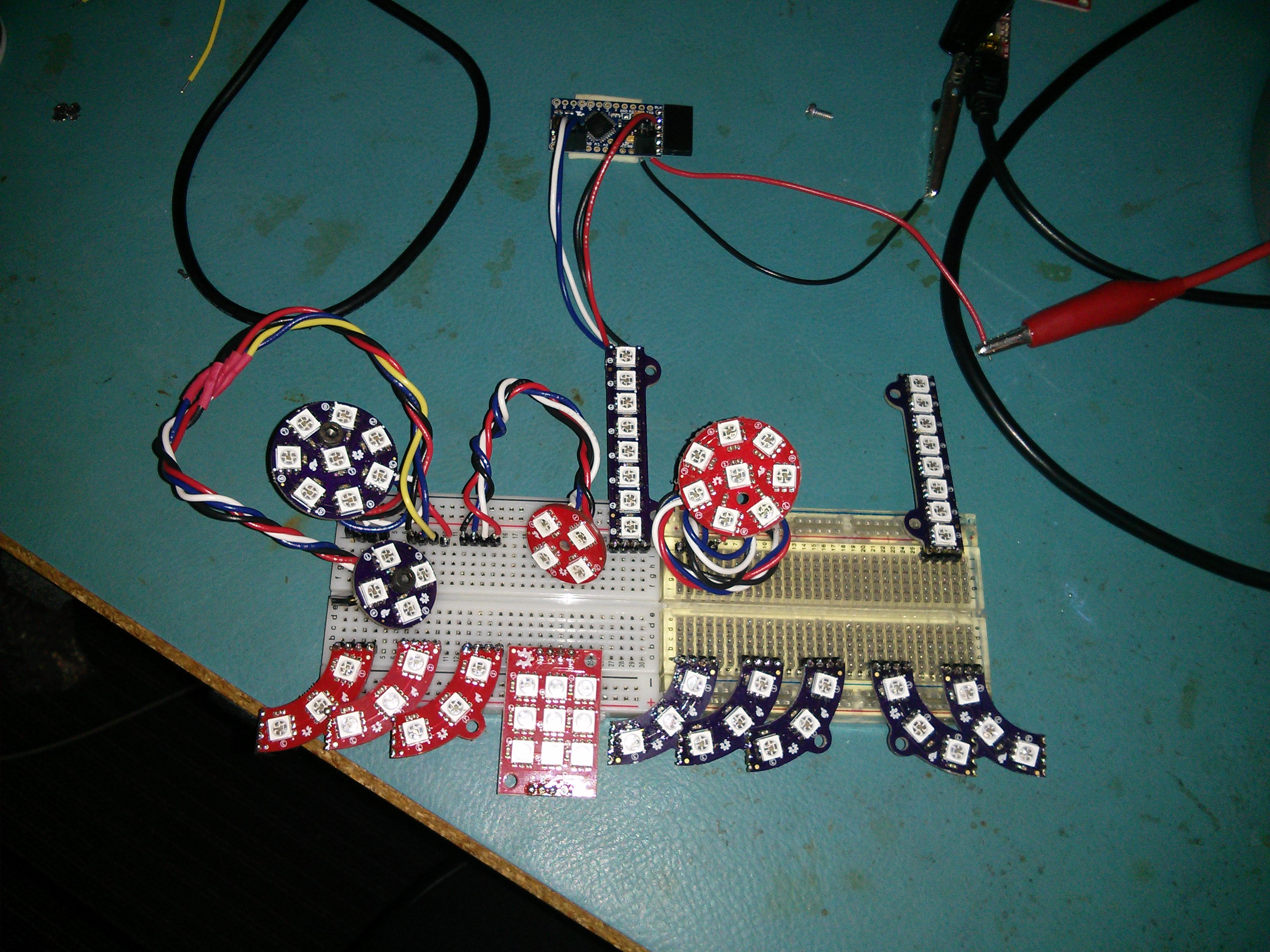
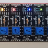
Our victims for the day
While playing with APA102C addressable LEDs, I found myself thinking about the various hypothetical lengths of various hypothetical strings of them and how DC has to be carried down to the end of the string, and how you've got some amount of propagation delay for the logic that runs through every LED.... And I started wondering about the viability of running the parts in parallel with regard to the logic.
"But Pete, why would you do that? The whole point behind them is to have control of every pixel with a minimum of wiring." Well, this would be applicable in only certain sorts of installations, I'll grant you that. I mean, the DC benefits are clear: what would have been a longer, daisy-chained string would be split up into something closer to a star configuration of smaller strings, reducing the number of LEDs that need to be fed per string and giving that last LED in each chain just a little more juice. Propagation delay is also reduced to the end of any given string. But because each parallel string gets the same data, all of the parallel strings display the same patterns. So this trick would lend itself best to installations with repeating, or maybe radial patterns.
How many inputs can you attach to a single output before it goes wonky? To put a label on it, it's called fan-out, and it's a spec you just might come across in a datasheet for a digital part. Does the APA102C datasheet tell us anything? Eh... not so much. No spec for output drive capability for CO or DO, no input impedance for CI or DI, and no mention of the term "fan-out". This isn't particularly surprising, as they're only meant to work in a single string and you shouldn't need to know those specs, right? But one thing the datasheet does say is that it's a CMOS part, so the input Z for the clock and data lines should be really high (like many megs worth), and the outputs probably can't source that much current.
Let's dig a little deeper. I've got a bunch of Lumenati boards left over from the prototyping phases of those boards, but I've plugged them together into a light fixture for my work bench so I'll have to separate them all to use them for this test. Tools: scope, meter, brain. I give myself just slightly better than average chance of learning something.
After busting them apart, I put 4-pin headers on all of them and plugged them into a breadboard, shown in the pic at the top of this post. The idea is to get a baseline of performance of the clock and data lines at the output of one board using my Analog Discover 2, then adding boards onto the first board's output and watching the change in performance, ultimately to the point of failure. Small caveat: I'm not using the scope probe adapter for the AD2. So between the jumper-wire probes and the breadboard everything's plugged into, I'm probably adding a fair amount of stray capacitance and my measurements won't be accurate. But that's fine, as I'm doing more of a comparison and not an absolute measurement.
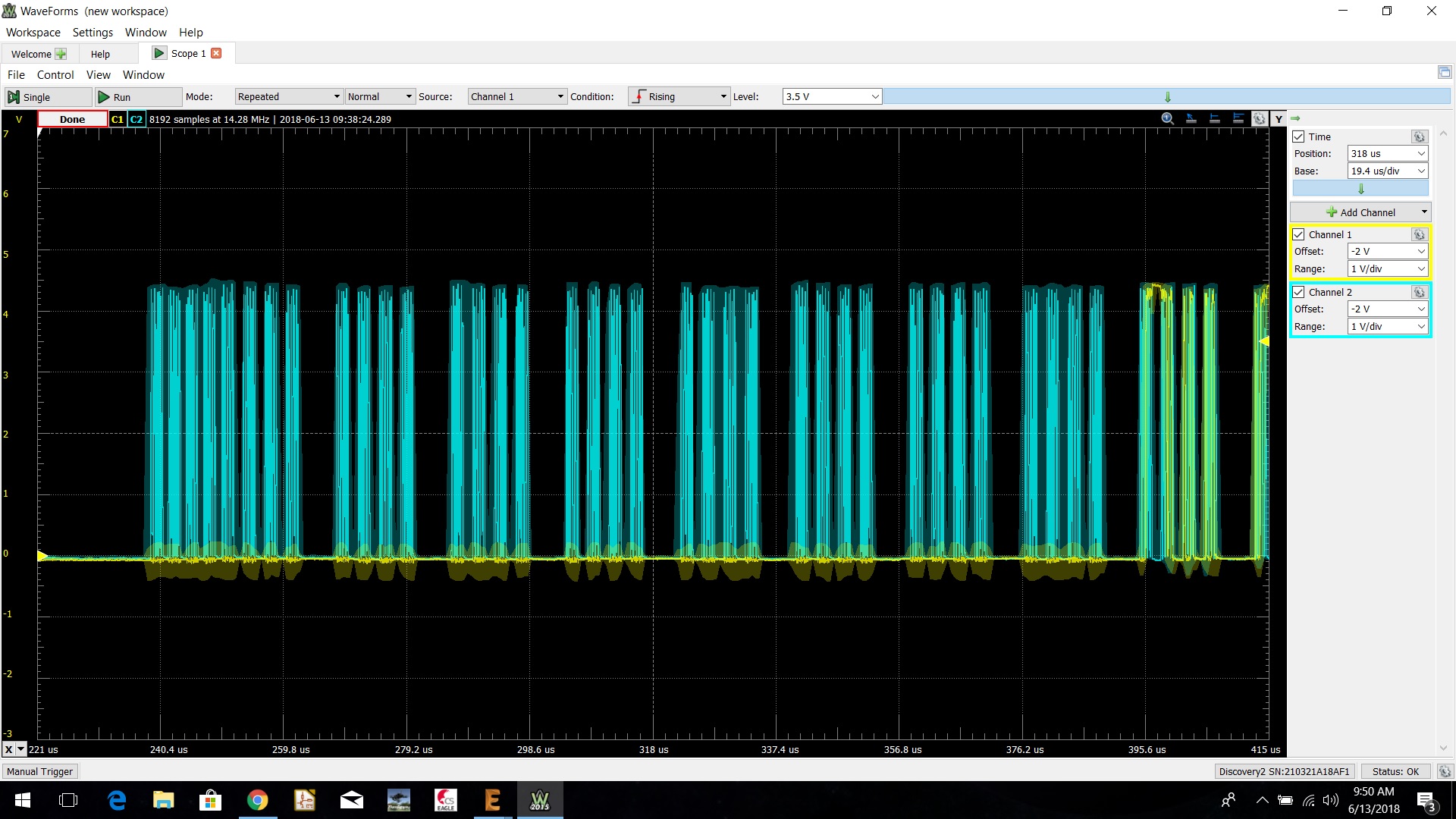
10k view of the start of the data transmission
The first read of the scope is what you're seeing above. The blue trace is clock, the yellow is data, the vertical scale is 1V/div and there is no load. What we're looking at is the start of the data transmission from my ProMini. Each of those blue chunks (that are about 3uS) is 8 bits, so from the left you see the 4 start bytes, followed by 4 bytes for each LED on the 8-Stick that's going to be feeding the other boards. After those first 8 LEDs get their respective marching orders, the data line goes active with the clock. Both signals are going 0-4.5V-ish. FWIW, my code is sending data for a long string of LEDs because I had them all attached in series originally, so it should easily be sending enough data to light up all of the parallel boards.
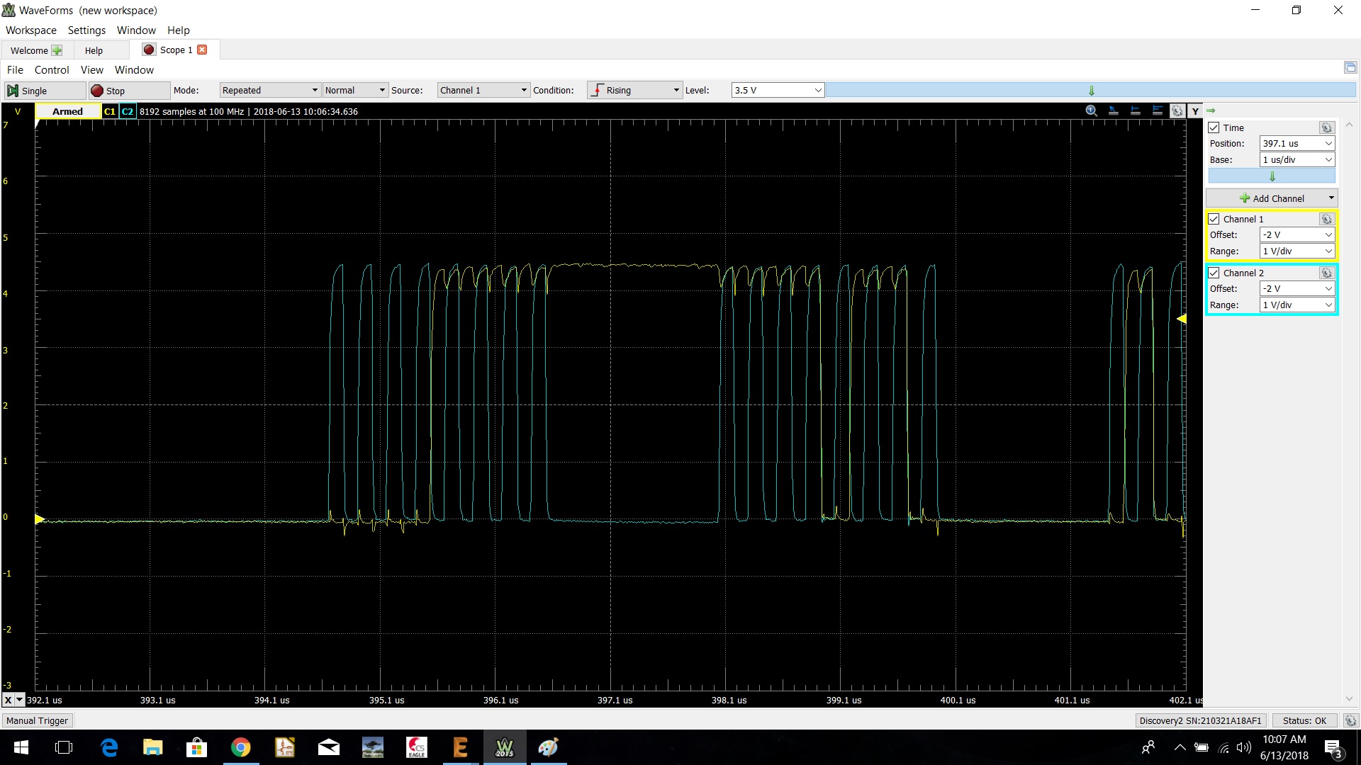
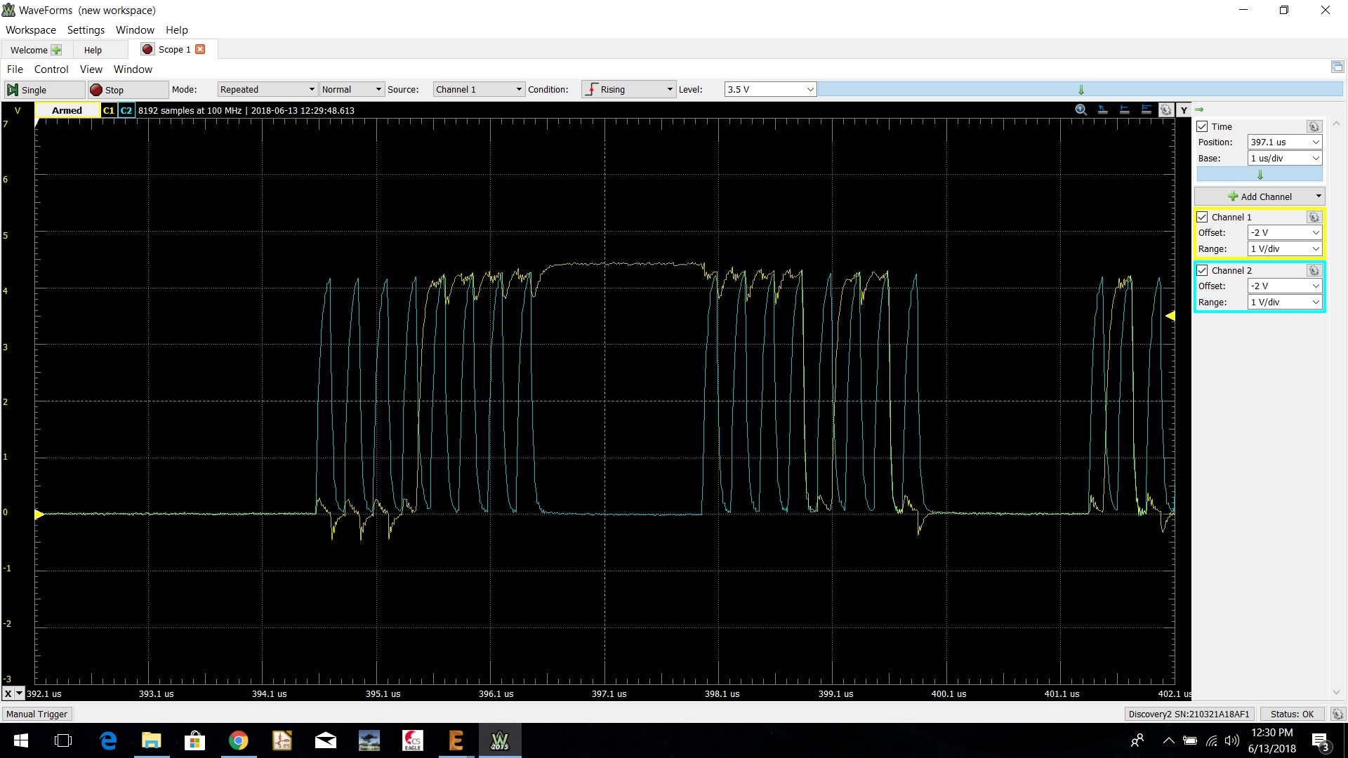
Close-up of the data
Getting a little closer in, we see a couple of arbitrarily chosen bytes about 397uS from the trigger point. We learn a couple of things from this capture. First, those leading edges are not sharp, most likely from my jumper-wire probing that's adding capacitance to the circuit. It also looks like there may be some interaction between the clock and data drivers, given the peaky-ness of the data line during clocks... or that might also be an artifact of my janky probe. Last, the data line stays high between those 2 bytes. That's my sloppy code at work. Bad dog.
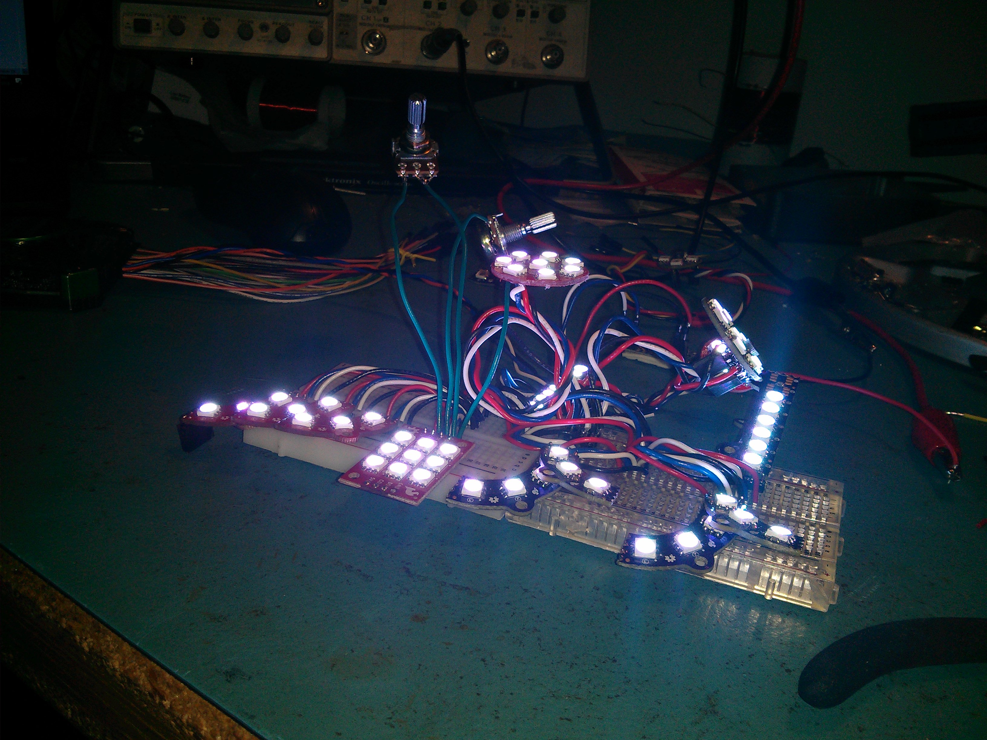
In the heat of the test. It's much worse to look at than this lets on.
I'll spare you some of the more boring details of this test. Suffice it to say that I added progressively more boards (14 of them) and the signals got worse, but it never quit. Check out the scope below.
14 boards attached and all's mostly well
From the above capture, it looks like some more capacitance has been added to the line (which we expect) and the signals are achieving a lower top value (around 4.2V). Again, that charge time is certainly augmented by my jumper-wire probes and the breadboard, but it looks to be increasing. Still, this functions with 14 boards in parallel. But where does it fail?
I don't have any more boards I can attach, and clearly it's going to take a bunch more. So... we cheat. I put a 100k pot on the data line and dialed down the value until the parallel board section started reading weird values (as indicated by colors other than white, or LEDs being entirely off).

Failure achieved
The condition that produced the above plot is an additional 180 ohm load on the data line. The data line rises to about 2.3V, making the current sourcing capacity of the output driver about 12.8mA. But check out the clock line when the data line goes high. We're clearly loading the driver supply, as well as the driver itself, in the APA102C as indicated by the reduced peak voltage of the clock line when both lines are high. Further testing (a second pot on the clock line) showed that the combined output currents of the clock and data lines is limited to that 12.8mA, they can't both drive that much independently. So each line can't be loaded with more than about 360 ohms, assuming the loads will be equal from x-number of boards attached to the output, making its max drive current 6.4mA.
OK, so... how many boards can we feed from a single APA102C output? Can I measure the input current on either the data or clock line and divide that into 6.4mA? Turns out... nope. Those inputs are definitely CMOS, which means no DC current path. Oh sure, there's got to be some leakage current there, but not enough to keep those inputs from floating around 4.5V when not attached to an output that's actively driving it to some value. I even read the floating value with all 14 boards in parallel, thinking at least one of the inputs would have to be out of spec and pull it down, but no dice.
That makes our answer ALL THE BOARDS! No, not really. But lots, certainly. If you can keep the lengths between boards sufficiently short to reduce capacitance, reflections and such, I'm sure the number is quite high. At some point you would need to start thinking of this spaghetti monster as a really bad transmission line, but small-scale operation looks promising. Admittedly, I didn't have to run all of the boards off of a single APA102C output. I could have used the ProMini directly, or an op amp as a buffer/driver. But part of my interest is in radiating and repeating light installations using Lumenati boards, so this was the data I needed to verify that operation.
As I mentioned at some point, the desk-lighting setup I had these previously involved with was a series string like you would normally expect. But adding lights in this setup becomes a pain because you have to change the code to accommodate more LEDs. After a year or two, I may not be able to find the code that runs my workbench light. When I put them back together this time, they'll be in parallel.
Interested in learning more about LEDs?
See our LED page for everything you need to know to start using these components in your project.


A few more comments (after thinking a bit in the shower)... I'd say that there's a very high probability that the chip in these parts is made entirely (or nearly so) of "standard cells". That almost certainly includes the I/O cells. Given the cost of doing a "characterization" of the I/O capabilities, I'm not really surprised that we don't see anything in the manufacturer's spec, especially as in what they've probably envisioned as the only "use case" of having the parts daisy-chained, it's a moot point. (Amazing how narrow minded the marketing types can be sometimes!). Given that we don't know which standard cell library the manufacturer (more likely, the foundry) is using, and it may even be a proprietary one, I'd guess that we'd be safe by taking just about any CMOS "fan-out" spec we can find (sorry, I don't have time at the moment to go dig out my 4000 series data book ;-) and running with that. Also, having worked in the semiconductor industry for 20+ years, I'm well aware that such things are typically set way on the conservative side, so that in reality a "typical" device might be able to drive several times more other devices than the spec sheet says, but only a very tiny fraction of actual production parts won't "cut the mustard".
On a somewhat related tangent, CMOS I/O cells (almost) always include "protection diodes" (typically a zener diode in parallel) for ESD protection (or at least an attempt at it). About once or twice a decade, I run into some bizzare problem where one (or more) of these diodes is having a problem -- I recall once in the 70s a friend was building a Heath Kit, and asked for my help in debugging it. There was a "5V" circuit regulated by a zener and a couple of resistors to power this part of the circuit -- the circuit was "functional", but the LEDs it powered were very dim -- I tracked it down to a bad protection diode in a 4000 series IC drawing way too much current for the simplistic "regulator". I happened to have that IC back at my apartment, so ran home and got it. (Being a Heath Kit, the part was socketed, so it was simple to change out.) I've run into others, but only one or two a decade.
Hi Pete!
I toyed with the idea for a project that would use just one programmable LED - it was the easiest solution to get a program-controlled color and brightness LED, with using only two pins, and thanks to the library from our friends over at Adafruit, doesn't require a bunch of programming or need to mess directly with things like PWMs that using an "ordinary" tri-color LED would demand. One of the possible variants I had in mind was that rather than just having one LED, have 4 or 5 LEDs in parallel. (The project might have gone forward had the LEDs been available in a 10mm package. I wasn't going to mess with the RGB ones just to get the 10mm package.)
So, I think that the parallel question is legit.
BTW, the project I had in mind was a wireless "whose turn is it" indicator for card/board games. With friends gabbing around the table, we sometimes lose track of whose turn it is... and sometimes someone gets up from the table to "refill" (or "defill") and a flashing "your turn" light at their position might remind them to "hurry up"...
One other comment: as for finding the code later, isn't that what GitHub is for? ;-)
Hey '773!
For the "who's turn" indicator, I think the problem you'd run into is that people will forget to hit the button (or whatever) to advance the indicator. So that would really benefit from some kind of automation, and I'm not sue what form that would take. Maybe some voice recognition of the words "aw, you suck!" or some variation on that theme... just thinking outside the box, here. Maybe an accelerometer under everybody's chair to sense their cycles of agitation, like the person that just relaxed just finished their turn. Or some kind of IR or thermopile to register the heat coming off the players' heads? But alcohol will probably mess that up (sugar makes my head sweat - truly weird).
As far as the github jab... yeah, you're right. But that's the sort of project that I'm likely to put the barest amount of effort into. I need a light, how quickly can I pull this off and then forget about it? I'm definitely not trying to justify, but I am admitting to a shortcoming with regard to personal work. And I know I'm not alone...;)
I'd thought, at first, about something like a "big button" or an "arcade button" (actually Adafruit has ones that are clear or translucent white so are more amenable to programmable LEDs), but these all have the down-side of needing a lot of clearance behind the panel that they're mounted on, so what I was leaning towards was using an LED in the middle surrounded by copper tape and using that as a "touch sensor".
As for the forgetting to hit it at the end of their turn, I was considering doing something with average turn time, and the light getting more demanding (and maybe even some sort of sound effect [the "Jeopardy tune", maybe?]). That, combined with the glares of other players, and loudly cleared throats, can often be effective. Fortunately, the folks I get together with to play games don't indulge in alcohol (or other intoxicants), at least not while playing games. (There are a couple of us that are pretty competitive when it comes to card/board games.). And we know when to switch from sugared sodas to just water. Problem is that even just drinking water I have to get up when "my cup runneth under" (remember the "math underrun errors" on mainframes?).
As for finding code later, giving projects meaningful names (not the easiest thing to do with the Arduino IDE) can help a lot, provided you don't get bit with being "sloppy on backups" -- guess how I know that!