The Great Ceramic 3D Printer Experiment, Part III
Follow along as Feldi attempts to build a ceramic 3D printer using OS plans she found online.

Hello, friends. It has been a while since my last progress report on The Great Ceramic 3D Printer Experiment (catch up on parts I & II). Fear not, for this project is still very much alive.
As a quick reminder, I am following OS designs for a Delta 3D Printer by Jonathan Keep. He has generously posted everything one needs to build this project...except a step-by-step tutorial. This is a daunting project and is definitely beyond the limits of my comfort zone. Thus far the process can be described as "two steps forward, one step back," but I am learning a ton along the way and that's really what it's all about.
Last time we left off, I had finished building the basic structure of my printer...
for the second time.
My next step was to make the pulley system, for which I needed to build some parts and then put a few together, none of which made sense to me. Luckily I work with some very talented mechanical engineers, so I have all the help I need in figuring this out.
First, I set out to make the parts circled in the image below.
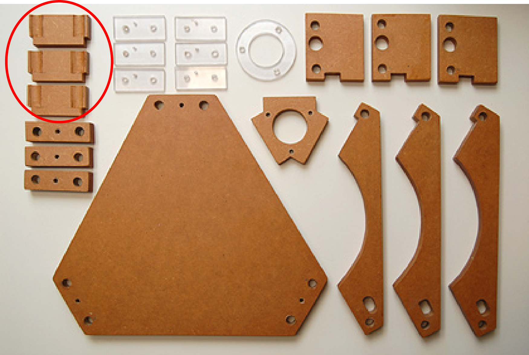
I was deeply perplexed about how to make this part. Yes, the measurements are provided, but that shape is complex. I decided to enlist (Pearce) to help me figure it out. Pearce modeled the part and sent me a printable file, which took him maybe five minutes. I am not a modeling pro - heck I am not even a modeling novice - so I have no idea how it was modeled, but [I can share the file with you!](link text Let us all collectively thanks Pearce for his great contribution in this project. Thanks, Pearce!
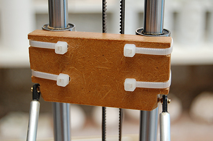
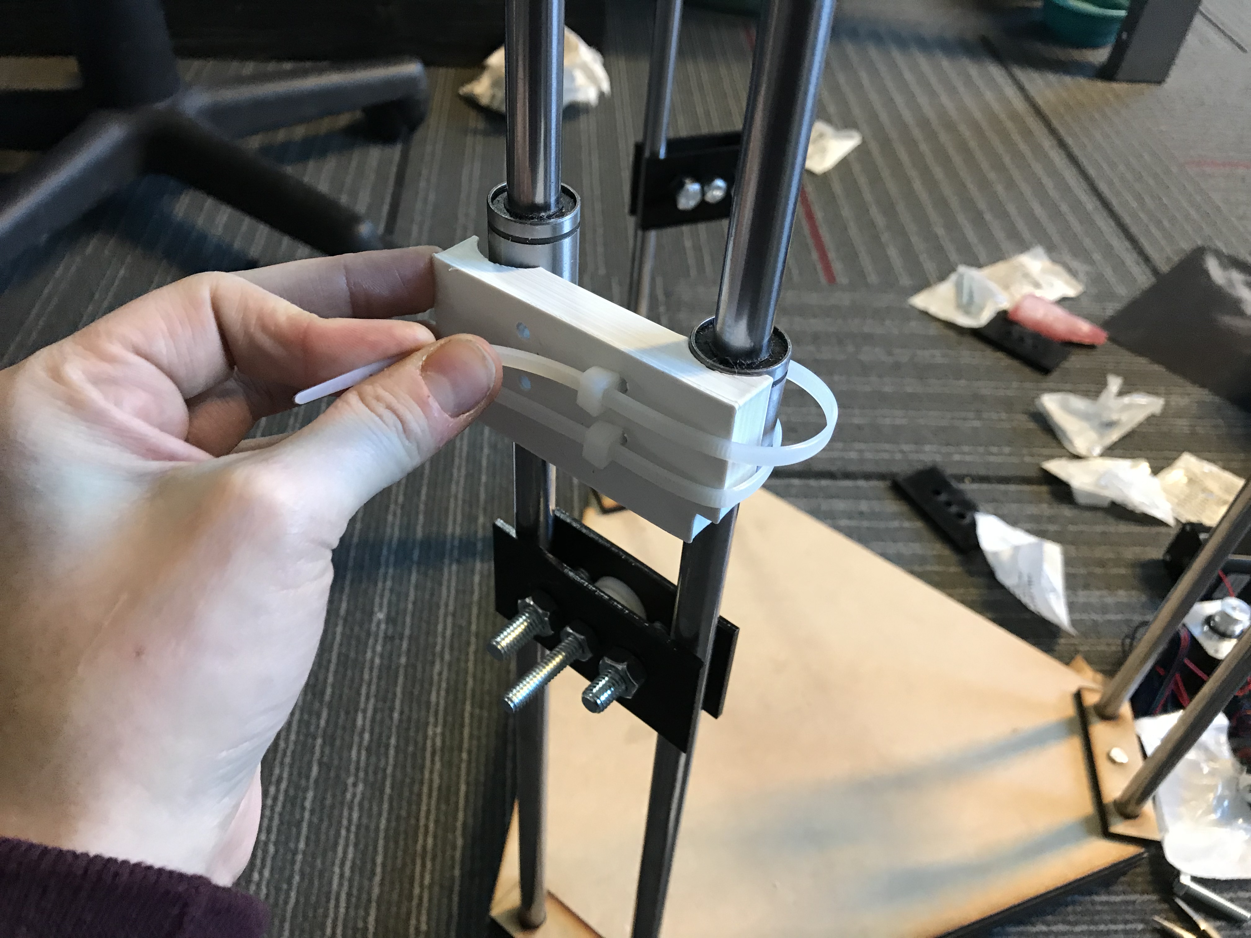
As soon as I finished printing these I realized that they attach to the linear bearings via zip-ties as you can see in this image from Keep's website:
At this point, I had two options:
1. Edit the model to accommodate the zip-ties and reprint.
2. Drill holes in the printed parts like a heathen.
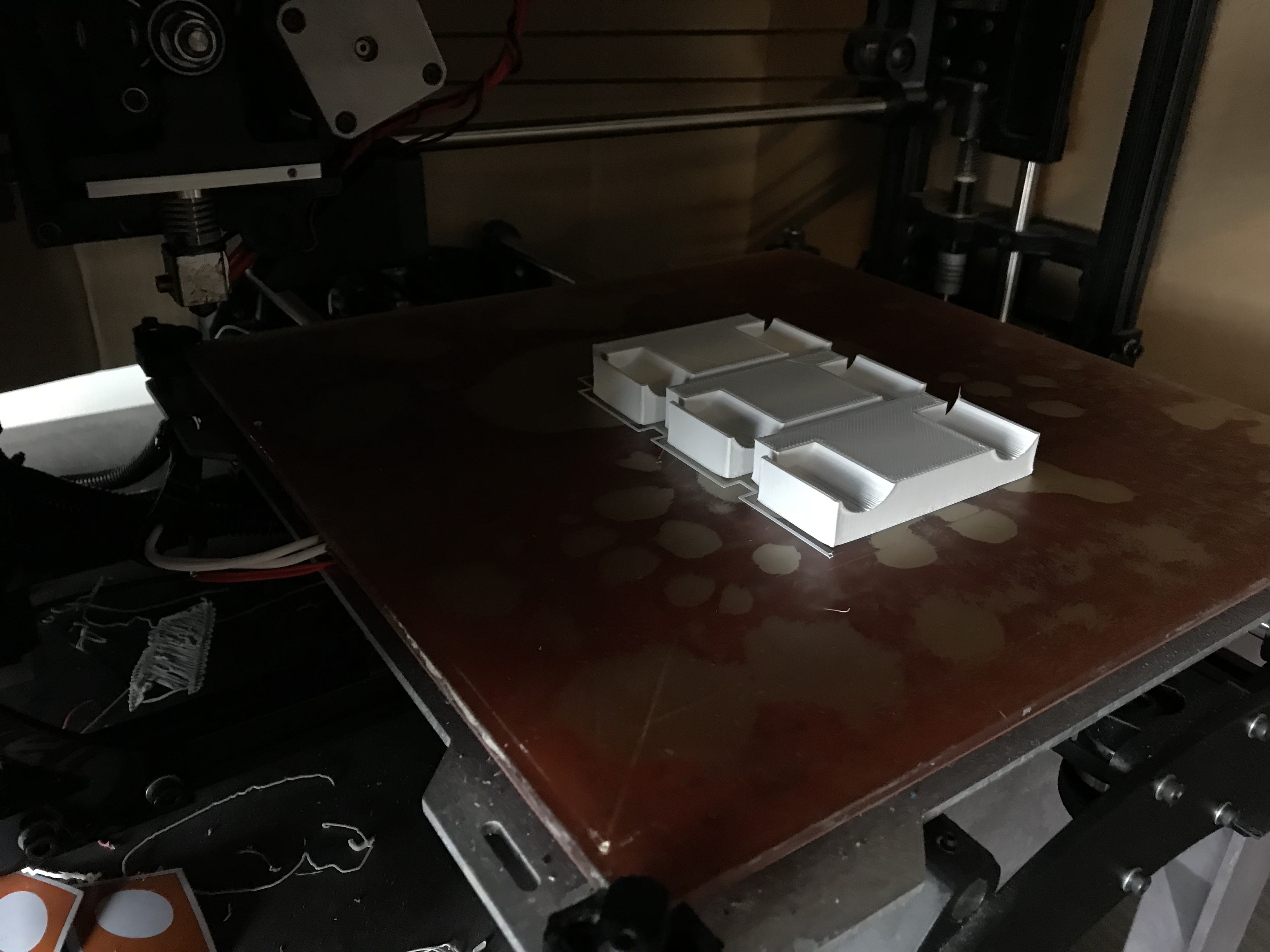
As you can see in the image below, I went with option two.
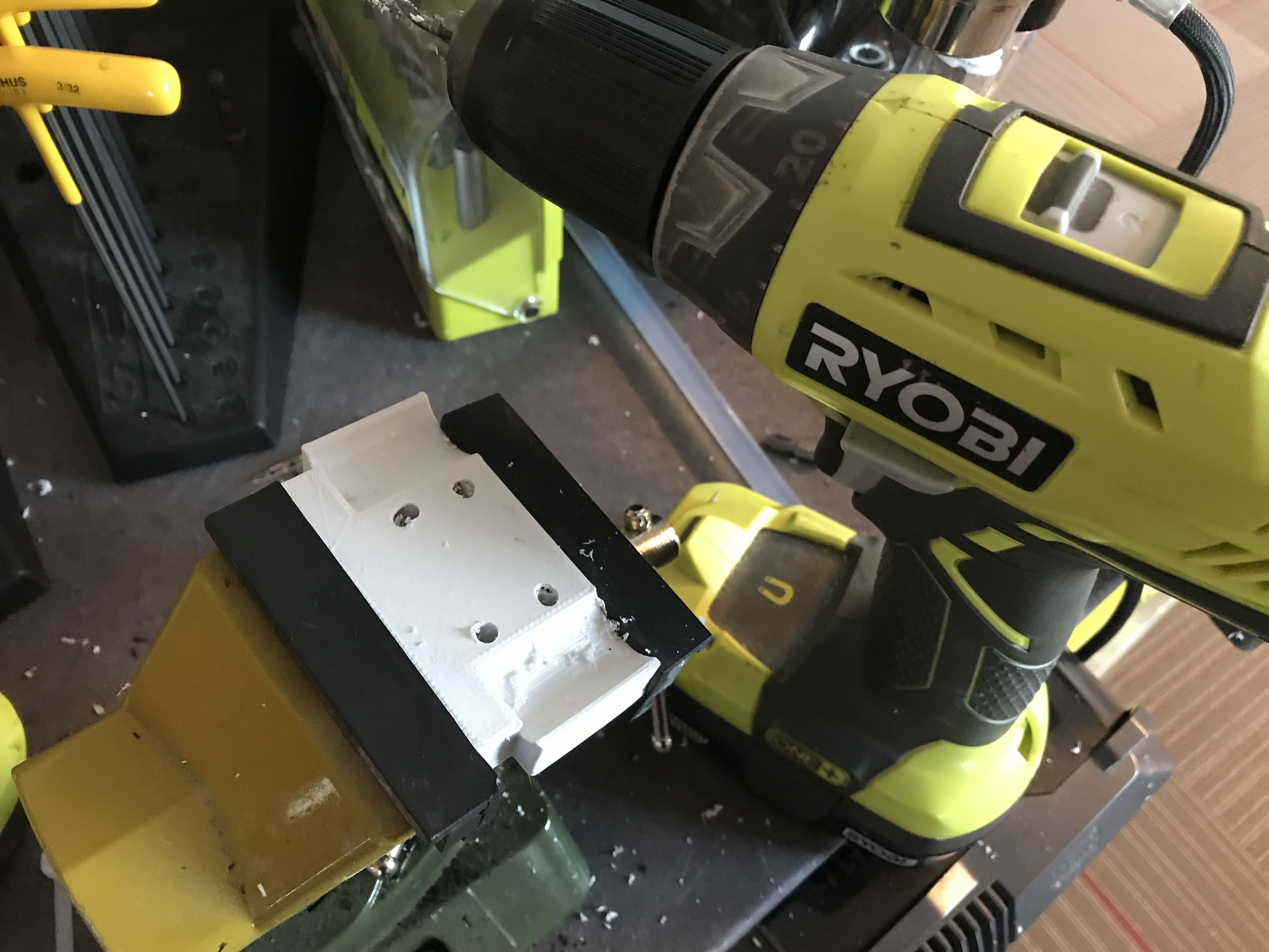
It was actually a perfectly fine solution, and I saved myself a few hours of extra printing.
Next up was building the tension. Here is an image of what we are looking at from Keep's site.
He also provides some files that can be used to machine this part on the laser cutter, but I ended up designing my own based on the hardware we had lying around.
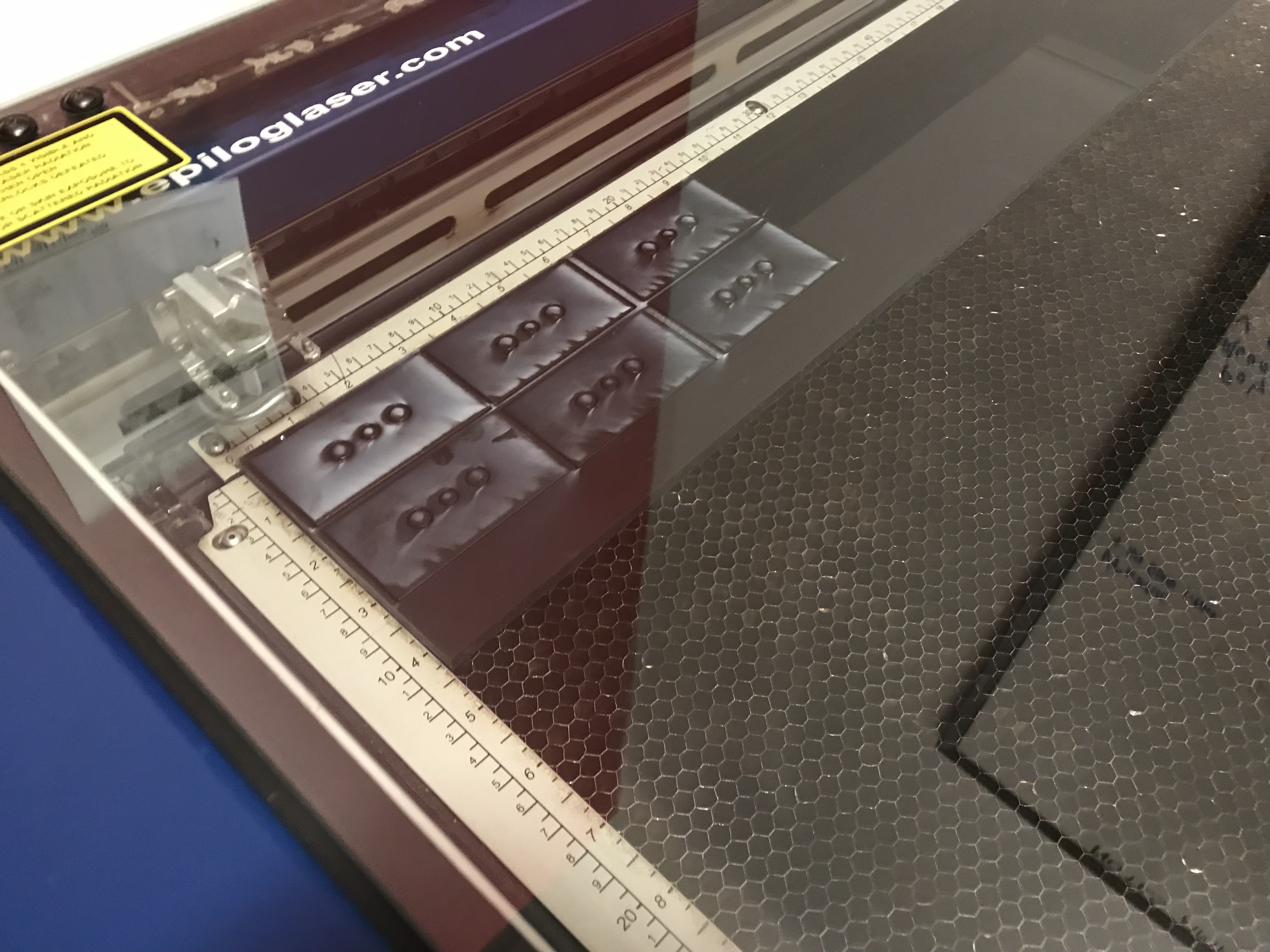
I started by cutting this part out of Delrin for strength. I assumed this part would eventually be moving, and thought Delrin would be stronger than acrylic. Cutting the Delrin took forever, and in this design I did not account for the bulky nuts on the hardware I was using as you can see below.
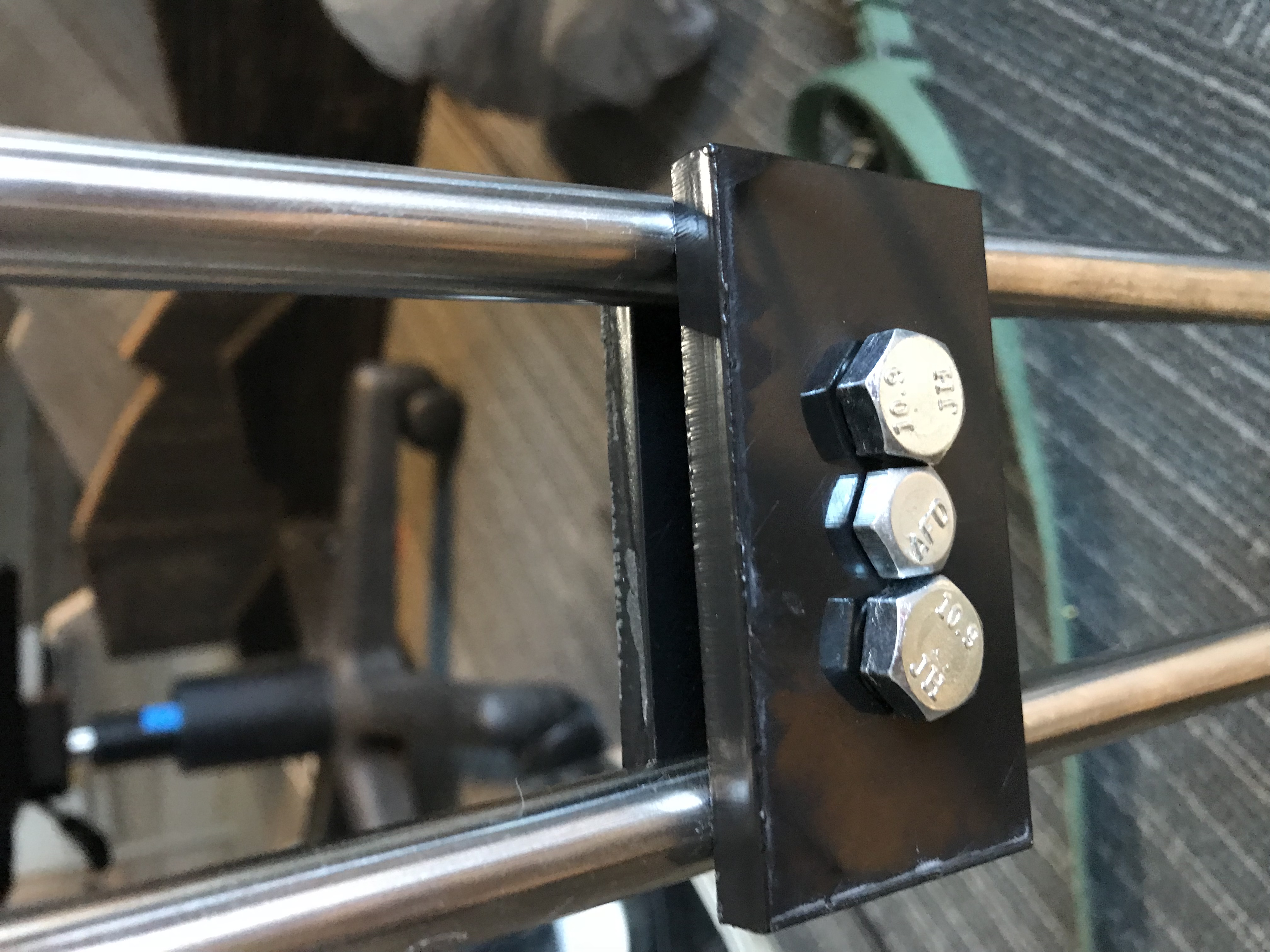
Unfortunately we only had (relatively) bulky hardware lying around so my part does not look quiet as elegant as Keep's, but elegance was never the goal here so I'm OK with it (Edit: no I am not. My deep-seated need to make things look pretty is overwhelming and I will probably re-do this later to make it look better because I am who I am).
Elegant or not, the hardware was too close together and needed to be spread out.
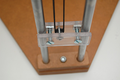
Since I learned this part does not move, I decided to cut the second iteration out of acrylic because it's cheaper and much easier to cut.
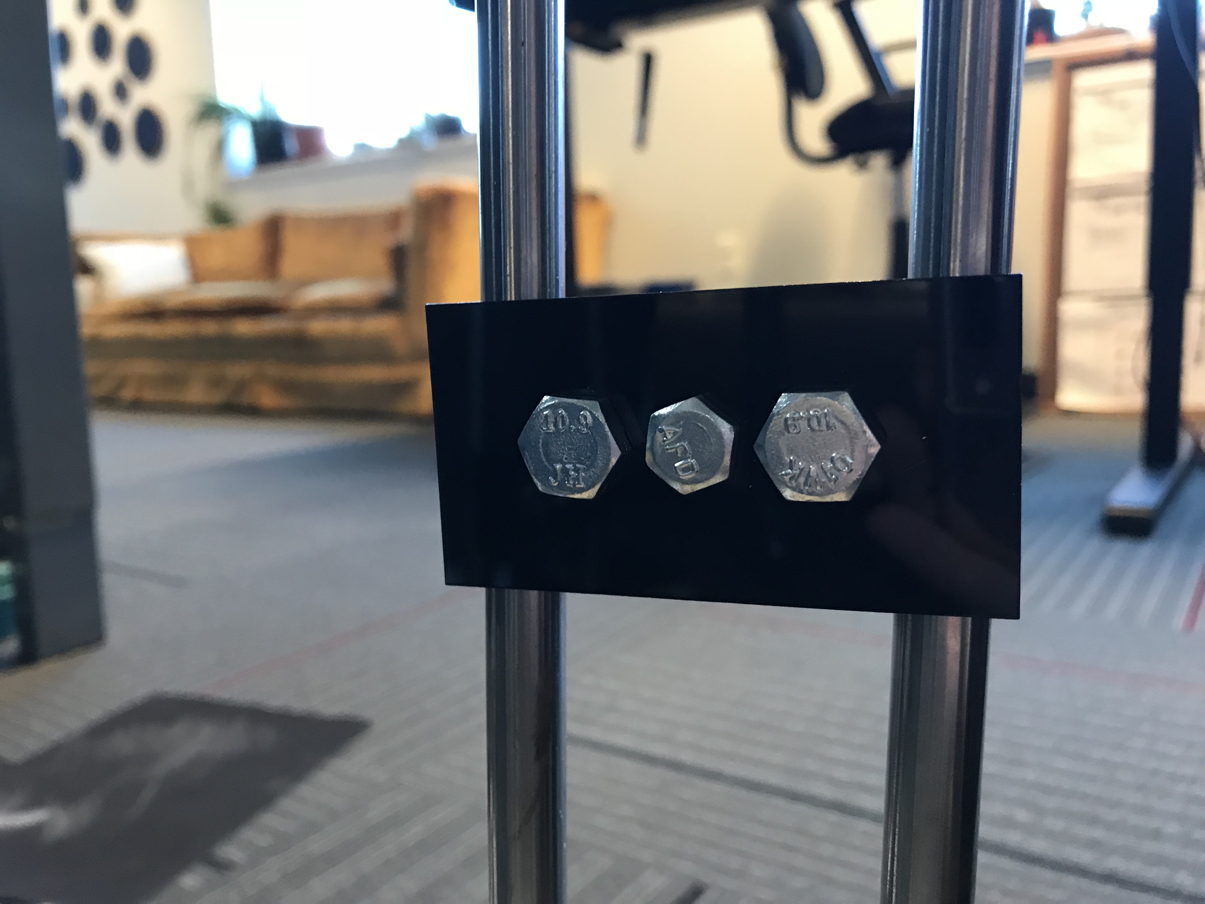
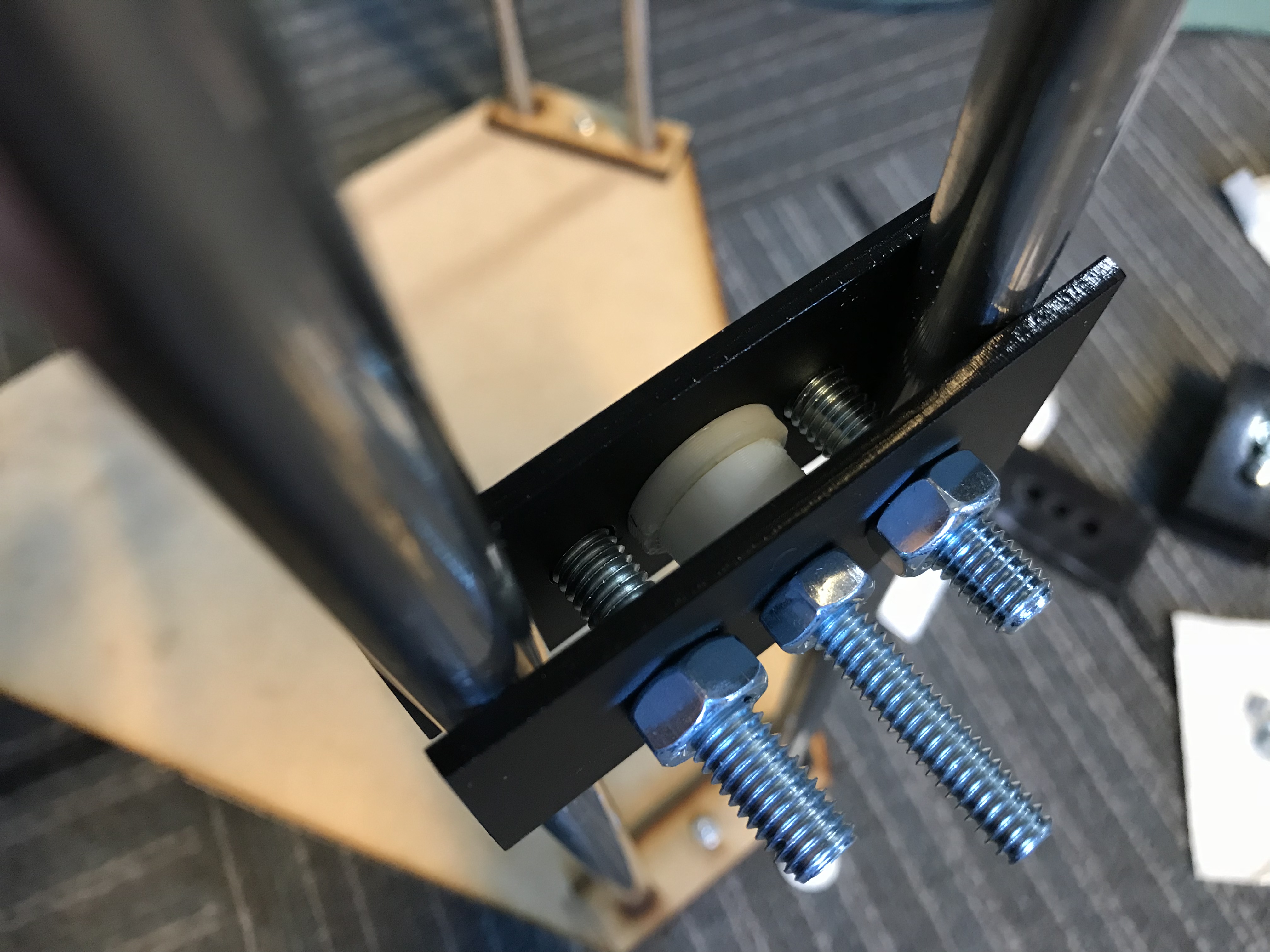
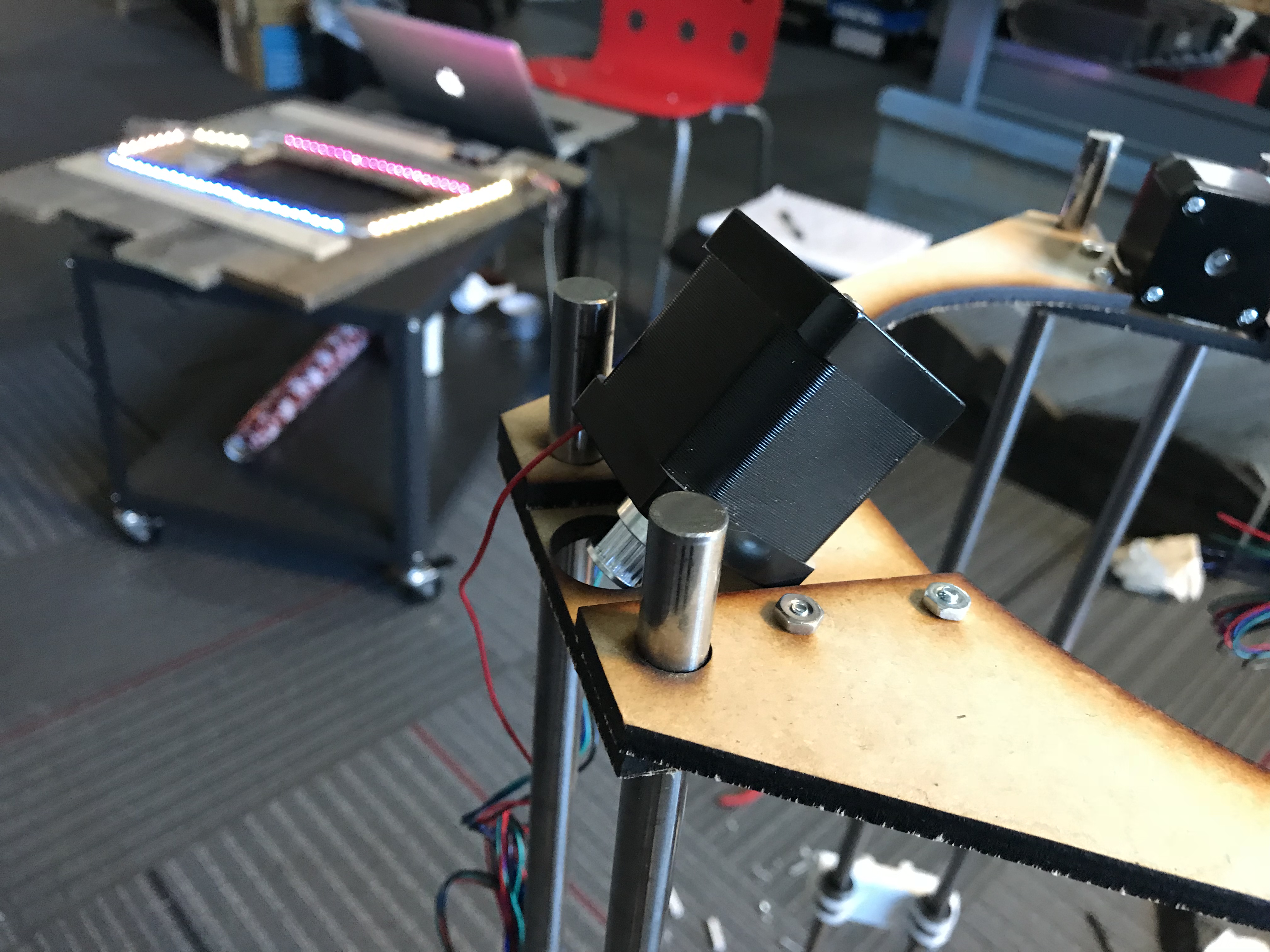
You can see here that there are three screws. The two on either side hold this part in place against the rods. The center screw acts as the tension for the pulley. In order to (hopefully) make this work smoothly, I added a 3D-printed part around the middle screw to keep the belt from moving around too much. Our very own Evan helped me make this part.
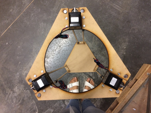
There is one more piece of hardware involved with the pulley system – the motor. The three motors sit snugly at the top of the printer structure.
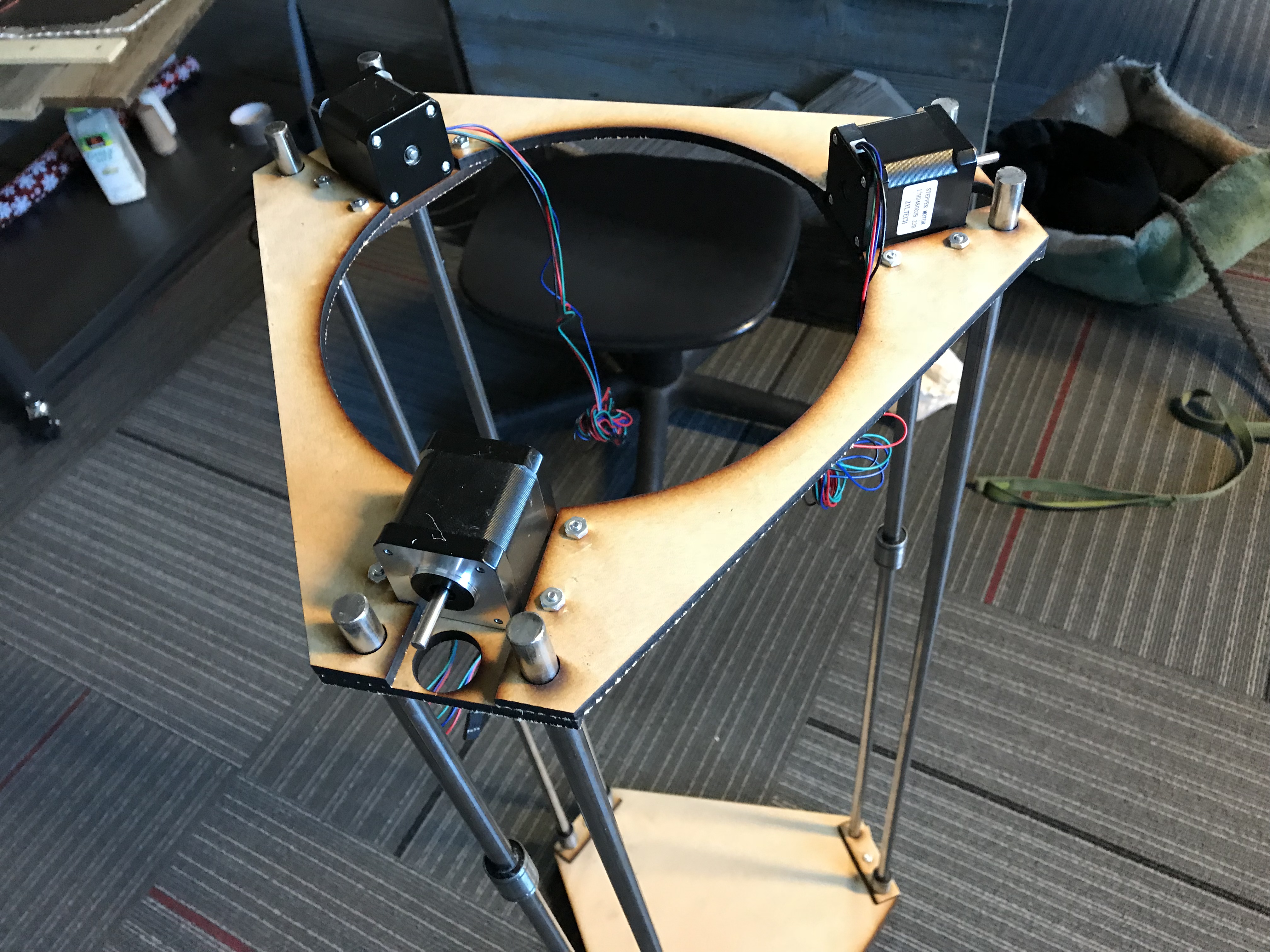
I added a pulley to each motor so they can effectively control the belt.


The last step was adding the belt. There were two parts to this: First, the belt needed to be cut to size and clamped together into a loop. Second, I needed to somehow attach that point of connection to the moving linear bearings.
In order to make the belt a loop, I used 3D-printed clamps modeled by Evan.

It was tough to get the belt in there. I ended up having to use tweezers to make enough space. I think that may have compromised the structural integrity of the part by stretching it out.
I also needed to attach this to the moving linear bearings. It was pretty awkward and I'm still not entirely sure what to do.
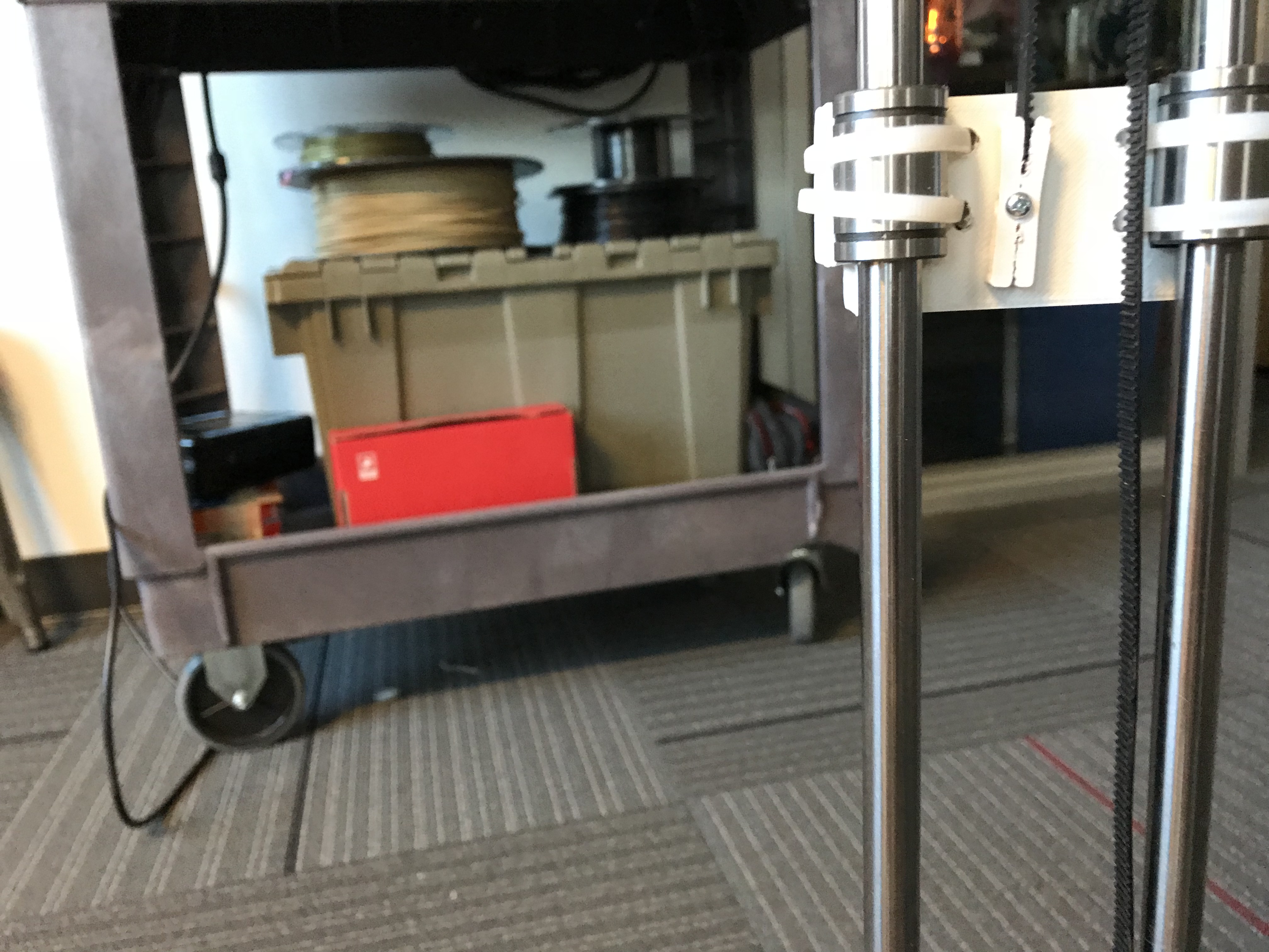
I attached the 3D-printed clamp object (the one that holds the belt) to the 3D-printed object attached to the linear bearing with a screw. Then, I started to move the linear bearings up and down. The first issue I found was that the motor moves with the pulley and ends up looking like this:
No bueno. I added a zip-tie to hold the motor and that worked really well. (This would be a good time to note that Keep explicitly calls for zip-ties on the motors on his site. I just breezed right past that part and discovered it was necessary through testing. Paying attention to the documentation would obviously make this a much easier process, but again, I am who I am.)
Here is a video of my second test, this time with the zip-tie around the motor:
There was a little slack but I was confident I could make some adjustments and get everything nice and taut. That was until this happened:
If you look closely, you can see that one end of my belt is NOT in the clamp as it should be. What did I learn? My 3D-printed clamp is not strong enough to hold the belt as it pulls the linear bearings up and down. I'm going to need to figure out a new clamping system, as well as a way to attach that to the linear bearings. I'm going to talk to a few folks who are more adept at mechanical engineering than myself to help come up with solutions, and that will be where we start the next installation of The Great Ceramic 3D Printer Experiment.
I sincerely thank all of you who are following along as I fumble around on this project. Please join the conversation in the comments below. I would love to hear everyone's ideas, suggestions, and thoughts!


See https://www.youtube.com/watch?v=ZzO9skEYqwY the first few minutes he talks about securing the belt level to the rails. Might work for you as well..
Thanks! Will check this out! :)
I am really liking this series. All of us make mistakes, and it's all too common to edit them out, which can be discouraging. I like all the help you're getting making models for things, and the different tools and techniques you're using to make a different sort of 3D printer. I also like the pictures and descriptions of where things went off the rails: if I can learn from someone else's mistakes, I'm that much ahead (granted, being I am who I am, I too will skip over something important, make the same mistake, then realize I could have saved that time had I paid more attention).
I'm really happy to hear that you like the series! I always think it's best to be honest about the messiness of the engineering process. Glad you think so too!
I have a delta platform that I built when I first started with delta printers and I dont need it anymore. I can send it to you. It should help with some of your mounting issues.
How is this project coming along? Is it dead? The first 3 articles were very interesting!
I have some time reserved in April/May to work on it some more! Stay tuned :)
Underneath the bed in this photo https://cdn-images-1.medium.com/max/1400/1*VT8zmx72LXqSe37mgRbtCA.jpeg you'll see the piece that holds the belt which works well for me. you can pull it tight through and then loop it back around and it holds well. I've also added a binder clip across it to press onto the belt and it seems to help. But I still have to re-tighten the belt a few times a year.
You only have zip ties holding the stepper motors in place?? Those screw holes on the face of the stepper motor are there for a reason—to keep the motor body from moving instead of the shaft. There should be plates screwed to the motor and slotted into the support to take the reaction torque.
Thanks for the tip! The zip tie is actually working really well so I'm going to leave them as is, but maybe for V2 I will use the screw holes on the face.
I just love that serie. I have been waiting for an update since august!
Really hope you find a way to secure that belt.
I'll try to post about it more frequently! Glad you like it :)