Enginursday: Multiple I2C Ports on ESP32
I'm using six of the same sensor in my fiber optic suit, with only four hardware configurable addresses. I need to take advantage of my ESP32 to create multiple I2C buses.

For as long as I've been at SparkFun (longer actually, this project started back at school), I've been working on a fiber optic light suit. The idea originally came about because I was frustrated with the lack of controllability of EL wire. It's only monochrome and, as far as I can tell, most inverters don't have the required duty cycle for PWM. I wanted to have glowing wires all over me but didn't know where to look.
A friend who was also interested in the idea bought me a roll of some thin fiber optic from a supplier in Texas, and I was off to the races, hot gluing bundles of fiber optic and simple 5mm LEDs into Starbucks straws (my part-time college job) and putting them all over my arms.

Version two of the Light Suit at a Pretty Lights show in 2017
I've come a very long way since then. Four versions later, I've moved from "dumb" LEDs in straws and bulky PWM controllers running on a relatively slow Arduino Pro Mega that I had left over from a digital electronics class, to shiny, custom PCBs with SMD APA102s, 3D-printed mounts, an ESP32 Thing Plus and even I2C based finger-bend sensors that eventually became a SparkFun product. In versions three and four, I made the move to add legs and a torso to this glowing suit, adding a whole host of new problems. After version three had issues staying plugged in, I took a step back and collected my thoughts before starting again.
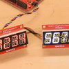
I finally gathered the motivation and time to pick this project back up and figured I'd tackle my problems getting my six I2C gesture sensors to pull some readings, four of which are the ADS1015, ADC-to-I2C-based Qwiic Flex Glove Controller, and read how bent all of my fingers (excluding my thumbs) are. The other two sensors in the feet are also ADS1015-based boards that attach to force sensors; this enables me to see how my weight is balanced.
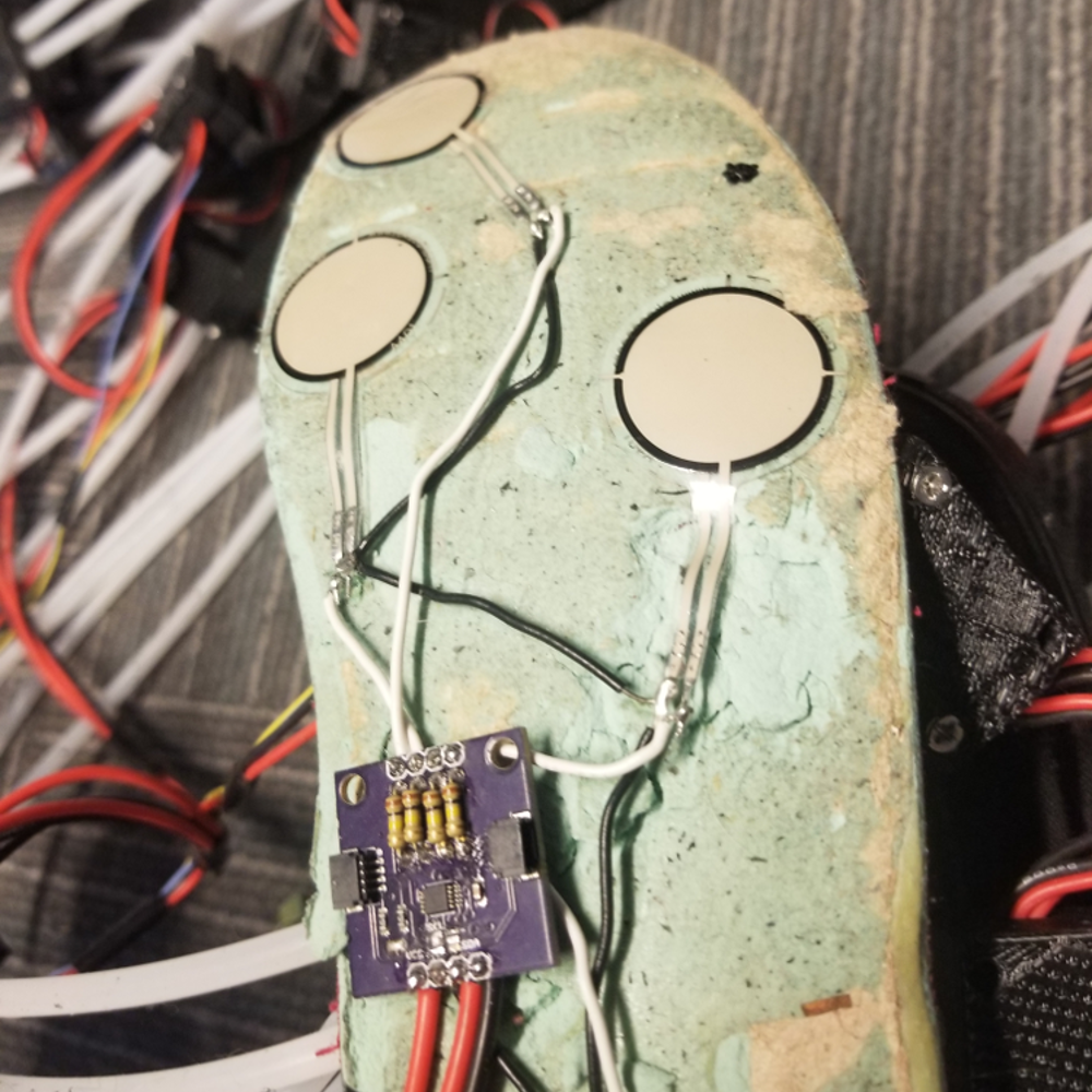
Weight-sensing insole
The ADS1015 has a hardware configurable address; tie the ADR pin to GND, 3V3, SDA, or SCL to select one of four available addresses. If you're a math genius you'll realize we have more sensors than addresses. That's a problem our trusty ESP32 can solve. We'll simply need to create an I2C bus for each side - this way we can have each side be a mirror image of the other in code. To do this, we first need to include a few libraries and create our I2C buses.
#include <SparkFun_ADS1015_Arduino_Library.h>
#include <Wire.h>

TwoWire leftBus = TwoWire(0);
TwoWire rightBus = TwoWire(1);
We'll then say which addresses we want our sensors to be on as well as create the objects for our sensors themselves, since we have two buses, we'll only need to use 3 addresses.
/***Addresses for Different Parts of Limb***/
#define PINKY 0x48
#define INDEX 0x4A
#define FOOT 0x4B

/***ADS1015 Objects***/
ADS1015 leftPinky;
ADS1015 leftIndex;
ADS1015 leftFoot;
ADS1015 rightPinky;
ADS1015 rightIndex;
ADS1015 rightFoot;
In our setup loop, we initialize some Serial output to see what's going on, we then initialize our left and right buses on two different sets of pins. I also use 100 kHz as I've got some pretty long wires, which hinders I2C communication. We then add our gesture sensors to their respective buses using their respective addresses. No need for an I2C Mux today! Note that I also change the gain of my sensors; this is specific to my project and sensors, so you won't need to do this for your accelerometer or other I2C device.
void setup() {
  /***Debug Output***/
  Serial.begin(115200);
  Serial.println("Startup");

  /***Initialize I2C Devices***/
  leftBus.begin(23, 22, 100000);
  rightBus.begin(16, 17, 100000);
  leftPinky.begin(PINKY, leftBus);
  leftIndex.begin(INDEX, leftBus);
  leftFoot.begin(FOOT, leftBus);
  rightPinky.begin(PINKY, rightBus);
  rightIndex.begin(INDEX, rightBus);
  rightFoot.begin(FOOT, rightBus);

  /***Change Gain***/
  leftPinky.setGain(ADS1015_CONFIG_PGA_1);
  leftIndex.setGain(ADS1015_CONFIG_PGA_1);
  leftFoot.setGain(ADS1015_CONFIG_PGA_1);
  rightPinky.setGain(ADS1015_CONFIG_PGA_1);
  rightIndex.setGain(ADS1015_CONFIG_PGA_1);
  rightFoot.setGain(ADS1015_CONFIG_PGA_1);
}
My main loop() is as simple as printing the values out over Serial!
void loop() {
    for (int channel = 0; channel < 2; channel++)
    {
        Serial.print("LP");
        Serial.print(channel);
        Serial.print(": ");
        Serial.println(leftPinky.getSingleEnded(channel));
        Serial.print("LI");
        Serial.print(channel);
        Serial.print(": ");
        Serial.println(leftIndex.getSingleEnded(channel));
        Serial.print("RI");
        Serial.print(channel);
        Serial.print(": ");
        Serial.println(rightPinky.getSingleEnded(channel));
        Serial.print("RP");
        Serial.print(channel);
        Serial.print(": ");
        Serial.println(rightIndex.getSingleEnded(channel));
    }
    for (int channel = 0; channel < 4; channel ++)
    {
        Serial.print("LF");
        Serial.print(channel);
        Serial.print(": ");
        Serial.println(leftFoot.getSingleEnded(channel));
        Serial.print("RF");
        Serial.print(channel);
        Serial.print(": ");
        Serial.println(rightFoot.getSingleEnded(channel));
    }
    delay(50);
}
And here's the output below, notice how all of the feet values are resting close to 0, as the circuit the board they are on doesn't include the op-amp circuit.
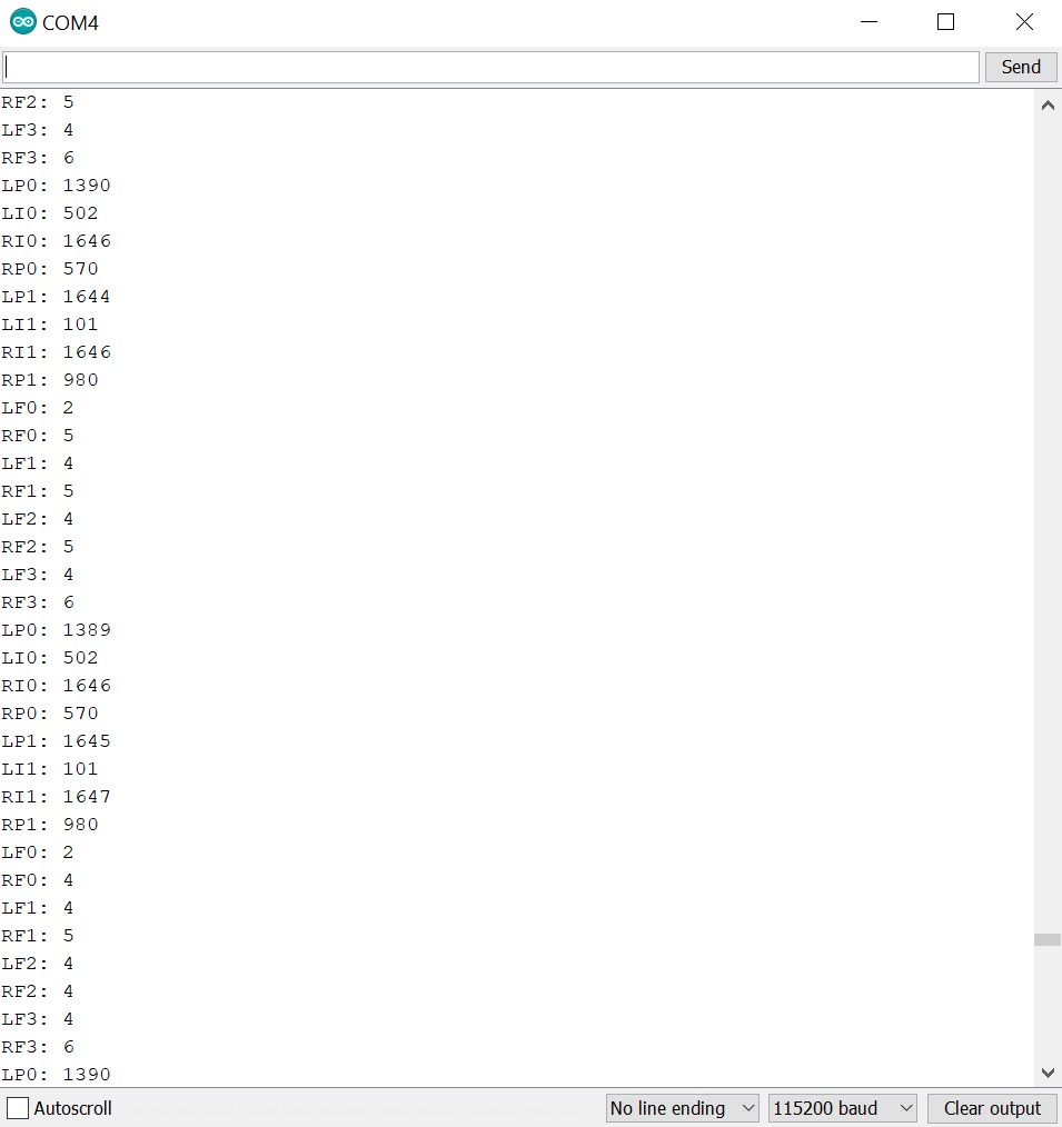
Serial output from all four limbs


If you can tolerate running an extra wire to each ADC, you can run as many of those ADS1015s as you like on one bus. That part watches its ADDR line continuously, so you can use it like a chip select -- drive one low and talk to 0x48, while all the others have their ADDR lines high and are listening for 0x49.
Woah, that's a clever solution!! I thought it simply sampled the line at startup. If I had known that I probably would've made sure the ADR pin was broken out on all of my ADS1015 based boards!
I'm a bit worried about the insole sensors shown in the photograph: back in the 70s, we used to joke about "waffle testing" circuit boards when we couldn't figure out what was wrong with them. What's a "waffle test"? Glad you asked! Place circuit board on floor and apply "waffle stomper" (Vibram lug soled boot) firmly. Always solved the problem!
Alternatively, the circuit board could become more painful than a rock in your shoe...
I was also super worried but I can't feel the board at all through the insole which I was fairly shocked by. Hopefully the Qwiic connectors on the board will prevent inadvertent waffle testing out in the field (I think the added spacing should prevent the ADS1015 from getting too squished