Enginursday: Light Suit Update
I have finally gotten the hardware in (mostly) working order for my wacky fiber optic light suit. Let's check out what I've done!

The Wonderful Mistakes I've Made to Get to this Point
Pretty much as long as I've been playing with electronics I've been working on this wacky Light Suit project to wear out to festivals to light up the night. I've learned so much along the journey. I've made so many Enginursday posts about it that at this point you may be getting sick of the project, but I feel an obligation to keep folks updated all the way through the end.
When I arrived at SparkFun, I was in the second iteration of the project and I needed to fix a few 3D parts. I wore this updated version to a few shows and quickly broke the gesture sensing that I had soldered into my hands. I came back into the office on Monday and bang! The SparkFun Qwiic Flex Glove Controller was born in order to isolate the exceedingly fragile solder points on the Flex Sensor. From here, I decided to scrap the second version as the 1-mm thick fibers I was using were brittle and hard to work with.
The Current Light Suit
In the third version I got a lot closer to the vision in my head. I designed some custom PCBs to mount addressable LEDs to instead of individually PWM-ing each Common-Cathode LED (I still have unplaced anger at whoever let me live so long without knowing about the WS2812). I was also able to use the SparkFun Qwiic Flex Glove Controller that I had designed after the failure of the second iteration. I sourced new fiber to test some neat audio-reactive and gesture-reactive code.
However, I had one major flaw: the LED modules I had were connected via Qwiic cables as I had this strange obsession with making the system solderless for easy repair out in the wild. This worked for a little bit, but some of the cables had a little bit less friction with their receptacles, so exuberant movements would promptly unplug things. Also, the cables would occasionally break from the connector after a lot of movement.
The moral of the story here is that you'll need some pretty sturdy plugs if you want to use them with any sort of wearable. Qwiic cables, while useful and readily available, were not necessarily the right choice for this application. I was also having problems figuring out how to create multiple I2C ports to listen to all of my gesture sensing equipment. However, I solved most of these issues in the fourth iteration of the suit.
The Brain
To control the whole operation I made a custom board with an ESP32-WROOM. I started my design from SparkFun's ESP32 Thing Plus design. From here it was a matter of changing a few things to suit the board to my purposes. I substituted the CP2102 Serial Converter for a CH340G, as it's easier to hand place/rework. I also added breakouts for I2C and LED data lines in each corner of the board to control each limb of the suit. I tossed on a MEMS microphone for audio reaction. I also gave it two 18650 batteries in series and a 5V 3A LDO to give me voltage for my LEDs. I admit that this could've been done far better (at full charge, the LDO has to drop 3.4 volts, gross) but give me a break, I've got a strip of these LDOs and they're not gonna place themselves in designs.
In the future, my plan is to put the batteries in parallel with some sort of charger IC that I haven't had the time to source, as well as the beefiest Boost regulator I can find. Anyway, there's always room for improvement, but check out the board below.
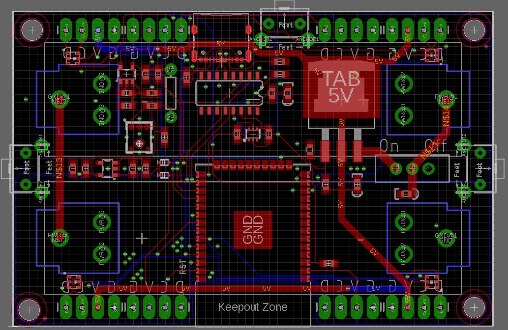
The Brain for the Light Suit
This guy then sits in a small 3D-printed box that sits right where a belt buckle would go, I send my belt through part of the box to anchor it to my body.

3D Printed Brain Box
LEDs and Fiber Optic
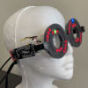
Now that we have control figured out, we'll have to get some LEDs mated up to fiber optic. For this, we'll use an itty bitty custom PCB with two APA102 LEDs on each side.
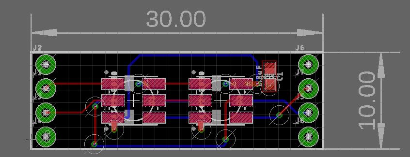
LED Board
This fits in between two identical 3D-printed parts, which align the PCB and LEDs with four strands of 5mm diameter fiber optic. Screwing these together clamps down on PCB, fiber and control/power lines all at once for a secure fit.

Fiber-LED Grip
This 3D part is then sewn onto some custom adjustable armbands (shout out to Mom for letting me use her sewing machine). We cut up a ton of fiber optic to the proper lengths and connected it all up.
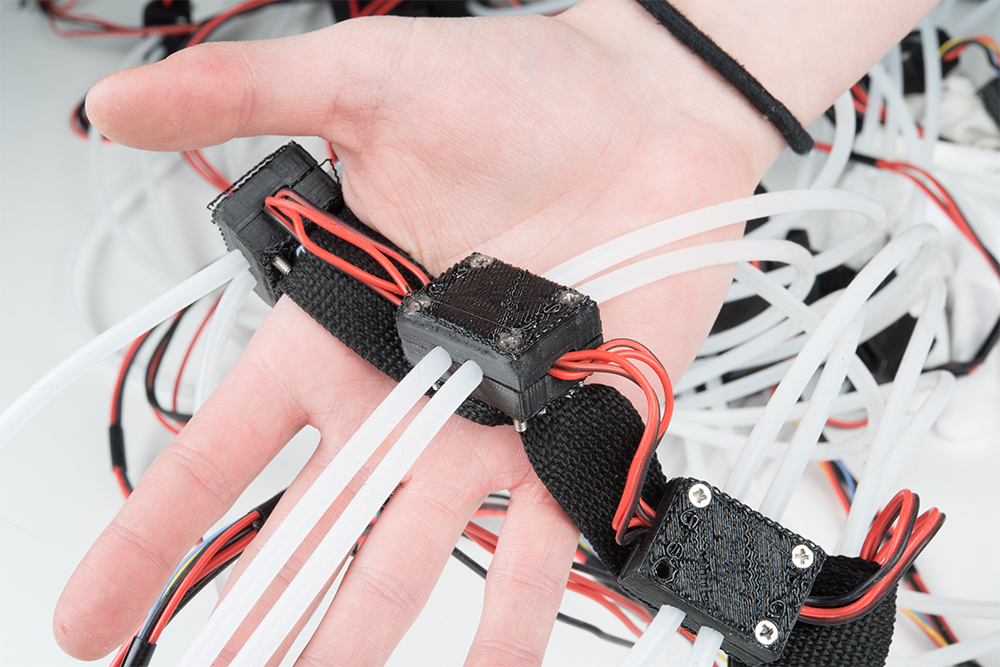
Single Fiber Grip Module
Controls
I go through a detailed analysis of my gesture controls in this blog post about using multiple I2C ports on ESP32. However, I basically have two of the SparkFun Qwiic Flex Glove Controller sewn onto each hand. In each foot I have a custom board, based on the same ADS1015 Analog->I2C conversion chip as the gloves, that senses how my weight is balanced on each foot. I have two I2C buses broken out from my ESP32, one for the hand controls and another for the legs. As I was monkeying around last night, I realized that I'd bent a few of the sensors in travel (the demo always works, right?) and they don't really sense so well anymore. Due to this, all I really got to look good for video was the audio buffer portion. Check it out below and stay tuned for a final code update.
Interested in learning more about LEDs?
See our LED page for everything you need to know to start using these components in your project.


I have a Bike Lights project that is quite similar using side glow and APA102 led strings. One thing you may find useful is to mask off the first couple of inches of fiber with black shrink wrap. That part of the fiber is usually much brighter than the rest. The contrast makes remaining fiber seem pretty dark. Also try lighting up the fiber from both ends. It makes a beautiful analog color gradient and you have only used 2 LEDs to get the effect. For audio effects check out this graphical equalizer chip https://www.sparkfun.com/products/10468. Run the outputs into some A/Ds and save a lot of processing power while still getting lights cued to the music. Cheers!
This is a really cool project. At first, I wanted to see more of the fiber optic "lines", but the way you have it now looks great, as the lines appear to "flow" and travel up and down the suit! Great job getting the pulses synced to the music!
Well done!
Thanks so much! One of my goals was to try and make it look a little more organic this go around. I'm very excited to tailor it and pull some of the lines in to give it a more fitted look.
To get the pulses I store audio data in a buffer and then the further you get down the arm the further you are down in the buffer. Now the idea is to get gesture induced pulses going the other way and find some nice way to mix the two together. Anyways the code is below
Great suit! Nice writeup, too.
My one comment is that I wish you'd turned around in the video so we could also see what it looks like from the back. (Just out of curiousity, did you consider being able to sit down while wearing it?)
Thanks! I believe I turn around about 10 seconds in but without much sound you can't really see the structure of the suit. I also had a loose clock wire on the left arm that would cause everything to freeze on that limb occasionally, this prevented me from moving around too much.
I did consider sitting down in it as it's meant to be worn for hours on end, as well as be compatible with riding a bike, it's actually pretty comfy as some of the fibers just sort of move out of the way so you end up not having to sit on any of the LED modules
I still have to adjust a few fibers in the legs to prevent that "bowed out look" as well as prevent them from getting caught on any parts of my bike.
This is sweeeeeet.
Thanks! I thought you'd appreciate, fellow connoisseur of glowing dance suits.