Enginursday: On the 555 Timer
For decades, the 555 timer has been a mainstay of hobbyist electronics. Is it time to retire this venerable little workhorse?

I recently had a brief Twitter dot com exchange wherein a less-experienced but still very capable "pro-am" electronics hobbyist was asking whether FETs could be driven directly by analog voltages. It turns out, she was hoping to control a motor's speed using a pot, without an Arduino in the mix, to create a high-power, variable-value resistor out of the FET.
Naturally, the first suggestion that popped up was "throw a 555 timer at the problem! Done!" I took issue with that, and I'm going to explain why here.
What is the 555 timer?
If you are relatively new to electronics, having come to it through Arduino, Raspberry Pi, or robotics, you can easily be forgiven for not knowing exactly what a 555 timer is.
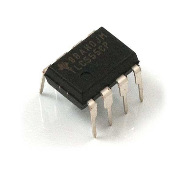
The 555 (or "triple nickel" as it's sometimes called) is one of the oldest integrated circuits around. It was introduced in 1971; commercial integrated circuits had only been on the market for about 10 years at that time. Unlike most early ICs, which typically had several copies of a single gate, it combines several different logical blocks into one package: two comparators, an S-R flip-flop, a buffer and an open-collector output.
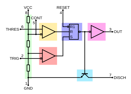
Diagram in public domain, courtesy Wikipedia user BlanchardJ
The basic concept is fairly simple: by looking at one or more analog voltages (with the comparators on pins THRES and TRIG), generate a digital signal on a buffered output pin, and the inverse of that signal on the open collector output pin. Typically, the voltage(s) used for comparison come from one or more resistor/capacitor circuits; the time required to charge (or discharge) the capacitor(s) determines how long the outputs remain high (or low).
Applications
We typically divide 555 applications into two groups: astable and monostable (bistable is also possible, but as that's just basically ignoring a lot of the circuitry to use only the flip-flop, it's uninteresting and I won't discuss it any more).
Monostable configuration
In a monostable application, an input signal is monitored for transitions. When a transition occurs on that input signal, the 555 circuit outputs a pulse of fixed length, regardless of the time between the triggering transition and the signal returning to its prior state.

Image derived from public domain images (waveform and circuit) by Wikipedia users InductiveLoad, JacksonMiss, and BlanchardJ).
Comparing the circuit diagram with the block diagram above, it's fairly easy to see what's happening. The DIS and THRES nodes are at VCC when the trigger occurs, as is the non-inverting input of the the lower comparator. That causes the output of the lower comparator to go high, triggering the SET input on the RS flip-flop. The BJT connected to the DISCH pin turns off, the output buffer turns on, and the capacitor C starts to charge through resistor R. When the voltage on the THRES pin exceeds 2/3 VCC (a fixed level, set by the three resistors in the block diagram above), the reset input on the SR flip-flop triggers, activating the BJT, draining the capacitor rapidly, disabling the output buffer, and setting up the circuit for the next triggering input.
I'm not going to get into the math of why, but the output pulse will be approximately 1.1RC, where R and C are in ohms and farads. Thus, a 10k resistor and a 10uF capacitor will yield about an 110ms pulse.
Where is this used? Anywhere we need to create a fixed-length pulse from an unknown input. Maybe you want a light to come on for five seconds whenever a button is pressed, or a horn to sound for five minutes if a door is opened. It's also used if we want to ignore rapid transitions on the input: any triggers received while the output pulse is active are simply lost. This makes it a good circuit for removing switch bounce from inputs to digital circuits.
Astable configuration
In the astable configuration, the circuit oscillates of its own accord, producing a square wave output of a frequency and duty cycle, determined by the selection of capacitive and resistive elements in the circuit below.
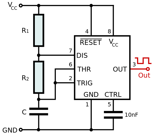
Image in public domain via Wikipedia; for revision history and credits, visit the Wikipedia source page.
The cycle here is somewhat more complicated, but similar to, the monostable case, with the exception being that the TRIG and THR inputs are tied together to create a situation where one is true and the other false during some period of the oscillation.
Again, leaving out the deriving math, the frequency of the circuit is 1 / (0.693 * C ( R1 + R2 ) ) Hz, with C in farads and R1 and R2 in ohms. The high time is 0.693 * C * (R1 + R2) and the low time is 0.693 * C * R2.
We can immediately see that the high time is always going to be larger than the low time; thus, the duty cycle will always be greater than 50 percent. That can be mitigated by putting a diode in parallel with R2; this changes the equation for the high time to R1 * C * ln((2Vcc - 3Vd)/(Vcc-3Vd)) where Vd is the forward voltage of the diode you used. Of course, now your duty cycle is tied to Vcc and will vary if that's not stable...say, if it's derived directly from a battery.
Finally, if you want to adjust the duty cycle on the fly, you'll need to replace one of the resistors with a potentiometer. But, tweaking just one of the resistances will change the frequency as well as the duty cycle!
Confused yet?
In defense of the 555
So, in defense of the 555 based solutions above, they're cheap. We sell 555 timers for $0.95US; if you're willing to buy more of them, or dig through datasheets to make sure you're getting the one you want, they can be had for somewhat less from the major online parts distributors. The passives are pennies, although you need to lay out a few bucks to get a good resistor assortment and capacitor assortment to ensure that you'll have the various values you need to cover most situations. Overall, your average 555-based solution is likely to cost near $1US, give or take.
Of course, if you put any kind of value on your time and frustration, this is a pretty expensive solution. You've got to do all the math I spelled out above and try to tweak the resistor and capacitor values that you actually have on hand to produce the results you're looking for; there are a number of different online calculators available, but even with those, you can be off by 10 or 20 percent, or more. Plus, if you discover that you need a different frequency, you've got to recalculate your values! And don't even get me started about temperature coefficients, power supply rejection ratios, and part tolerances!
There's got to be a better way!
And there is! Several, in fact.
- The Arduino Pro Mini - For $10, you can replace the entire circuit with an Arduino Pro Mini. The code to duplicate the function of either of the above circuits is very simple, and can be easily modified to change the duty cycle and frequency of an astable circuit or the pulse length of a monostable circuit. Not only that, but you get a "free" processor to do other stuff with, AND you can emulate several 555 circuits with one processor!
- The Servo Trigger - For servo-based problems, the servo trigger is a good solution. While a 555-based solution gives you the ability to set and hold a position, usually by adjusting a potentiometer, the servo trigger allows you to react to external triggering events, slewing from one position to another and back automatically. It's much more expensive, at $20, but if you want to avoid programming and have a "one-and-done" type of solution, it's hard to beat.
- The ATTiny85 - For size, it's hard to beat the ATTiny85. You'll need a programmer; we sell one designed specifically for this part. It's also (once you have the programmer) the cheapest solution; at $2.84US, it's not much more than the 555 and the passives needed to make the circuit work. It also has the same benefits as the Arduino Pro: you can emulate several 555 circuits with one chip, it's far easier to change the frequency and duty cycle, and you have a processor that can be used to do some other stuff if you need it.
Your mileage may vary, no purchase necessary, void where prohibited by law
Another advantage of the two programmable options here is that learning them adds a huge and extremely versatile tool to your bag of tricks. Getting good at using a 555 timer isn't terribly portable; to go beyond simply plug-and-chug calculating values requires a pretty solid electronics background. If you already know how to program, extending it to implementing a 555 timer's functionality is fairly easy; if you don't know how to program, you're better off spending the time you'd be sweating over capacitor and resistor values learning to program.
Old habits die hard, and using the 555 timer in electronics is one of the oldest habits there is. There are no doubt niche applications where the 555 is the only way to go, but 99 percent (or more!) of the time I see them recommended to a hobbyist, that hobbyist would be way better off using some kind of programmable solution.


.png)
I too must disagree. You make the point that learning to program a microcontroller has benefits elsewhere. This is true, but learning how passive analog components actually work and how the math behaves also has benefits elsewhere. The fact that the 555 can run on a wide voltage range, run on dirty power, and source or sink a whopping 200mA also makes it a low parts count solution for many problems. The original (bipolar) version is also very robust, and will operate reliably in an environment full of interference and voltage spikes. While I agree that microcontrollers have encroached on much of the territory the 555 originally held, there are still plenty of niches where it's still arguably the reasonable choice. Hans Camenzind (the designer of the 555, alas no longer with us), wrote an excellent book on IC design. At the end, he revisited his own 555 design, explaining how he'd do it differently with decades more advancement and experience. But the original design persists.
Remember Occam! Sometimes there really are applications where a simple non-programmable fixed-frequency oscillator is all you need. 555s don't get out of tune too easily ;) and overkill necessarily implies wasted capacity of some sort, often significant. Using an Arduino Pro Mini in place of a 555 seems to me the equivalent of using a tactical nuke to take out a mouse nest -- and it goes up to two or three nukes, in the case of the pot-and-transistor approach.
On top of the overkill issue -- the idea of just throwing an Arduino at any given electronics problem is a massive trope that's speeding its way towards cliche. There's ample criticism of that approach to begin with (I remember it from when I was still browsing Hackaday, and that ended a year or so ago!) and we don't need to add to it.
I'd be extremely interested to hear, in the scenario put forth at the start of the article (and then never touched again) why the pot-and-FET approach would not work or would be insufficient -- or would even be proposed as bad design or engineering practice. Aside from the fact that IRF510s (the easily available FET that first comes to my mind) start getting out of bed at about ten volts, necessitating a 12v supply all 'round, I don't see a big problem there. (That may be me, though... I don't work with motors often enough.)
Take your IRF510. It's good for up to 5.5A or so. Taking one of the precision gear motors that Sparkfun sells, we find that its stall current at 12V is 1A. So, no immediate problem there. The rDS(ON) is 0.54 ohms. Call it 0.5 ohms for easy math. Fully on, the IRF510 will dissipate about 1/2W at full motor current. By the time the FETs resistance equals that of the motor (12 ohms), the FET will be dissipating 3W due to the voltage drop. Well within it's capability, but pretty wasteful. This, by the way, is why motor control is PWM, whether with FETs or BJTs. Handling large currents through any sort of variable resistance results in a lot of heat.
Now, for the professional reason its a bad idea. Assuming you burn one staff day using a 555 for your design and one hour for a microprocessor solution. Totally unrealistic, but it will help prove the point. Using Jameco, because that's where i was looking at the IRF510 datasheet, the cheapest micro with ADC capability (gotta read that potentiometer) is $0.89 qty 100. The cheapest standard 555 is $0.17 qty100. Let's assume the quantity discount stops there. Lets assume your engineering time costs $120 an hour. It cost you $120 to design in the microcontroller and $900 to design in the 555. Wow, it's a lot cheaper to use the micro right? What happens when you make 100,000 of the widgets you just designed. Each micro controller widget costs $0.72 more to make. All of the sudden you spent $72000 more in parts to save $780 in engineering costs.
The above is a very quick lesson on why something that makes sense in the hobby realm or as a one off solution makes no sense, and may very well doom a product, that will be commercially produced. There is absolutely nothing wrong with using a microcontroller to solve a problem that could be done with a slightly more complex and time consuming, if cheaper job, when you are doing it for yourself. But claiming that the cheaper solution has outlived its usefulness because its old and a bit more complex to understand (depends on your point of view) won't get very far when presented to people who do design work for commercial projects.
You can cut the price differential to $0.12 per part if you can figure out how to read a potentiometer without using an ADC. But that requires the same math that you have to know to use a 555. :)
Using a $2 micro for doing the work of a $0.1 chip (in quantity). Seriously? Maybe hobbyist building a one-off where the labour and price are irrelevant, but for anything else the 555 is still going to win - if for nothing else then because it doesn't need to be programmed. That is an extra operation that costs $$$ unless you are buying a ton of them where you can get them pre-programmed.
I get that Sparkfun is mostly targetting hobbyists and not pros designing for manufacturing, but you should try to educate people about these issues. It would save us from yet another failed Kickstarter where some fools decided to build a smartphone using an Arduino or some similar nonsense.
BTW, if you want to adjust the duty cycle without changing the frequency use a dual 555. First will work as an astable multivibrator and the second will be adjustable monostable flip-flop, "shortening" the pulse length according to the duty cycle required. I have built a fan controller like this, works a treat and costs peanuts.
The $0.1 chip only works until the customer changes requirements or the new rev wants to add features... I don't think I have seen a 555 chip anywhere in the wild outside of a DIY kit or measurement equipment built by 555 fanboys.
One thing your over looking is that a 555 timer is a CMOS component and has a wide input operating range. you can get 555 times that work from 1.5VDC on up. I've use them all the way to 16VDC in applications. You can not do that without lots of extra circuity and a higher cost in all three of your examples above. I agree there are many niche applications for a 555 timer but that aside it is a very powerful chip to know how to use and shouldn't be removed from your bag of tricks if you ever live outside the TTL range. The time taken to do the math calculations to use a 555 timer can be far shorter then the time to code and program an ATtiny as well.
True, most if not all modern variants of the 555 are CMOS, but the original NE555 was a bipolar device and could be had in in a ceramic dip package or a metal can package. Dealing with the BJT bias currents made the math even more FUN.
I have plenty of LM555 bipolars rattling around. I had to actually go out and buy an ICM7555 to get a CMOS 555. That said, the reason why I did that was I wanted a dumb 38kHz oscillator driving a bunch of IR LEDs. The datasheet for the 7555 has a 50% duty cycle circuit that uses feedback from the output. (See figure 2A of the linked datasheet.) There is only one RC component so a simple potentiometer as part of the R of the RC allows a tuneable frequency.
Also, the formula is much easier: f = 1 / (1.4 RC)
I did discover a weakness with that design. I was trying to drive my LEDs using a BJT (2N2222) but wasn't getting the frequency I wanted and was seeing way off of 50%DC. I solved my problem with a small signal MOSFET to buffer the output of the 7555. The base current of the BJT was enough to change the charge/discharge of the timing cap, so the output of the 50%DC circuit needs to be connected to a high-Z input of some sort...
Sparkfun, I can go on ebay right now and find new TI brand NE555P chips, (2$ / 50 chips) + $2 shipping and combined shipping discount for multiple orders, with quantity discounts available, buying direct from China, no middleman. Approaching 4 cents / chip, if you want to argue that you get more value for your money by using a microcontroller instead, the Chinese beg to differ.
If a project legitimately necessitates a microcontroller - fine. If you are suggesting for the sake of simplicity to substitute a microcontroller for a NE555 - no that is a joke, you are just shilling your products on your customers.
Also, when you suggest that a microcontroller should be used instead of NE555 for simplicity: "Of course, if you put any kind of value on your time and frustration, this is a pretty expensive solution. You’ve got to do all the math I spelled out..." This is just insulting to your customer base and betrays everything that "making" and DIY is supposed to be about. Shaking my head Sparkfun....
555 4ever!
I use a lot of 555s professionally, mostly for voltage doublers, triplers and boost converters. In some of these designs it performs equally well compared to much more expensive specialty SMPS ICs. A few months ago I designed a 10W 12V to 80V step up converter using a 7555 for driving LED filaments. I did some measurements on it and at full output power, the efficiency was around 86%, which is quite impressive for a 555 design. On the other hand, when I need for example a more complex sequential timer with multiple outputs or when accuracy and repeatability are important, I would rather choose a small microcontroller.
The 555 Timer is not useless, and can be fun.
It is, however, mostly useless, and is rarely a professional solution to anything... do note, however, that rare things do happen.
555 Timers are rarely the most appropriate IC for timing applications, even when eschewing microcontrollers. Often, Schmitt Triggers are a much more appropriate choice; they’re even much easier to use. By comparison, 555 Timers are needlessly education-y; fine if you want to learn something, but if you just want a good circuit, they’re usually the wrong answer to a problem.
Other specialized timing ICs exist as well that more correctly solve timing problems for a given circuitry problem at a given price-point.
See similar articles here, which appropriately point out those ICs and circuits that, in practice, are simply more appropriate in most circumstances than using 555 Timers:
http://electronicdesign.com/boards/555-best-ic-ever-or-obsolete-anachronism http://www.ecteducation.co.uk/index.php/2010/04/hello-world/
Thanks for writing this article. It’s an interesting (and obviously controversial) topic. Over the years I’ve moved into the ‘microcontroller’ camp.
For learning about analog circuits, using the 555 is a great way to experiment. However, my prototypes always seem to grow in complexity and using a microcontroller keeps the options open. In the example above, you could add motor control features like slow-start, non-linear control and even add feedback sensors to make the system more robust.
Analog circuit design is way more fun and using analog parts can reduce costs. But for getting small projects running, I agree with the author: using a microcontroller is usually best.
I'v had my own experience with the 555's tolerance issues. My first electronic project was making a capacitance meter from scratch based on the 555 timer. It involved logic gates, counters, and some quad IC switches. It basically took the endurance of the on cycle and the known resistor values to find the capacitance of the capacitor. It was a extensive and complex project but it worked exactly as I had planned...except that I hadn't counted on the 555's tolerance range. It made the capacitance readings inconsistent and the project non-practical. However, it was a good experience and it was neat to realize that if the one part had been more precise, the project would have been a success.
As a hobbyist I appreciate the freedom the arduino ide offers me..and specially the attiny85 and 84 which super rock!! also many (or all) of the proyects I get into are either temporary or oneoffs. Having the posibility to program and code my device let me focus on the really important parts of the design..like color and wheather or not my kids will be able to break the 3dprinted enclosure...I believe the original discussion was not weather we should ban the 555.. or forbid its sale.. i believe it was quite the opposite.. it was the allowance that it was an advanced tool for advanced users...
I understand that the beginner is going to have limited knowledge and their tool bag is going to be low. But one of the most important tools to get is knowing how to search for an answer and why forums are so helpful. Just because you can throw a micro at a problem, doesn't mean you should.
For my PWM applications where I need them to be cheap, versatile, and easy to use I recommend the TL494. What makes it so nice is you can use one pot to control the frequency, and another pot to control the duty cycle. They're readily available from digikey for $0.68. I used that IC for my plasma speaker and I was able to get a pretty large frequency range and 0-100% duty cycle, all I had to do was one calculation for my RC value to make sure I was within the frequency ballpark.
I disagree as well. Sure, microcontrollers have their place, but I'm a strong proponent of using the right tool for the job. Sometimes the 555 is the right tool, so use it when it is! This is why so many "Makers" get stuck trying to design a product and ending up with a crappy result. There's really no need to throw a frickin' Arduino at every problem, and the "programmable solution" doesn't teach them a thing about turning their lab bench prototype into a reliable product. And if you're going to promote using a microcontroller, why does it always have to be a stupid ancient AVR? They are what should have been retired a long time ago, IMHO. But then, like you say, old habits die hard.
For simple teaching/art tools like the Drawdio (http://web.media.mit.edu/~silver/drawdio/), the 555 is perfect. Hope I can keep finding it cheap and simple.
The 555 is one of those parts that will probably live forever. I wouldn't use one if I already had designed in a micro, but there are still plenty of strictly analog projects where a micro makes no sense. Other parts that have been around forever, and will continue to be even though there are better versions of them art the 741 opamp, and the 2n3055, mj2955 and 2n2222 transistors. They may even outlive the type 80 vacuum tube! (Introduced in the late 1920's the type 280 full wave rectifier lived on as the type 5Y3G, and 5Y3GT until the late 1980's. Same tube inside, just different bases and shape bulbs)
You list the Arduino Pro Mini for $10, but for $2.95 you can use the Picaxe 08M2, which is easier, cheaper, and has the exact same footprint as the 555.
The Pro Mini is very different than the Picaxe 08M2. The Picaxe is a single chip not a full development board with decoupling caps, crystal, voltage regulator, etc. The ATMega328 (or the ATTiny that was referenced) are closer in functionality and price to the Picaxe.
I agree that they are different, but if you are looking for a 555 substitute for time savings, the Picaxe is cheaper than the Mini, and way WAY easier than an AVR. The Picaxe has a free programmer, and you can build your own programming cable from things you have laying around the house. BASIC is a snap for anybody. It's easier than Python even. Also, I've never used a decoupling cap or crystal with a Picaxe.
But the Pro-Mini comes with the 555 blink by default... change the blink sketch for timing. Minimal brain required. Checkmate.
For that matter, an ATtiny or any of a host of other small micros are in the $1 range in small quantities. You need the programming tool, and some software skills to get at all the peripherals, but they all have internal oscillator options for no-external-component use.
I grew up in the age of building circuits using multiple discrete analog and digital chips until the day I could buy a sleeve of PIC16F688s for about $2.50 each. I can't think of any project I've done since then that doesn't include a micro. I do support learning how things work using discrete chips, including the 555. But for getting things done, yeah, I write code.
Yeup. I use the '688 for my house projects, and bought a bunch from SparkFun (I see y'all have discontinued it though). You sold them for about $2 each.
So much more flexible, much more capability, and it can do a dozen things at the same time it is acting like a 555.