FaKey MaKey
Reverse engineering a $30 MaKey MaKey derivative with good intentions (but no attribution)

A few weeks ago, one of the 'funions caught a TV commercial for a toy that seemed kind of familiar. He blasted the commercial out to our email group, and within a few hours Nate had one on order to play with. By play with, of course, he meant tear apart. We're always fascinated by the way that open source hardware makes its way into the consumer market, but this was especially intriguing because toy makers tend to have a pretty unique way of doing things. They seemed to have taken the MaKey MaKey, boiled it down to its basic mode of play and then packaged it up with some rounded edges. What's more interesting than that is they had cut the price nearly in half.
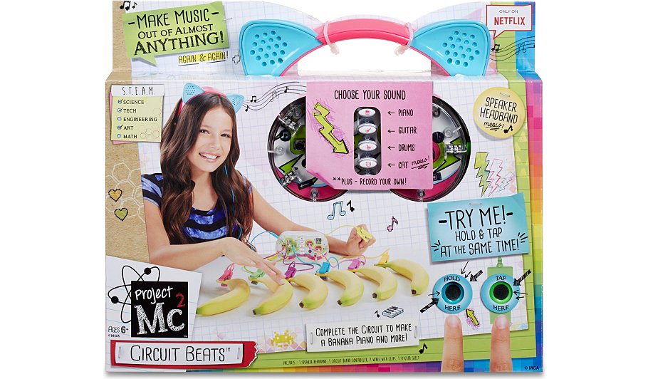
Introducing the Project MC² Circuit Beats
Check out the front of that packaging! It's our old friend the Banana Piano!
What is an MC²?
Project MC² is apparently a Netflix exclusive show aimed at getting young girls interested in STEAM. I watched a few minutes of the first episode and it's surprisingly well-produced, as long as you keep in mind that it was written for 'tweens. I'd say it's of similar caliber to your standard Disney Channel Saturday morning fare. It's a sort of live-action sitcom, featuring a cast of nerdy cool spy girls who use their various skills and science know-how to save the day. The show has a tendency to fudge the hacking here and there for the sake of the plot, but it does a good job of creating likeable "hacker" characters for young people to aspire to emulate.
In conjunction with the show, MGA Entertainment has also been releasing a line of dolls, toys and science kits. Each main character of the show has her own doll in a strategy reminiscent of the popular Bratz franchise (also owned by MGA). Interestingly, each doll also comes with a mini activity that emphasizes some aspect of STEAM. For instance, the Camryn doll comes with a tiny blueprint that leads you through the construction of her some-assembly-required skateboard (which she's often seen riding in the show). As pink-washed as these dolls and activities might be, they're a refreshing change of pace from the usual tiny dogs, hair brushes and glamorous accessories. The packaging also features a little more graph paper and duct tape than the usual aesthetic for toys focused at young girls. The toys and science kits are almost all adaptations of classic science experiment kits: a sort of "my first chemistry lab," a "grow your own rock candy" kit, a CO2 rocket, fizzy candy lab... all of these are the kinds of science kits you might find at an elementary school book fair. There are also toys that mimic props from the show, such as a high-tech journal and a "lie detector" (which is based on skin conductivity, but also has a hidden button for forcing false readings).
All in all, I think it's one of the more positive efforts by a toy company to support an interest in STEAM among young girls, and the science is actually pretty well researched. Even The Mary Sue gave the show an overall positive review. That said, most of the kits are derivatives of existing products with pink and purple style cues. The Circuit Beats is no exception.
First Impressions
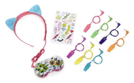
Image courtesy of MGA Entertainment
When I first unpacked the Circuit Beats and looked at the pieces together, it was pretty obviously a MaKey MaKey with some in-built sound-making stuff. Besides narrowing down the capabilities, they also made quite a few changes in the interest of kid-friendliness. Although the PCB is visible inside the toy (which I found kind of nice) the front of the board is brightly colored and labeled with little icons that imply the functionality of various buttons and jacks. The bare through-hole connectors from the MaKey MaKey have been replaced with TRS jacks for ease of connection. The alligator clips were toy-ified so as not to be too pinchy or sharp, and carry a matching TRS connector to plug in to the front of the toy. Instead of a built-in speaker or headphones, the Circuit Beats comes with a set of nifty cat-ear speakers on a sort of headband. Noticing that these were terminated with a stereo 1/8" jack, I immediately plugged them into my smartphone and started blasting the hardest Atlanta hip-hop in my catalog, hoping to exorcise the cuteness.
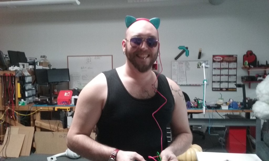
♪♫ ...'Bout to f#$& this cash up on a new toy, you can't understand us 'cause you're too soft... ♫♪ (photo courtesy of Jeff Branson)
After plugging in a few alligator clips and powering the toy on I was pleasantly surprised by how reliable the high-resistence switching was. It was every bit as responsive as the MaKey MaKey, and the selectable sounds were genuinely kind of fun to play with, although they sounded as though they were crudely pitched up and down by adjusting the play rate of the sample. The crown jewel feature of the toy is the ability to record your own sound onto the device (by pressing a button while talking into the microphone), and then play it back at various pitches in a sort of nod to the late '90s classic Yak Bak. The sound quality is similar to what I remember of the Yak Bak, and this was also genuinely entertaining for a few minutes, although it quickly devolved into a game of "what's the worst obscenity I can lay on this bad boy?"
Some effort seems to have been made to take the MaKey MaKey banana piano experience and divorce it from the computer. The sounds are all built-in, and the power is supplied by 3xAAA batteries. This limits the capabilities of the toy considerably, but it does make that particular mode of play much more portable and hassle-free. Unlike the MaKey MaKey, the Circuit Beats has only one ground clip, because it assumes that you'll just leave it clipped to yourself and then clip the other contactors to any produce within reach. After playing with the toy for a solid 20 minutes, I felt like I had pretty much fully experienced it and decided the time had come to take it apart.
Stripped Down
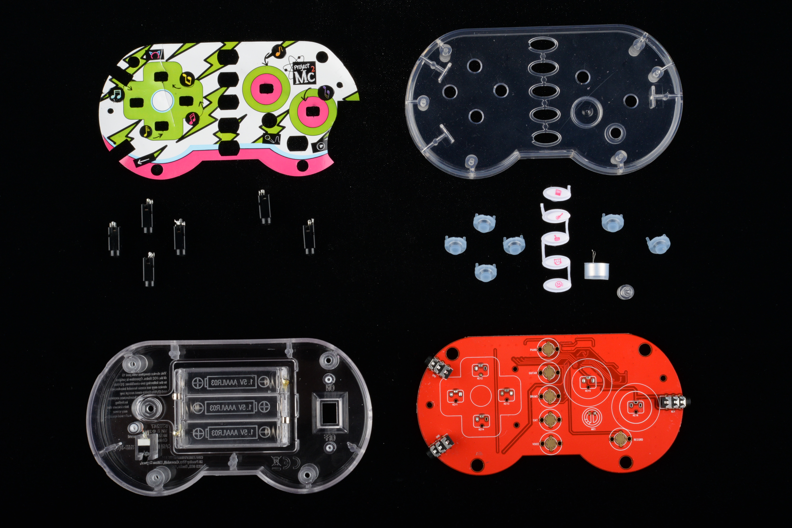
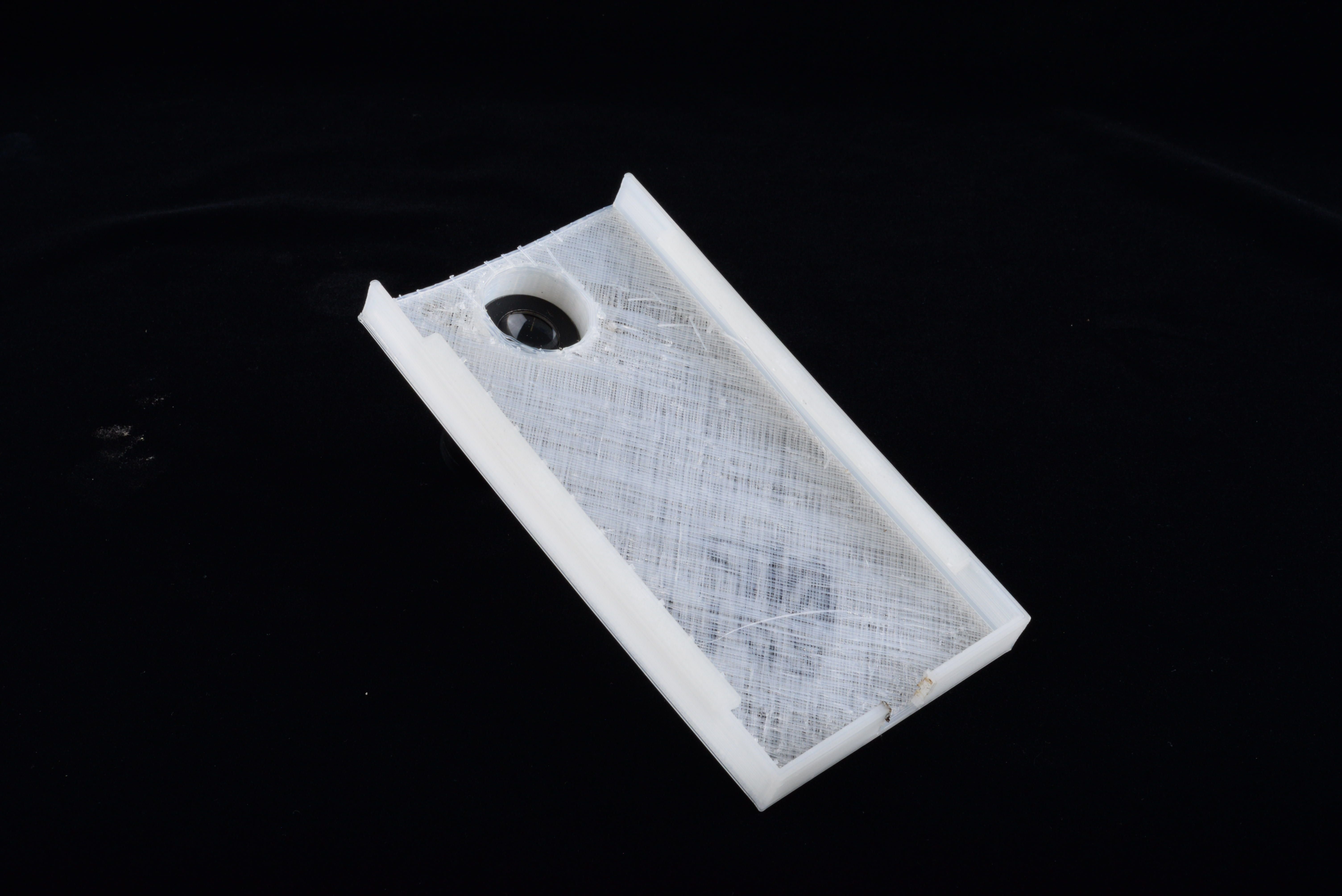
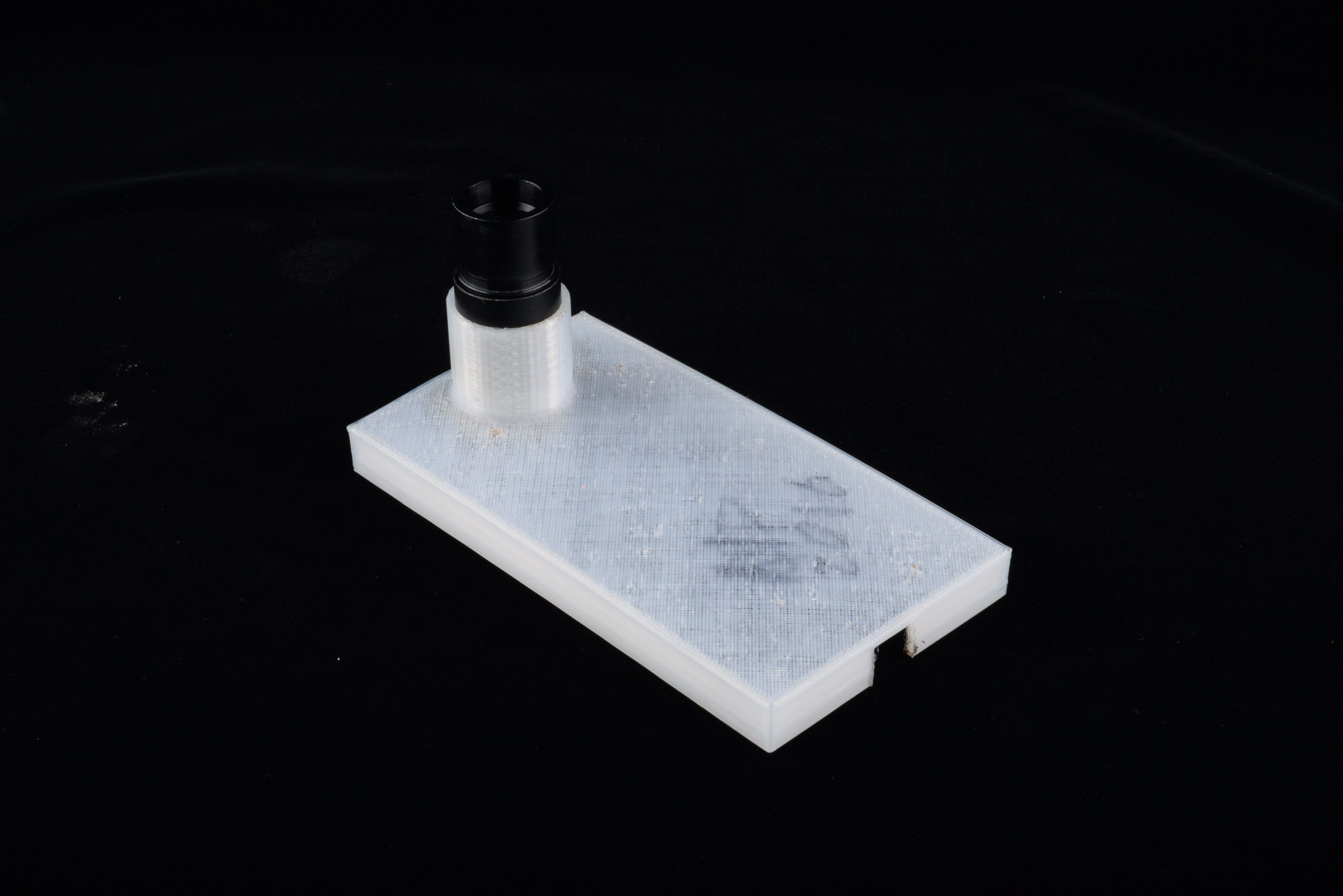
The toy came apart pretty easily after removing a few screws in the back. The construction was reminiscent of a classic gaming controller or a TV remote. Electrically, there's not much to this thing beyond the PCB itself. There's a battery holder, a power switch and a microswitch that appears to be there to put the toy into demo mode while it's on the shelf.
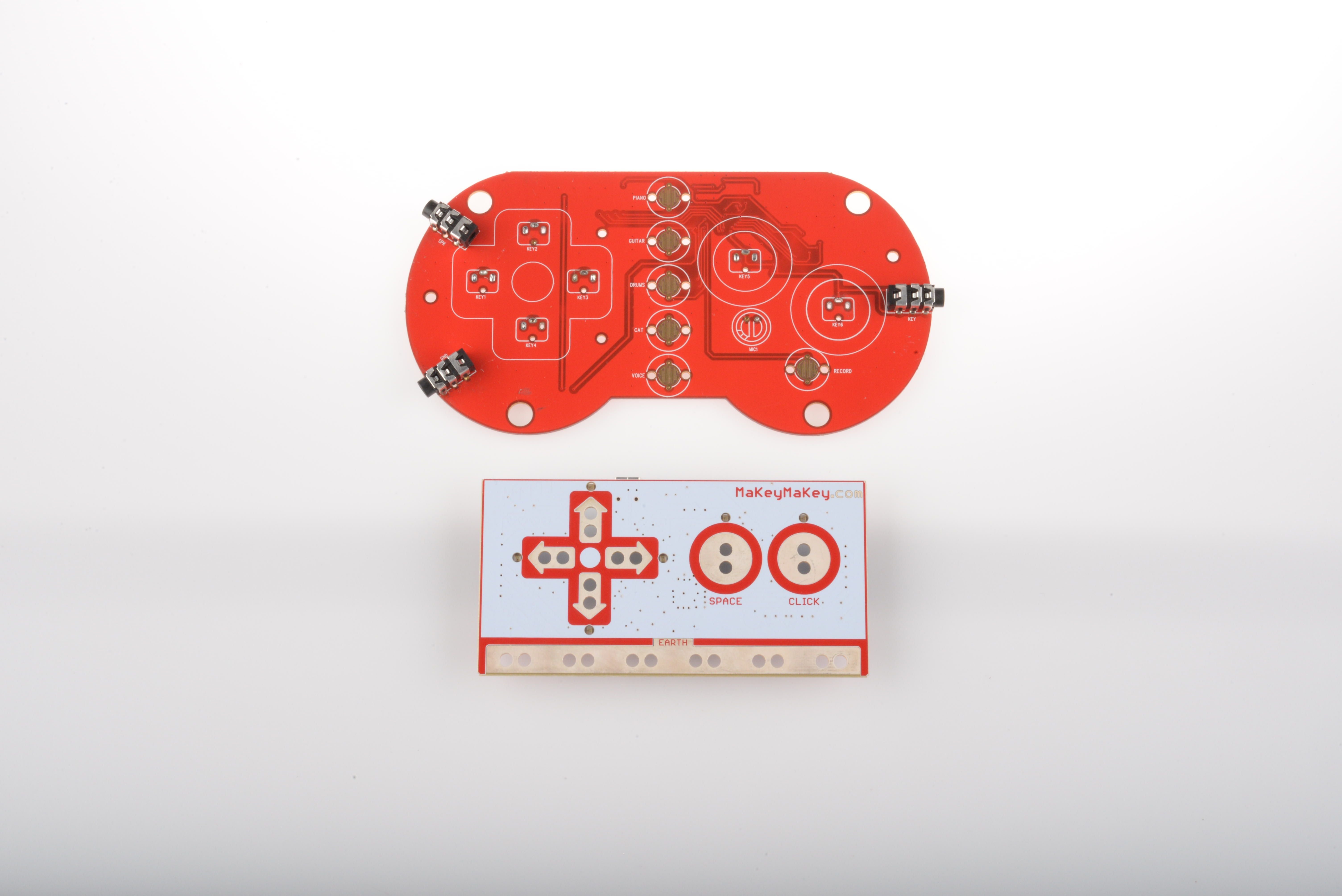
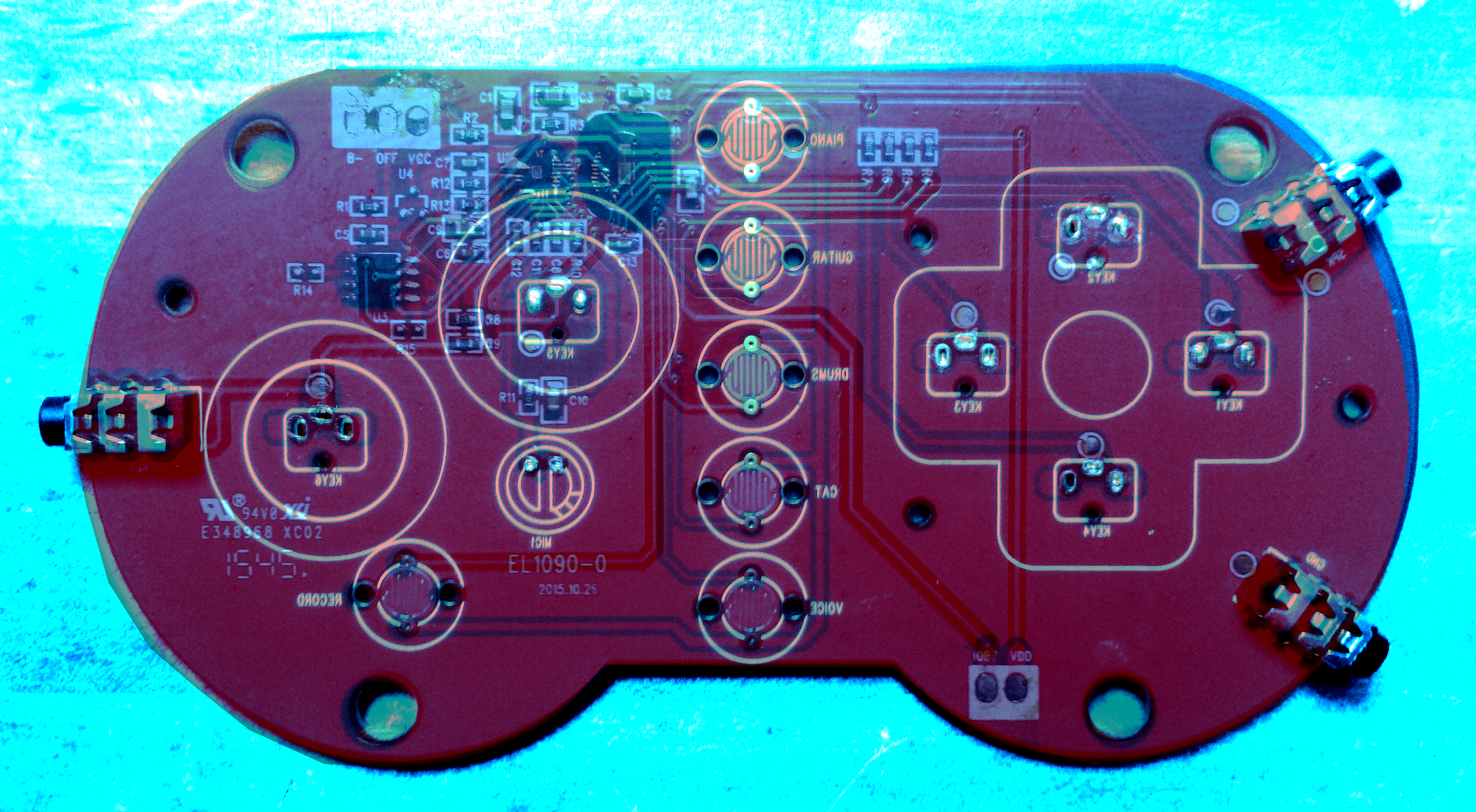
Circuit Beats PCB with the MaKey MaKey underneath for comparison
Instead of trying to do something too wild with the silkscreen of the PCB, MGA chose to cover the front of the exposed PCB with a nifty vinyl sticker. The die-cut on the sticker was a little rough and didn't line up exactly right, but was kind of a nice look. It looks like it was probably applied to the board before the PTH components were soldered in place. The only PTH packages on the board are the TRS jacks, six of which are vertically mounted in the front and three of which are horizontally mounted on the sides. All of them appear to be stereo jacks, but in the case of the clip connectors, the leads are all soldered together. Stereo connectors were probably used because their ubiquity makes them inexpensive.
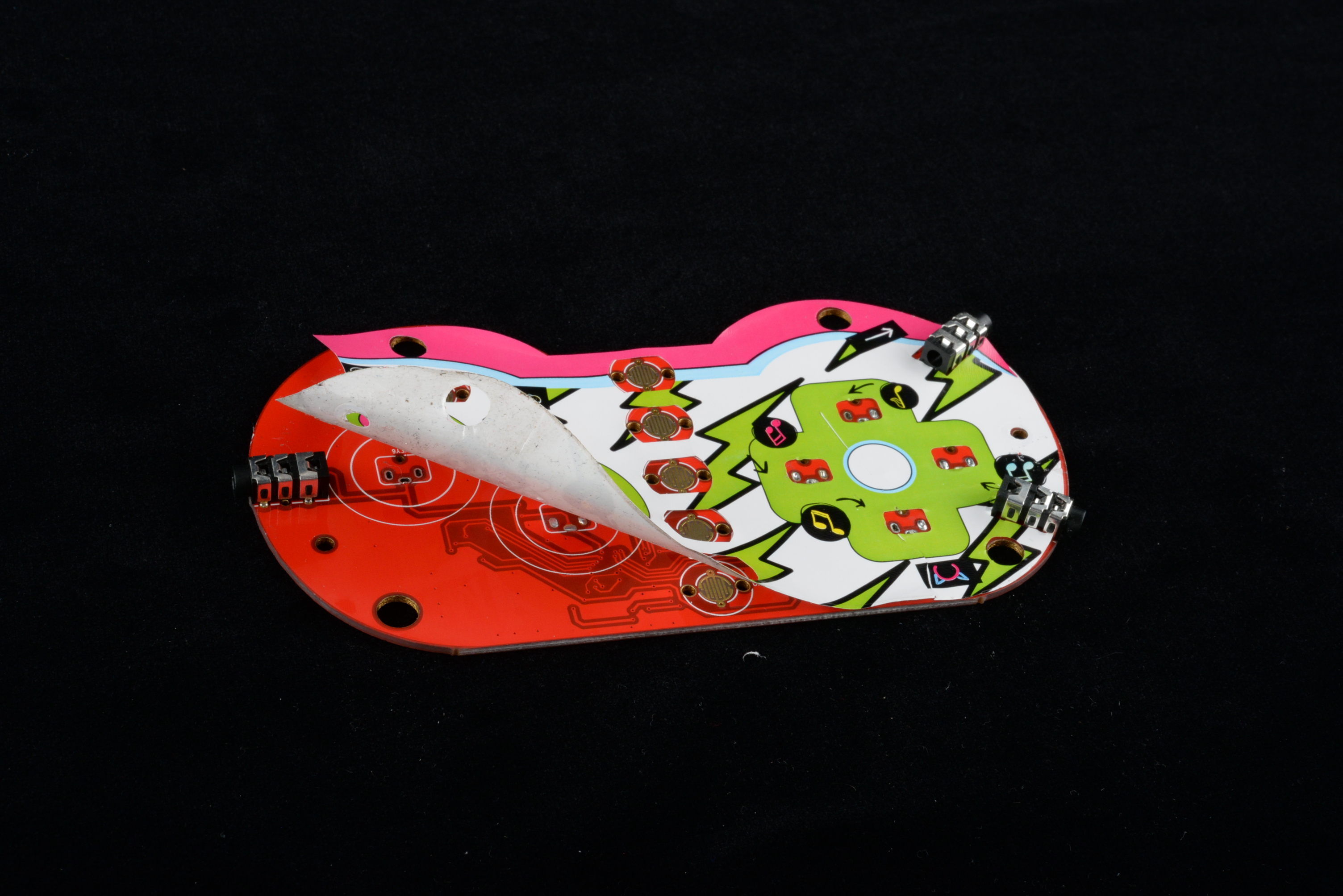
This sticker give the toy a more a-peeling look... I'll show myself out.
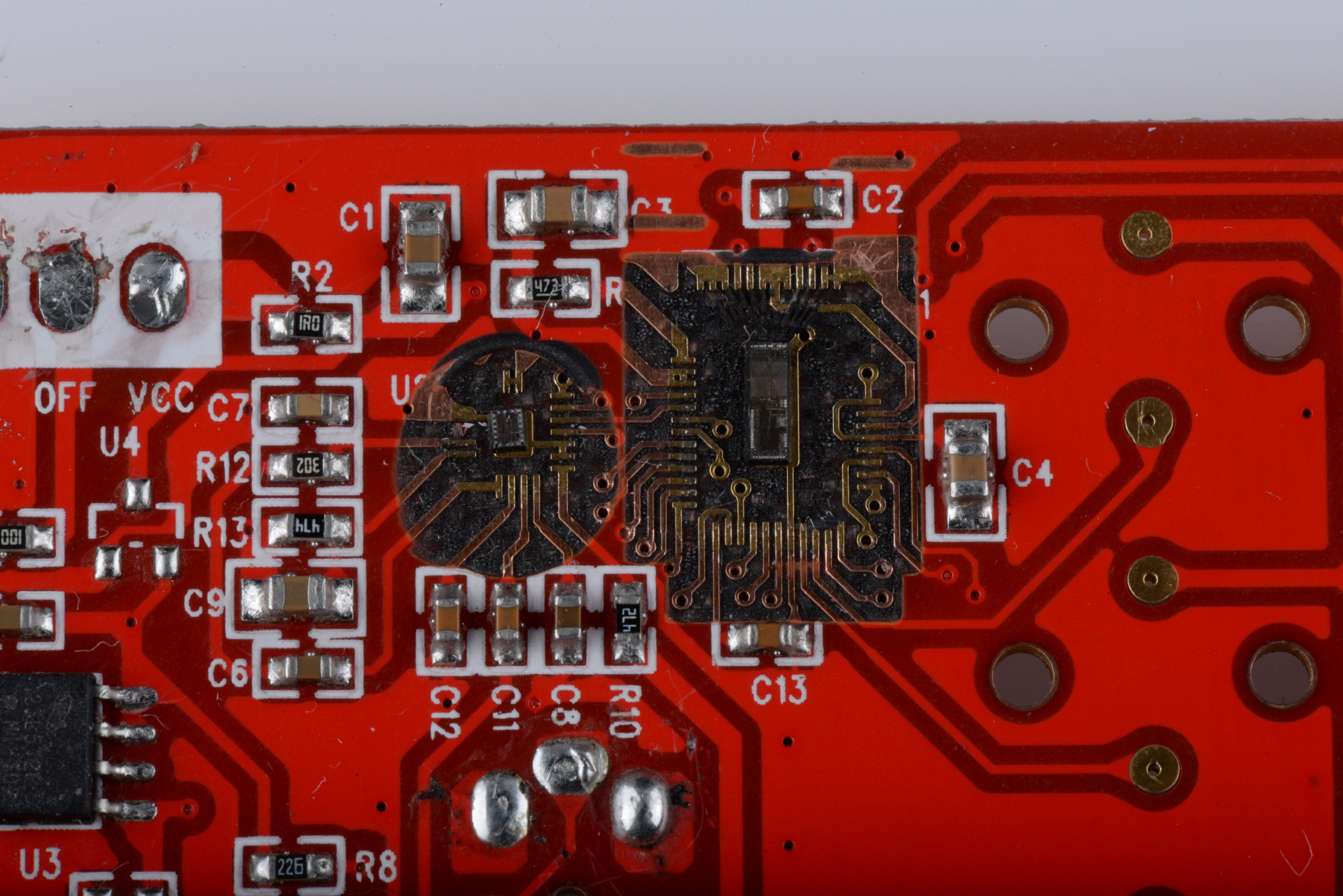
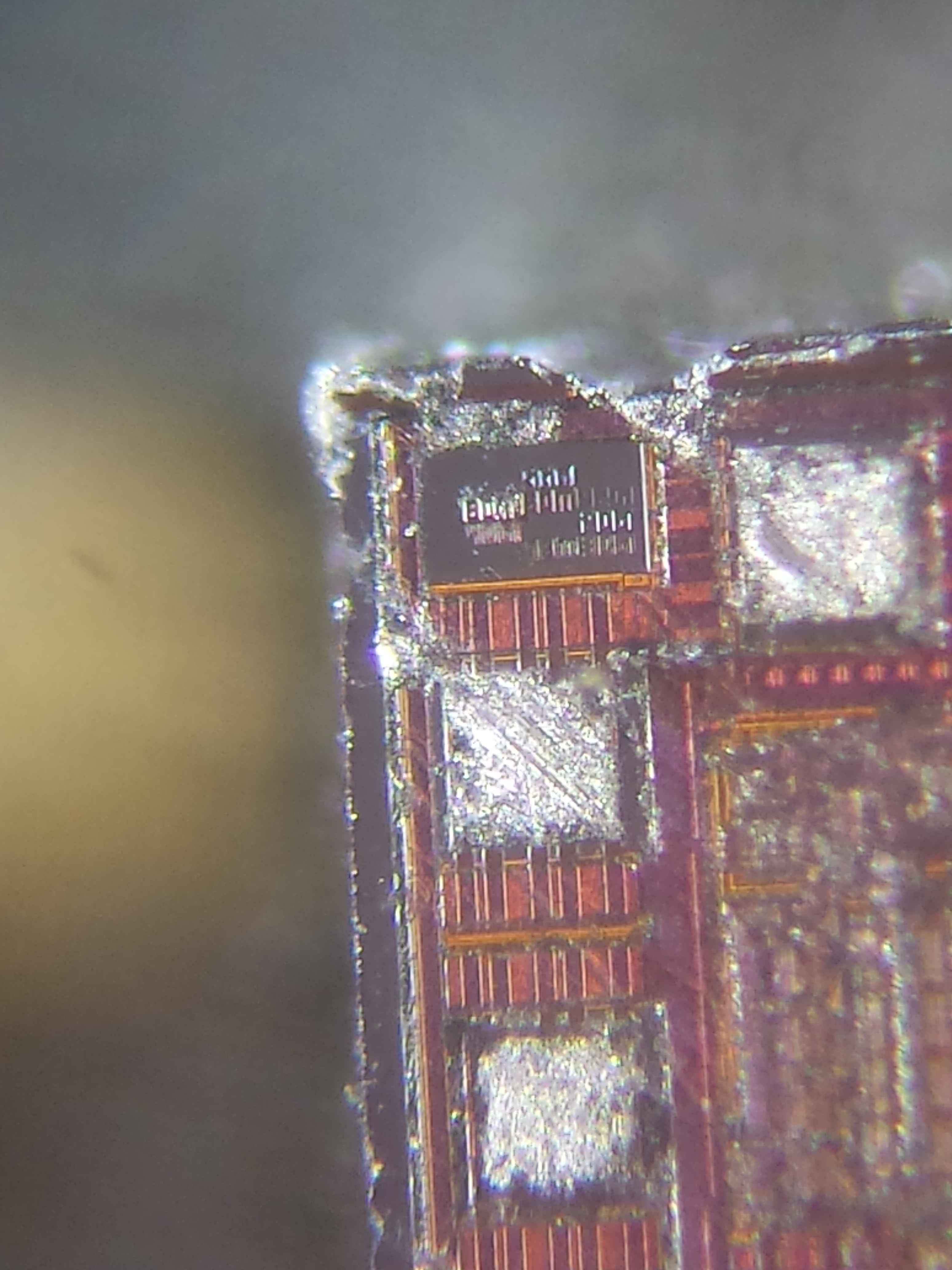
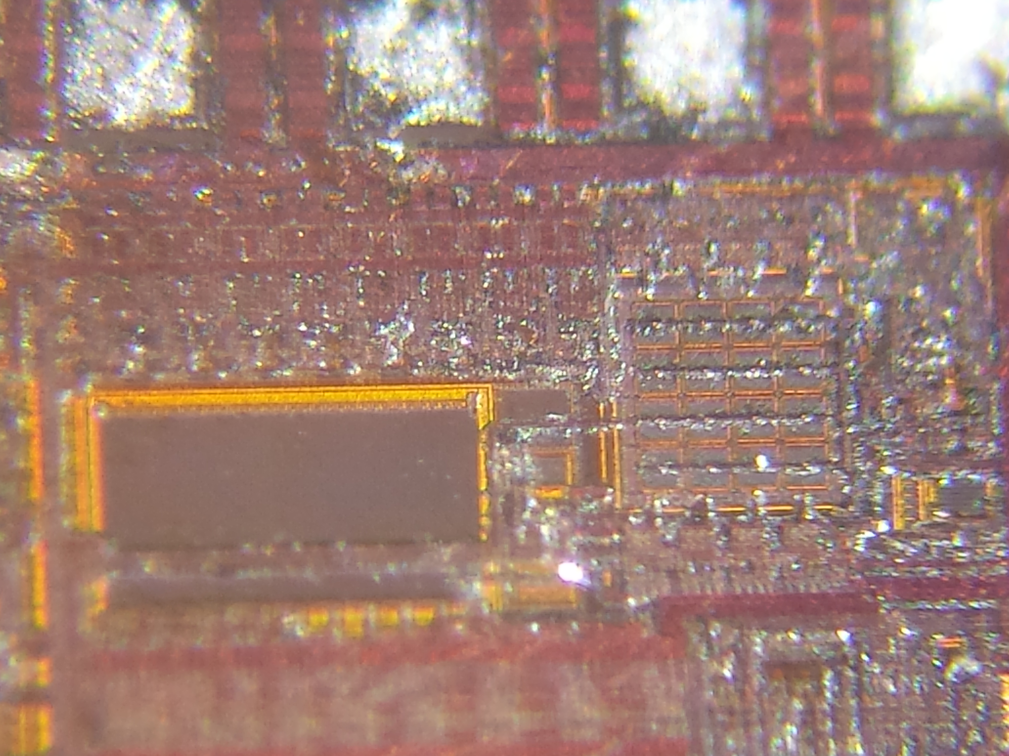
Flipping the board over reveals that the main components of the board are chip-on-board ICs. Chip-on-board components are bare silicon dies that are glued directly to the PCB and bonded to the surrounding pads by a wire-bonding machine. This eliminates the need for leadframe packaging, and is generally the cheapest way to get application specific ICs (ASICs) from a foundry. The bonded die is then covered in a protective "glop-top" epoxy layer. If you want to learn more about how chip-on-board components are placed, check out this great post about Nate's visit to one of our DMM manufacturers!
Fire Ze Lasers!
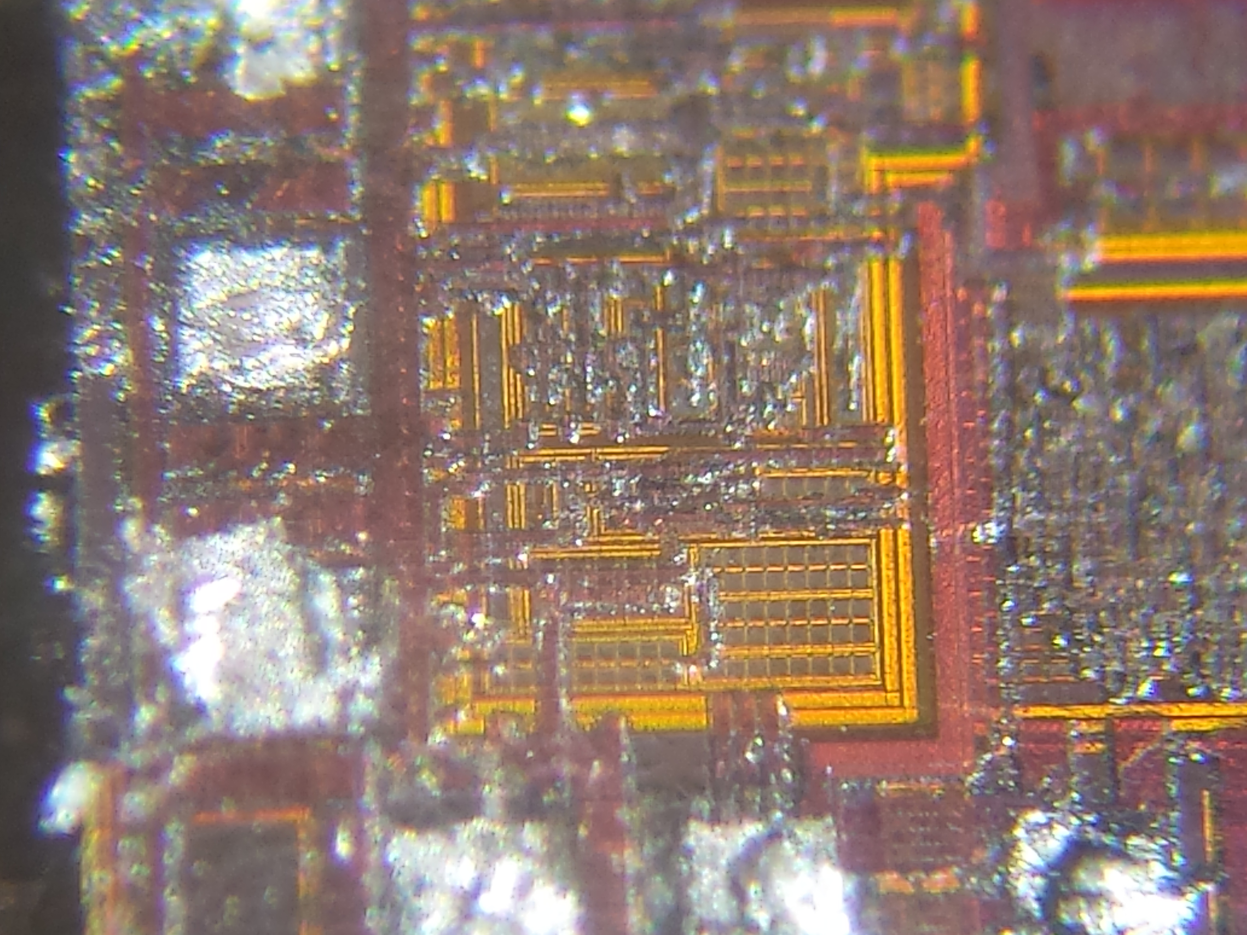
I really wanted to get under the glop-top and see what was running the show. Some silicon dies carry manufacturers' logos or serial numbers, after all, and if I could find one of those then we would know a whole lot about how they were functioning. Usually, exposing the die after it's been encased in epoxy (or "decapping," as it's usually called) is a chemical process. The most effective and popular solvent for this process is fuming Nitric Acid(!). I was willing to hunt someone down who had access to concentrated HNO3 if I had to, but then I remembered reading a blogpost from Jamie Craig about Laser Decapping ICs. Jamie had successfully removed the glop-top from COB parts using an inexpensive laser engraver. The laser did some damage to the bond wires and left a layer of gunk on the die, but since I didn't have any plans to analyze it during operation, that would be just fine.
I took the PCB to our Epilog laser engraver and started etching away the epoxy, layer by layer. The laser made short work of the epoxy and the underlying PCB without seeming to affect the silicon die at all. The whole process took only a few minutes. Here you can see the exposed dies. The only thing left to do was to get them under a microscope:
Time to get Tiny
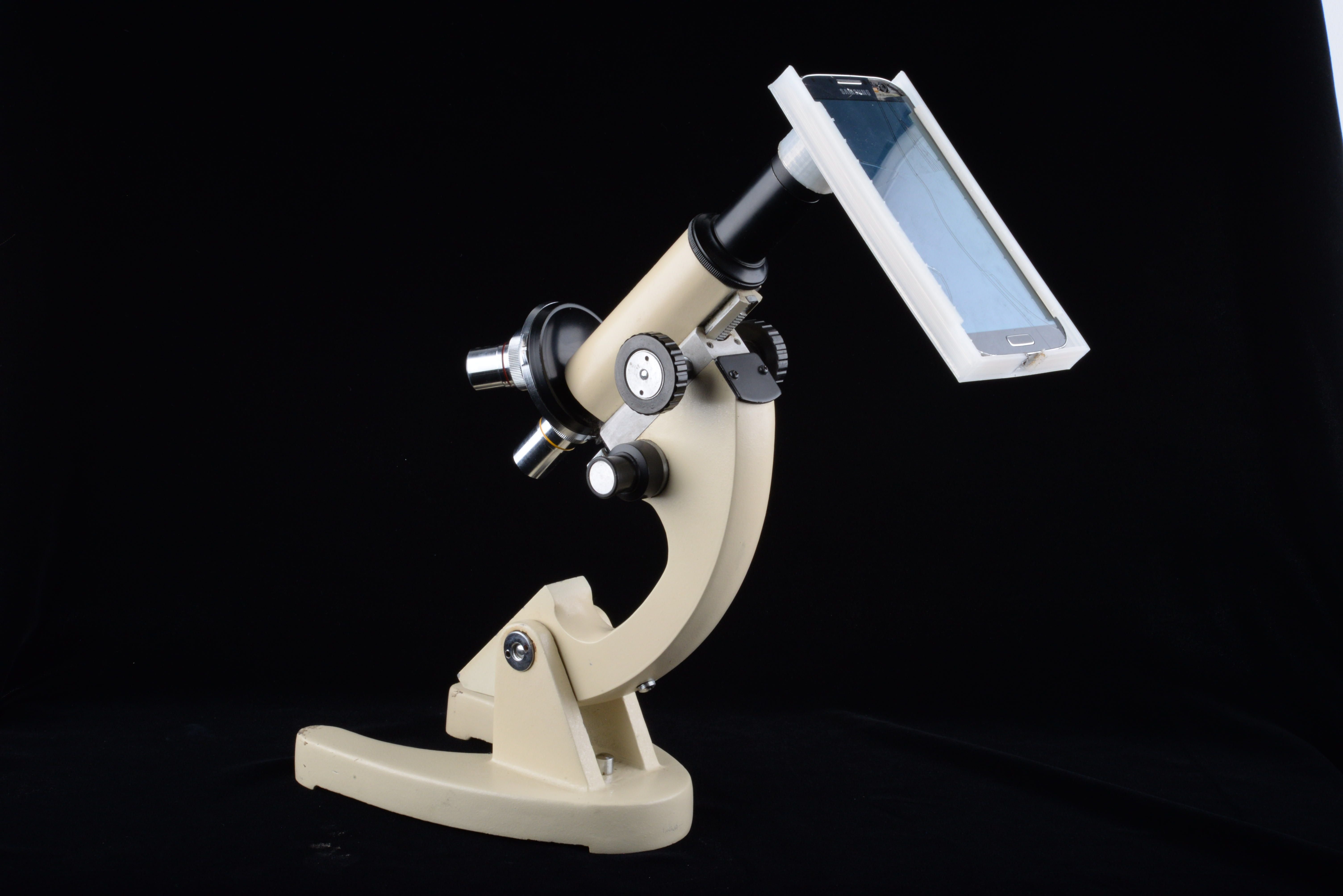
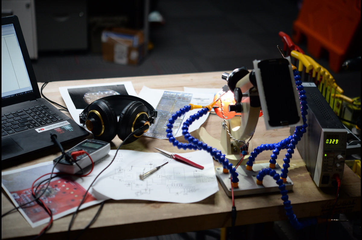
In order to hunt for microscopic writing, I was going to need a decent microscope. Luckily, I happen to own a fairly nice little Edmund Scientific microscope, which I've had since I was a young kid (thanks, grandma). In order to use my standard compound microscope to inspect the silicon dies, I was going to have to alter it. Most scopes of this type are designed to illuminate the subject from behind, but this wasn't going to work for our opaque PCB. There was also the problem of fitting the toy between the stage and the objective of the scope. The first step was to remove the microscope stage entirely. Then I set up one of our SparkFun Third Hand Kits behind the scope in order to hold the board in place. Two of the arms would hold the PCB in the correct orientation for inspection and another two would allow me to focus a pair of bright LEDs on the section of the board I was trying to inspect. I wired a pair of our 3W Warm White LEDs to a PicoBuck LED Driver and connected it to my benchtop power supply.
After using the scope this way for about an hour, I was getting a headache. Monocular scopes are a little hard on the eyes and I wanted to snap pictures of what I was seeing. I had tried holding my smartphone up to the eyepiece and was pleased with the quality of photo I could snap if I had the focal length just right. So I took a break from my microscopic haystack to build a tool. I used a set of calipers to make some measurements of my phone and sketched up a model for a microscope adapter. I loaded some 910 alloy on the Taz 5 and in about an hour, I was ready to rock. I heated up the end of the adapter with a small torch and forced it over the eyepiece in order to make a tight fit, and then cut a slot on the bottom of the adapter to facilitate my phone charging cable. Once I slid my phone into place, the camera lined up perfectly with the optics in the microscope and gave my scope a nice little LCD with digital zoom.
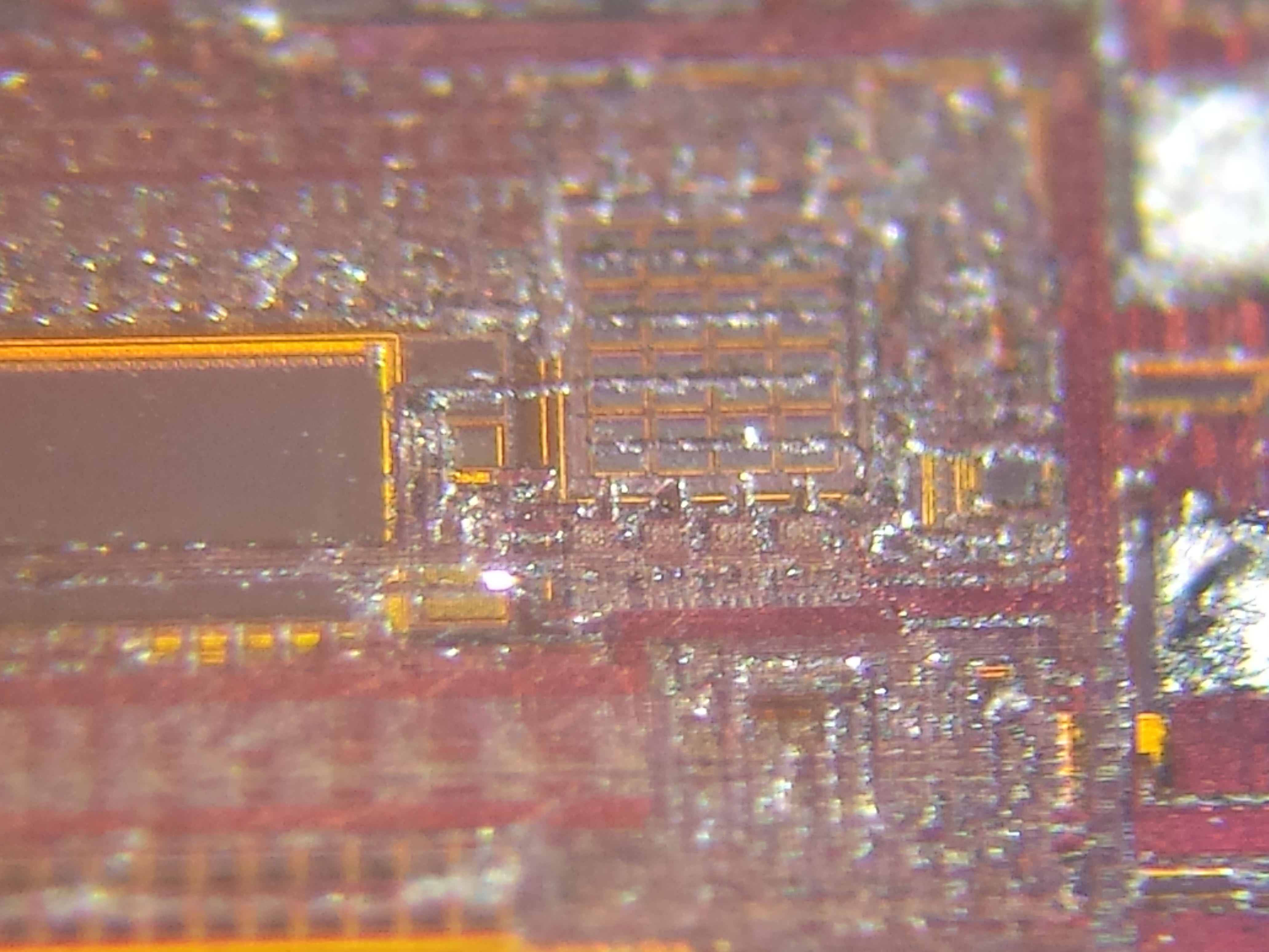
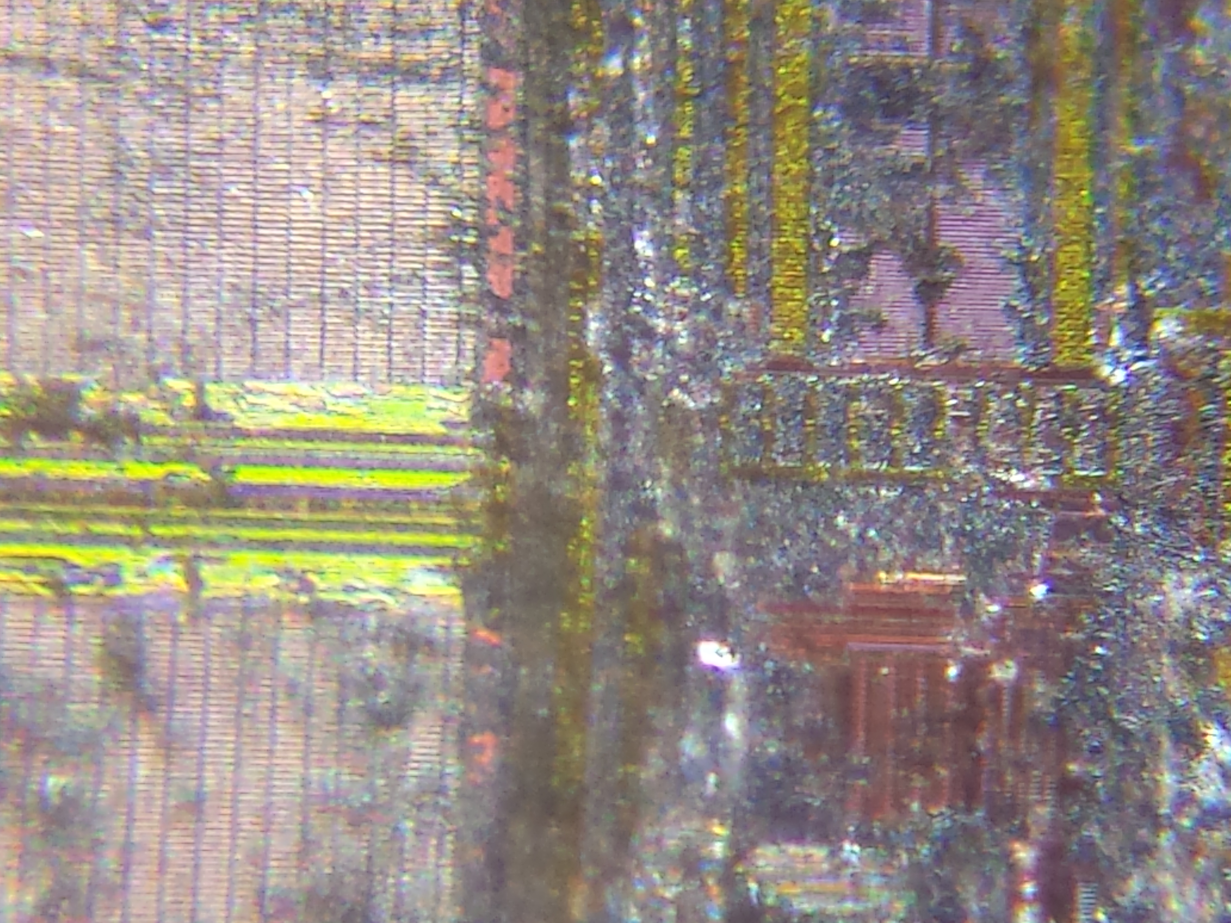
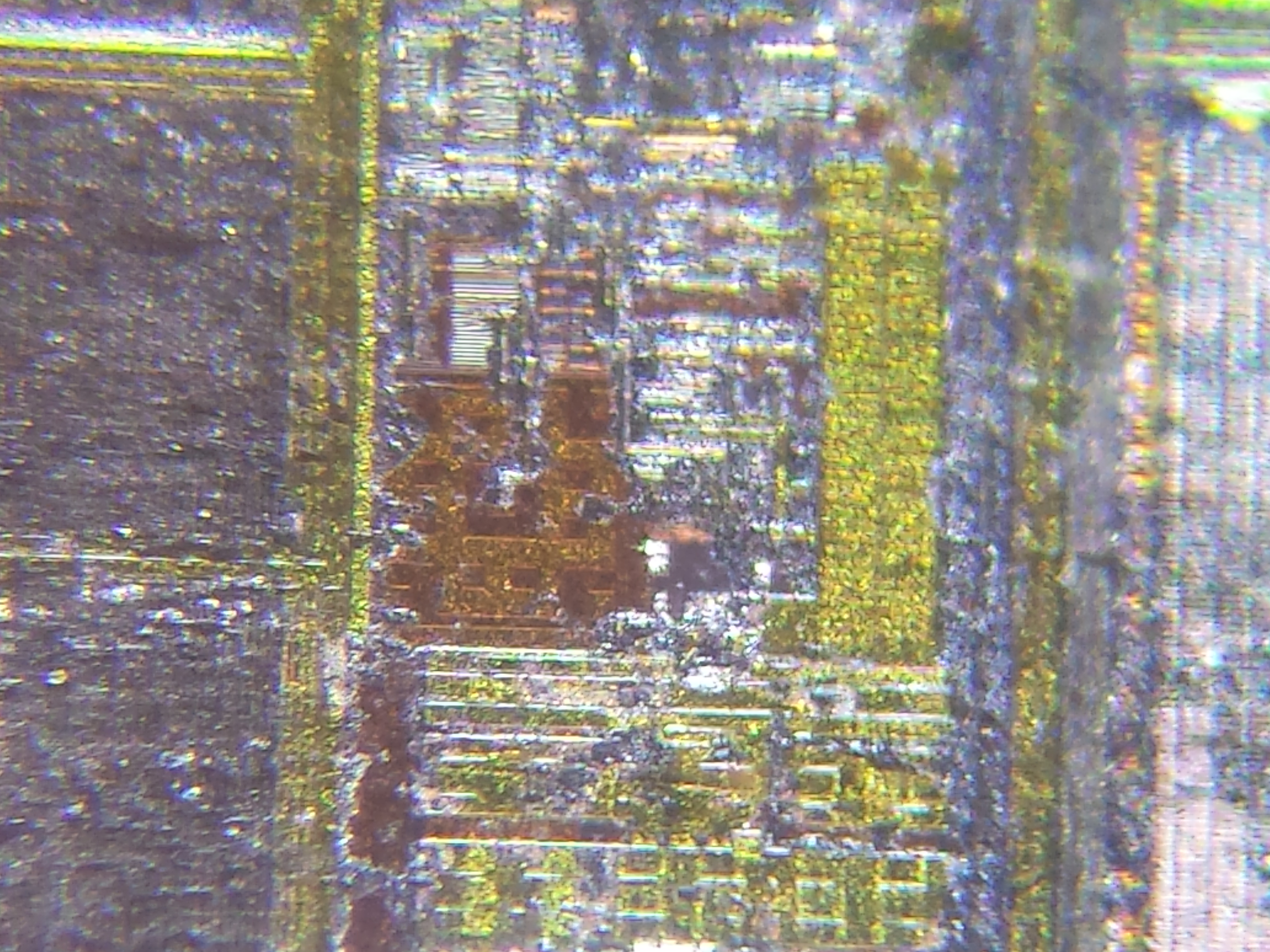
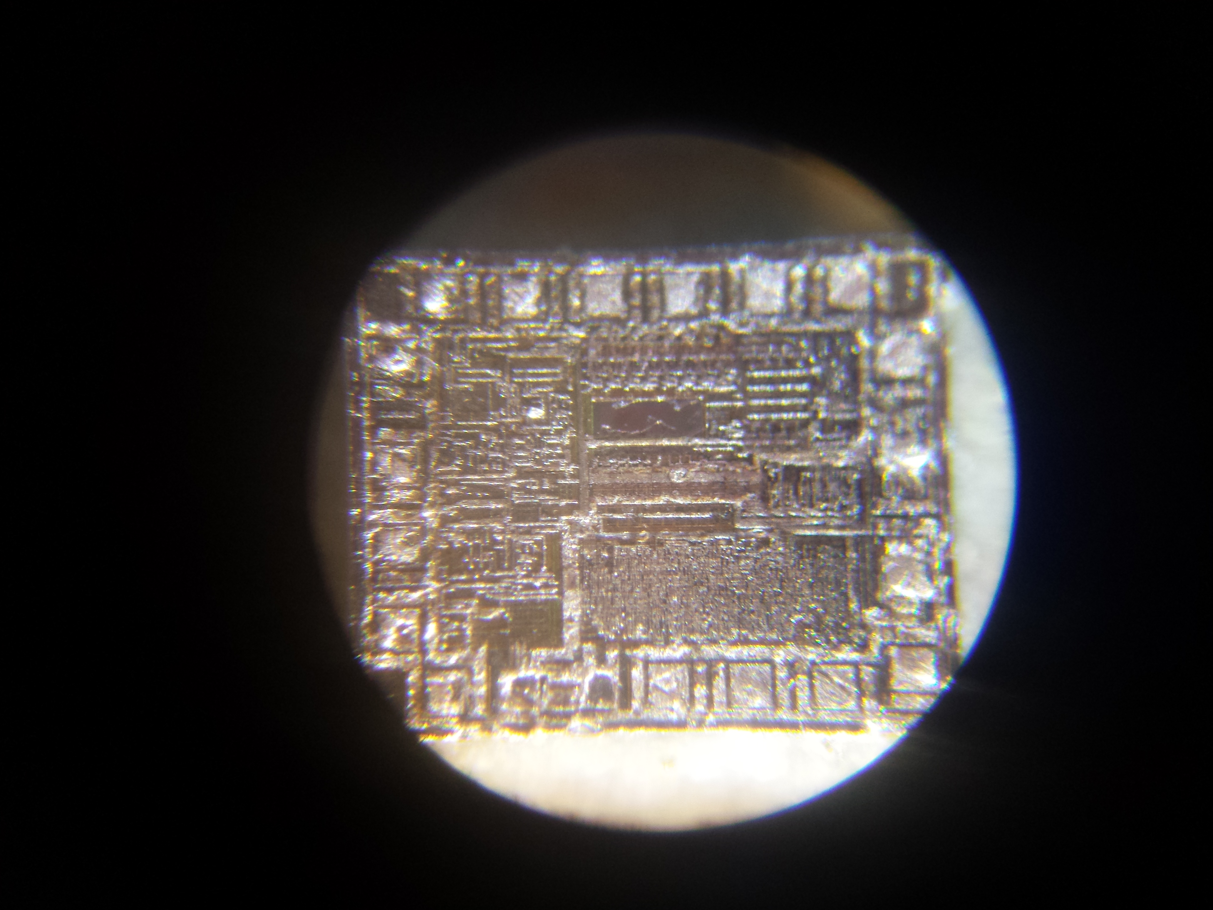
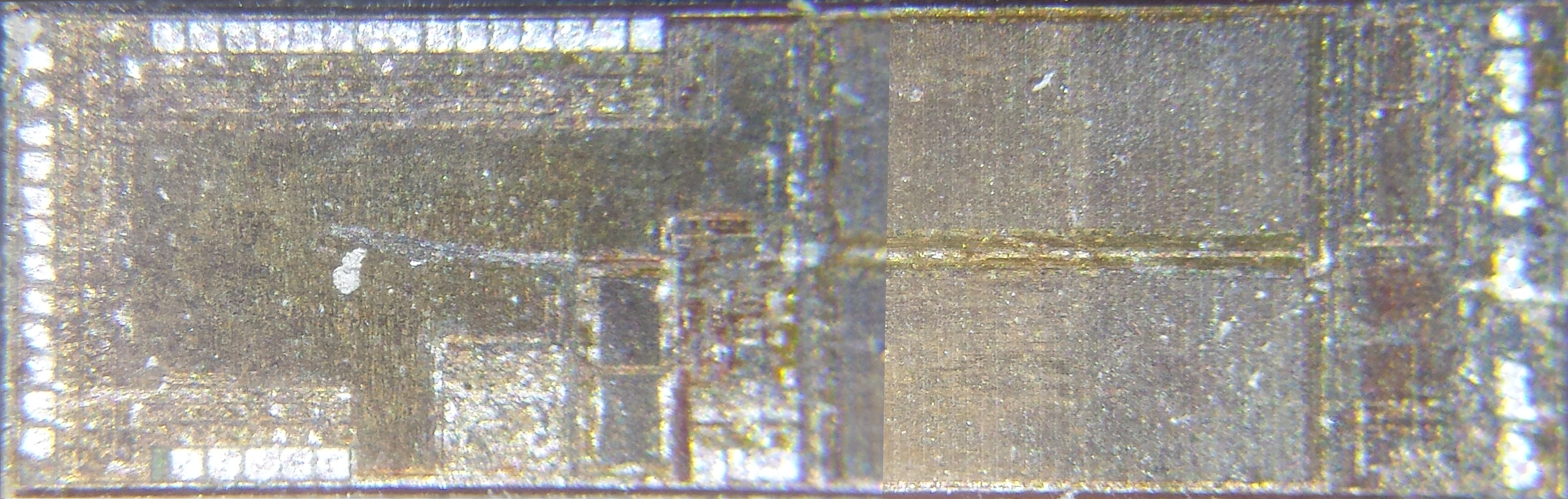
Unfortunately, I wasn't able to find any identifying markings on either die. I did, however, find what look like calibration marks. I also got some awesome views of the wafer level features. Here's a little gallery:

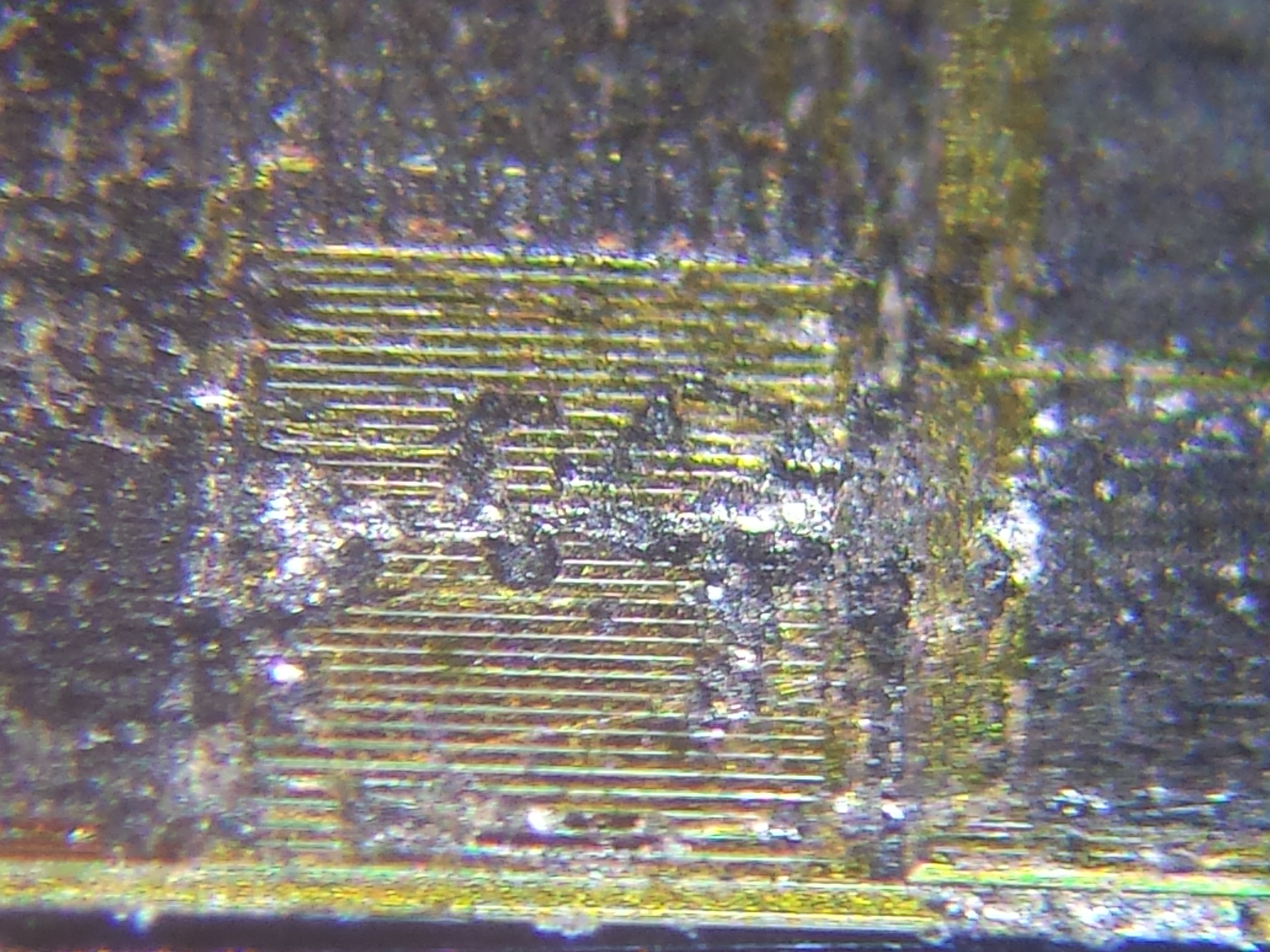
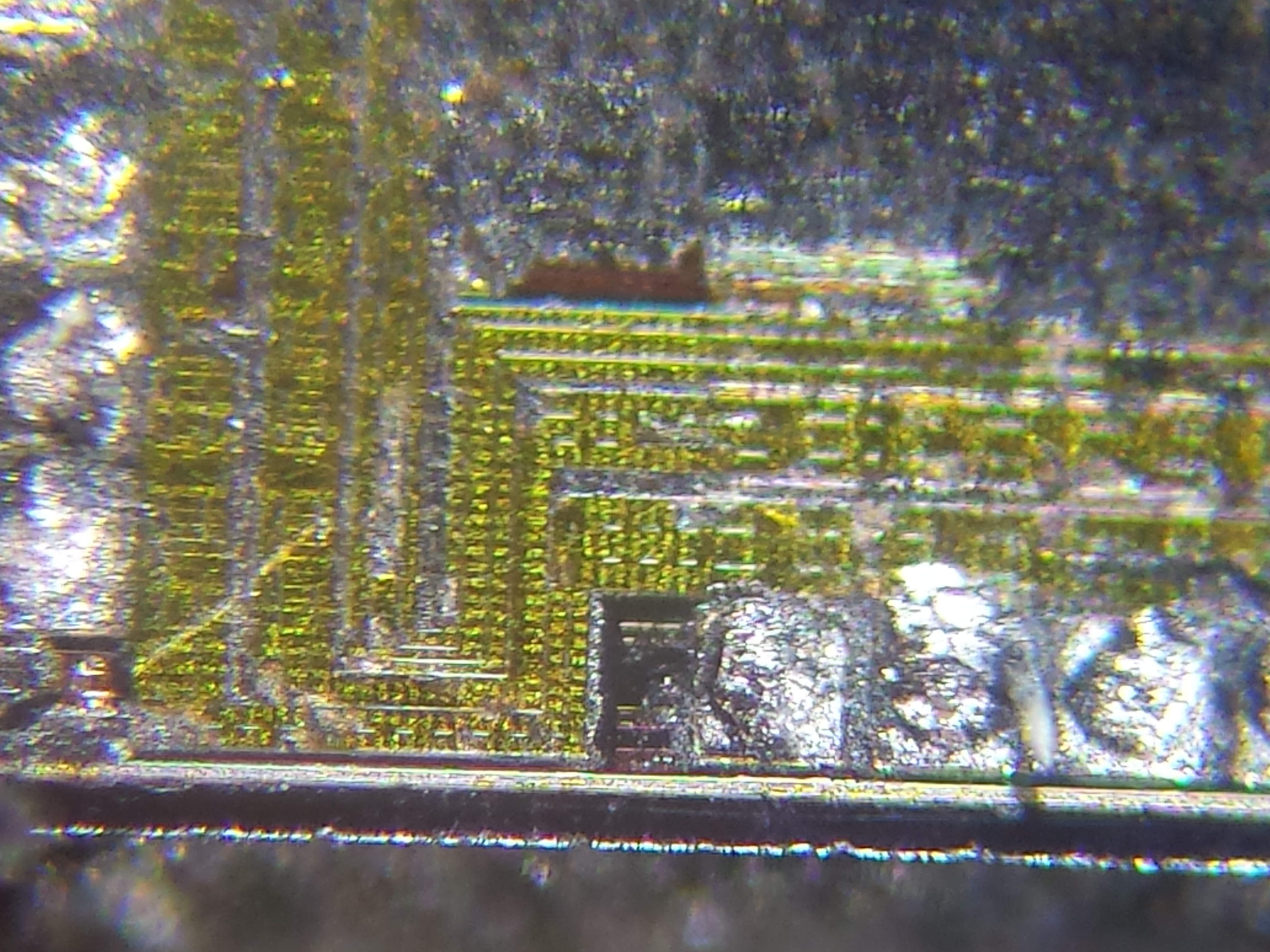
Click on any of the images to get a closer look!
So, given the lack of identifying markings, what can we learn? Well, let's look:
This is the smaller of the two ICs, and there isn't a lot to be learned from looking at it besides the fact that it's mostly logic with very little ROM. ROM and other types of memory appear as large linear arrays of features, like a cornfield viewed from an airplane. The lack of ROM means that this is probably not a microcontroller or something similar, because it doesn't have any space carved out for program memory. Also, the feature size is pretty small, which means that it's likely to be a logic component rather than a power component. It's connected to the other IC with a bunch of pins, so it's probably speaking some kind of serial protocol, and is not an amplifier or something. Let's look at the larger of the two:
Ah-hah! There's all the ROM we were looking for on the right side of the die (the little church pews). This little monster is definitely the brains of the operation. On the left side, we can see a squiggly mess; this is probably custom logic. There are a few little well-defined black squares toward the middle, which are likely working memory for the processor, which is probably in the light colored area to the left of them. I happen to know that the very right hand side of the chip is where the speakers connect, so there's an amplifier hidden in there to the right of the ROM somewhere...
To find out more about this toy, we're gonna have to figure out the schematic.
Reverse Engineered
My first course of action in trying to untangle the circuit was to take pictures of either side of the PCB and then superimpose them in Photoshop so I could see both sides at once and follow the traces through their vias.
This diagram was handy as I probed the board with my multimeter. I decided to draw the pads of the ICs on the board and begin labeling them with what they appeared to be connected to. I tested each pin one at a time for continuity in different sections of the circuit. Before long, I had most of the connections figured out and transferred it into EAGLE for easy viewing... feast your eyes:

Click on the schematic for a readable size
Luckily, there was one IC on the board that was labeled. It was a piece of FLASH memory, something like this. Knowing this was a big help in untangling how this circuit probably works.
It looks to me like almost everything is handled by the big microcontroller. It reads the inputs, amplifies, decodes and plays the sounds (probably loaded from the FLASH memory), and also does some power regulation for the FLASH chip and other IC. The other IC appears to be an ADC of some kind; it's connected to the microphone on one end and the controller on the other end. This is what translates the analog signals from the microphone into digital data to be stored in RAM. Judging by the way that the touch pads are laid out and the positioning of the resistors in the circuit, it would appear that they're doing the switching in exactly the same way as MaKey MaKey. Pretty cool stuff.
Derivative works and JoyLabz
So it looks like a MaKey MaKey, which is open source hardware, but there doesn't seem to be attribution anywhere on the product, website, packaging or user manual. Attribution and the release of the design files were literally MGA's only obligations under the CC BY-SA 4.0 license, and it appears that they failed to meet it. I'm not a lawyer, so I can't say whether or not this is strictly necessary. There may be an argument to be made that this uses sufficiently different technology in its implementation that it isn't legally a derivative work.
Is JoyLabz worried about it? Well, according to a 'funion who recently talked to JoyLabz's new Director of Education, not particularly.
This brings up an interesting question, though: If they were worried about it, would they even pursue it legally? Because they were never entitled to money from derivative works, as per the license, JoyLabz couldn't seek monetary damages. They could, at best, seek to force attribution on future products and the release of the designs under the same license. But litigation is expensive, and the attribution may not be worth it... so what stops a company like MGA from using these designs without attribution, knowing that smaller companies and makers won't waste money pursuing them? Well, again, I'm not a lawyer, so I don't know.
I don't mean to paint MGA in a terrible light. This is a cool toy, and it seems like part of a cool brand. Unfortunately, it also seems to me like this should have been released under a CC BY-SA 4.0 (Share Alike!). Maybe some of you OSHW folks know better than I do and can set the record straight: Is this an Open Source victory? Or is it a blatant copycat?


Yes, this product should absolutely be open hardware as it's an undeniable derivative of the Makey Makey and have documentation released under CC BY-SA 4.0
Hey, there's an authority on the subject! Thanks for weighing in! :)
Hmm, I wasn't so sure whether this would be a license violation. My informal understanding was that copyright only applies to design files (and one or two other things, like "mask works"). In this case a PCB layout isn't even being copied, only possibly part of a circuit schematic, so copyright wouldn't apply. The relevant IP legal framework would be patent protection, either on the high resistance touch technology (did Makey Makey pioneer this?) or it's application to user interaction or musical experimentation (AFAIK Makey Makey did popularize this use case, though there might have been prior art).
I think it's very likely that this product is conceptually and in spirit a derivative work of the Makey Makey, and for educational and all kinds of other reasons it should be open hardware.
I would be curious to hear from the Makey Makey folks; is it possible they were consulted or even collaborated on this product?
EDIT TO ADD: noting that Alicia never claimed this was a license violation, just that it "should" be open hardware.
Regarding the high resistance touch technology, the early version of the Makey Makey circuit was the same as an example Application Note published by Atmel.
I doubt they want to release it with a share-alike license, as then they'd have to release circuit diagrams, source code, sound files, etc. and they may well have used some licensed content there. Some attribution would have been nice, however.
Adding lasers generally makes things better, but removing the glob top! Sweet teardown
This tear down definitely tore down further than I expected. :D That was awesome to see.
Nice teardown. Would also be good to see an article about MakeyMakey switching from the 32u4 to the PIC?
I see JoyLabz has MakeyMakey in the scholastic catalog this month. I suspect they're too busy shipping to have time to consider fakes. Congrats on their high volume marketing.
JoyLabs changed to a PIC but we are still using the 32U4 on our board so we can't speak to the reasons behind their decisions.
Seems to me MGA has an engineer or two that thought they got away with something. I have never heard of their program, and don't think I will encourage my girls to check it out; we will hack on our own and don't expect to mimic copies. I did however enjoy the tear-down and insight into cheap toy design.